

ProductPRODUCT
Featured products



Contact Us
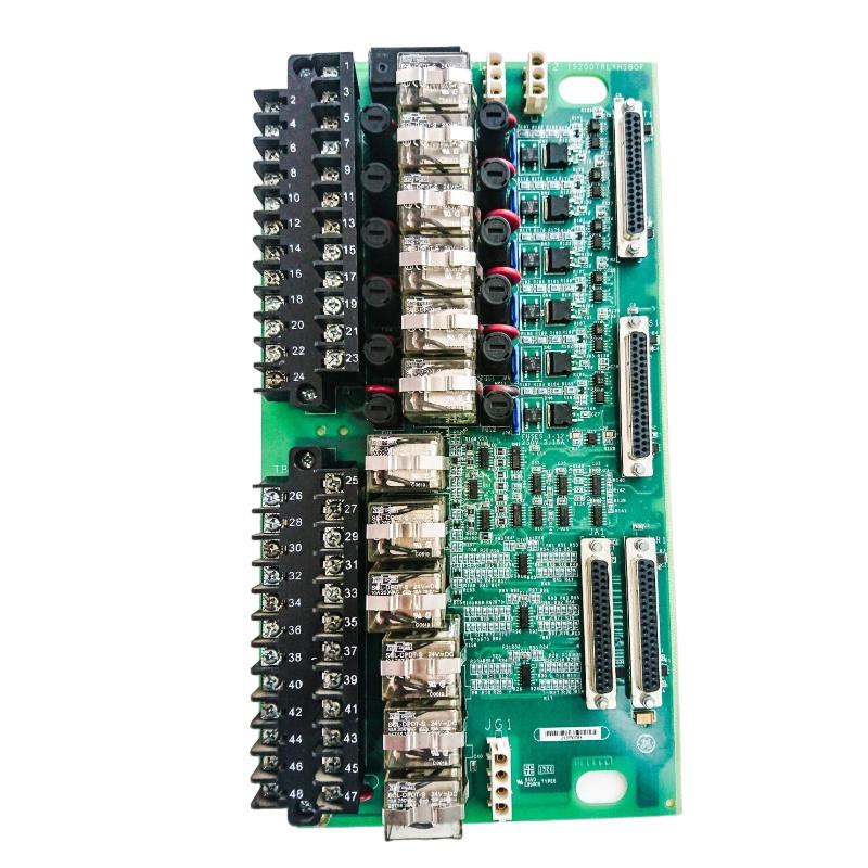
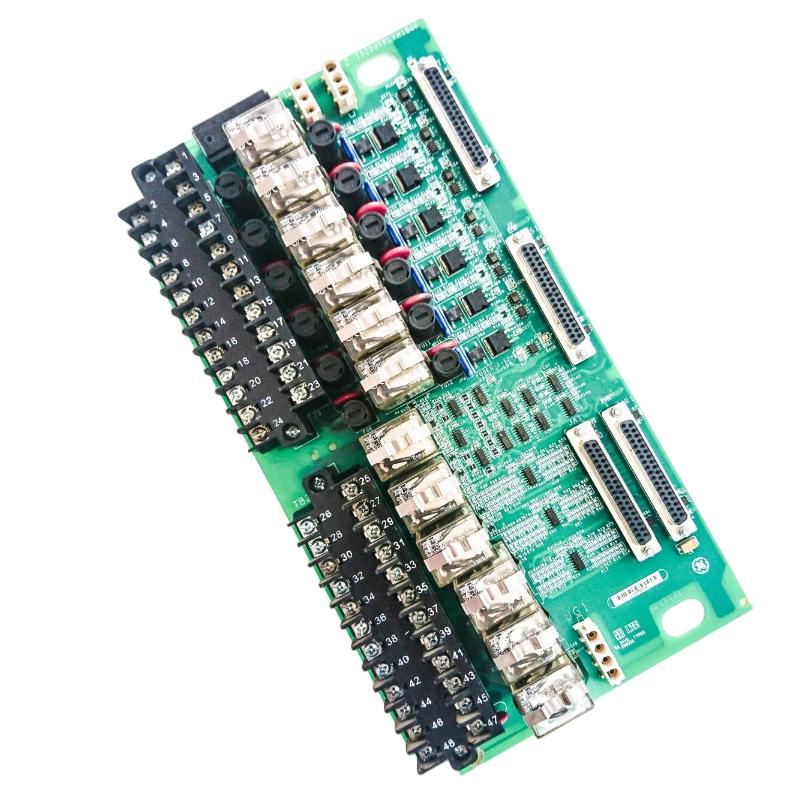
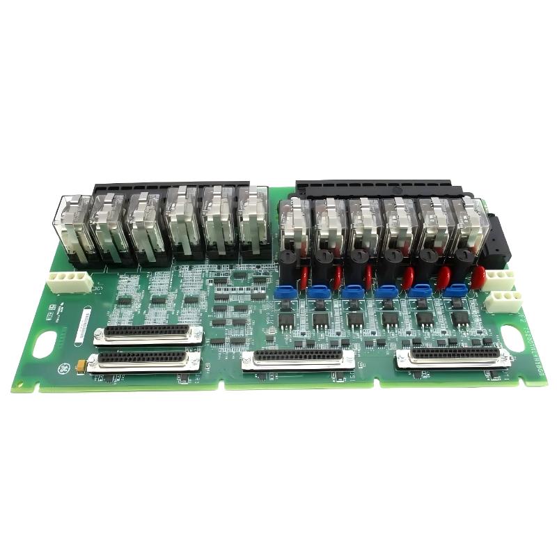
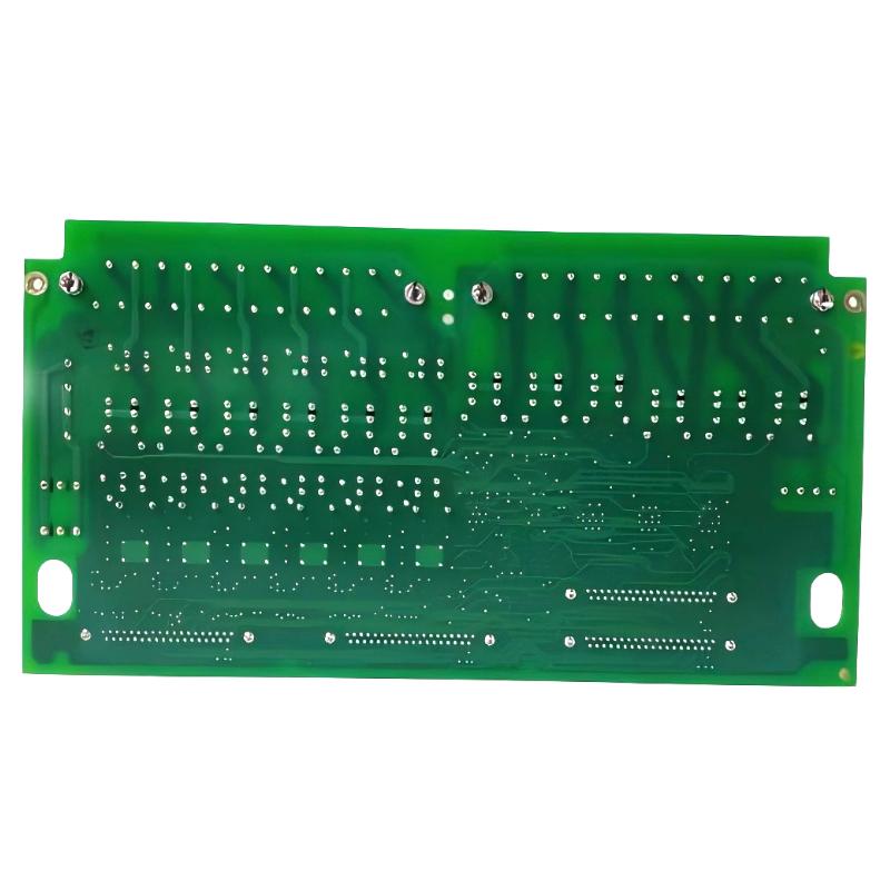
- GE
- IS200TRLYH1BGF
- Relay Output Terminal Block
- USA
- 330.2 x 20 x 178 mm
- 0.6 kg
- Xiamen, China
- New & In Stock
- T/T, PayPal, Western Union
- 1 Year
- 1-3 Working Days
- DHL, UPS, TNT, FedEx and EMS.
- 24-Hour Service
- COO
- 37
Our advantage

Global Logistics
We have a 10-year logistics and express cooperation agreement, so our products can be shipped to any place in the world.

Brand new and original
Our products are imported in bulk from the place of origin. Because of the cooperative relationship, our products are all original and 100% new.

24-hour service
We provide 7*24 hours service to our customers. We will be there whenever you need us.

Price advantage
All our products are priced very favorably because we have our own warehouse and supply.
| Company Information | |||
| [email protected] | |||
| Mobile | +8615980777398 | ||
| +8615980777398 | |||
| 15980777398 |
Product Overview
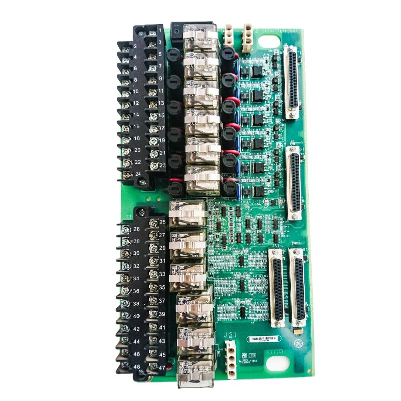
The GE IS200TRLYH1BGF Relay Output Terminal Block is an industrial control interface component designed to organize relay-based output connections between compatible GE control-system electronics and external field equipment. As part of the GE IS200 family, the IS200TRLYH1BGF provides a structured termination point for output circuits used in industrial automation, equipment control, alarm systems, and interlock applications.
Relay output interfaces are commonly used when a control system needs to switch an external circuit according to programmed operating conditions. Depending on the host-system configuration, relay outputs can be associated with contactors, auxiliary relays, solenoids, annunciators, alarms, actuator circuits, and other discrete field devices.
The GE IS200TRLYH1BGF has listed dimensions of 330.2 × 20 × 178 mm and a weight of approximately 0.6 kg. Its long, narrow physical profile is suitable for control-panel installations where organized field wiring and accessible terminal connections are important considerations.
The IS200TRLYH1BGF should be installed only in a compatible GE control architecture. Exact terminal assignments, relay characteristics, electrical ratings, connector arrangements, and system compatibility should be verified against the applicable equipment documentation and hardware revision before installation.
Technical Specifications
| Parameter | Specification |
|---|---|
| Manufacturer | General Electric (GE) |
| Model | IS200TRLYH1BGF |
| Product Family | GE IS200 Series |
| Product Type | Relay Output Terminal Block |
| Primary Function | Relay output termination and field interface |
| Signal Type | Discrete / Relay Output |
| Interface Role | Control-System-to-Field Device Interface |
| Application | Industrial Control and Automation |
| Installation | Compatible GE Industrial Control Equipment |
| Dimensions | 330.2 × 20 × 178 mm |
| Weight | 0.6 kg |
| Mounting | System-dependent |
| Typical Applications | Relay outputs, alarms, interlocks, actuator control, auxiliary equipment |
What Is the GE IS200TRLYH1BGF?
The IS200TRLYH1BGF is a GE Relay Output Terminal Block intended to provide an organized physical interface for relay output circuits within a compatible industrial control system.
The terminal block should not be confused with a PLC processor or controller. Its primary purpose is associated with field wiring and signal termination. The control logic is executed elsewhere in the control architecture.
A simplified signal path is:
Control Processor → I/O / Relay Interface → IS200TRLYH1BGF → Field Wiring → External Equipment
The control processor determines when an output command should be generated. Associated relay circuitry changes the state of the output circuit, while the terminal block provides the physical connection to the external field wiring.
This arrangement helps separate control electronics from field wiring and provides a more structured method of connecting industrial equipment.
Relay Output Terminal Interface Fundamentals
Relay output circuits provide a practical way for industrial control systems to switch external electrical circuits.
Typical discrete states may include:
- ON / OFF
- Start / Stop
- Enable / Disable
- Open / Close
- Active / Inactive
- Alarm / Normal
- Permissive / Not Permissive
A typical control sequence can be represented as:
Control Logic → Output Command → Relay State → Terminal Interface → Field Device
The exact electrical behavior depends on the associated output hardware and system configuration.
The terminal block itself provides the connection structure needed to route the relevant relay output circuits toward external equipment.
Function and Working Principle
Control-System Command
The control processor evaluates the application program together with process conditions, permissives, and interlocks.
When the required conditions are satisfied, the controller generates an output command.
Relay Activation
The associated relay output circuitry responds to the command and changes the state of the relevant relay circuit.
This switching action allows the control system to operate an external circuit.
Field Connection
The switched circuit is routed through the IS200TRLYH1BGF terminal interface and into the appropriate field wiring.
The connected equipment then responds according to its own electrical design.
Equipment Operation
Depending on the application, the relay output may be used to control:
- A contactor
- A solenoid
- An auxiliary relay
- An alarm
- An actuator
- An external control circuit
Output Deactivation
When the control command is removed, the associated relay circuit returns to its configured state.
The exact behavior depends on the design of the host output system.
Role in Industrial Automation
The IS200TRLYH1BGF can form part of the field-interface layer within a larger GE industrial automation architecture.
A typical system can be represented as:
HMI / SCADA → Control Processor → I/O → Relay Output → Terminal Interface → Field Equipment
The operator interface provides commands or displays equipment information.
The control processor executes application logic.
The output system produces the appropriate control signal.
The relay interface provides the required switching function.
The terminal block organizes the field connections.
Finally, the external equipment performs the commanded action.
This layered structure helps industrial facilities manage complex equipment while maintaining organized cabinet wiring.
Industrial Applications
Turbine and Generator Control
Industrial turbine and generator systems can contain numerous discrete output circuits.
Relay outputs may be associated with:
- Auxiliary pumps
- Cooling equipment
- Valve controls
- Alarm systems
- Equipment permissives
- Breaker interfaces
- Auxiliary control circuits
A terminal interface helps organize these field connections.
Motor Control
Motor-control applications frequently use relay outputs to operate external contactors and auxiliary circuits.
Possible functions include:
- Motor start
- Motor stop
- Motor enable
- Contactor activation
- Equipment reset
- Auxiliary control
The terminal interface provides the physical connection between the output circuit and field wiring.
Valve and Actuator Applications
Industrial valves and actuators can use discrete commands for:
- Open
- Close
- Enable
- Disable
- Reset
Relay-based outputs can provide the switching interface required by the equipment.
Alarm and Annunciation Systems
Relay outputs can be used to activate:
- Warning lamps
- Alarm horns
- Remote annunciators
- Alarm panels
- External status circuits
The terminal block provides an organized field connection for these circuits.
Process Automation
Process plants use relay outputs for many auxiliary control functions involving:
- Pumps
- Fans
- Compressors
- Valves
- Contactors
- Auxiliary systems
System Integration
The IS200TRLYH1BGF should be treated as one component within a complete industrial control architecture.
| System Layer | Typical Function |
|---|---|
| HMI / Operator Interface | Operator commands and status display |
| Control Processor | Executes application logic |
| I/O Hardware | Manages system input and output signals |
| Relay Output Circuit | Provides switching function |
| IS200TRLYH1BGF | Terminates and routes field output connections |
| Field Wiring | Transfers the output circuit |
| External Relay / Contactor | Interfaces with equipment |
| Field Device | Performs the commanded action |
The exact arrangement depends on the host GE control platform.
For replacement work, the terminal block should be matched to the original system configuration rather than selected solely according to physical dimensions.
Installation Guidelines
Correct installation is particularly important for relay output interfaces because their signals can influence equipment operation.
Verify the Part Number
Before installation, confirm:
- Complete model number
- Revision designation
- Terminal arrangement
- Connector configuration
- Host control platform
- Cabinet location
- Associated I/O hardware
The complete IS200TRLYH1BGF identification should be recorded before removing an existing unit.
Inspect the Assembly
Check for:
- Physical damage
- Bent connectors
- Loose hardware
- Contamination
- Damaged terminals
- Signs of overheating
- Cracked insulation
Any abnormal condition should be investigated before commissioning.
Record Field Wiring
Before disconnecting an existing terminal assembly, document the wiring configuration.
Recommended information includes:
- Wire numbers
- Terminal references
- Device tags
- Signal descriptions
- Cable identification
- Associated relay references
This documentation reduces the risk of wiring errors during replacement.
Relay Output Wiring Considerations
Relay output wiring should follow the approved system drawings and installation procedures.
Technicians should verify:
- Terminal identification
- Contact configuration
- External circuit requirements
- Field-device characteristics
- Load requirements
- Protective components
- Interlock circuits
- External relay or contactor connections
The IS200TRLYH1BGF should not be wired based solely on assumptions derived from another terminal block.
Cabinet Installation and Cable Management
The listed 330.2 × 20 × 178 mm dimensions should be considered when planning cabinet installation.
Sufficient space should be provided for:
- Field wiring
- Terminal access
- Connector engagement
- Cable routing
- Inspection
- Maintenance
The listed weight of 0.6 kg should also be considered when evaluating mechanical support and mounting arrangements.
Field wiring should be routed neatly and secured against vibration and mechanical stress.
Good cable management helps reduce:
- Accidental disconnection
- Cable damage
- Excessive bending
- Wiring identification problems
- Electrical interference
Grounding and EMC Considerations
Industrial control cabinets can contain significant sources of electrical interference.
Potential sources include:
- Variable frequency drives
- Motors
- Contactors
- Transformers
- Switching power supplies
- High-current conductors
Relay output wiring should therefore be routed according to the EMC requirements of the complete control system.
Where shielding, grounding, or cable separation is required, the applicable system design should be followed.
Proper cabinet wiring practices can help reduce unwanted electrical interference and improve signal reliability.
PLC and Controller Integration
The IS200TRLYH1BGF is not a standalone PLC or controller. It forms part of the physical output interface surrounding the control processor.
A simplified architecture is:
Controller → Output Logic → Relay Interface → IS200TRLYH1BGF → Field Equipment
For example, a controller may command a pump to start after verifying:
- Start permissive
- Process conditions
- Equipment availability
- Interlock status
- Required operating sequence
The relay output then provides the corresponding field command.
This arrangement separates application logic from physical field termination.
HMI and SCADA Integration
Relay outputs can be incorporated into operator-control sequences.
An HMI may provide commands such as:
- Start Equipment
- Stop Equipment
- Open Valve
- Close Valve
- Enable System
- Reset Alarm
The controller evaluates these commands before generating the appropriate output.
SCADA systems can also monitor associated feedback signals.
During commissioning, it is important to distinguish between the command and the actual equipment state:
Command → What the control system requests
Feedback → What the equipment reports
This distinction is useful when diagnosing output-related problems.
Commissioning Procedure
After installation, the IS200TRLYH1BGF should be commissioned systematically.
Step 1: Mechanical Verification
Confirm that the terminal block is correctly installed and securely supported.
Step 2: Wiring Verification
Compare field wiring with approved drawings and maintenance records.
Step 3: Connector Inspection
Confirm that all associated connectors are properly seated.
Step 4: Output Identification
Verify that each relevant output corresponds to the intended field device.
Step 5: Point-to-Point Testing
Where appropriate, verify continuity and signal routing before placing the equipment into normal operation.
Step 6: Controller Testing
Issue controlled output commands through the appropriate control-system interface.
Step 7: Field Device Testing
Confirm that the connected equipment responds correctly.
Step 8: Interlock Verification
Verify required permissive and interlock functions.
Step 9: HMI / SCADA Verification
Confirm that command and equipment-status information is displayed correctly.
Troubleshooting the GE IS200TRLYH1BGF
Troubleshooting should begin with the complete signal path rather than immediately replacing the terminal block.
No Field Output
If the external equipment does not respond, inspect:
- Controller logic
- Output configuration
- Associated I/O hardware
- Relay circuitry
- Terminal connections
- Field wiring
- External relay or contactor
- Field equipment
A missing field output does not necessarily indicate a terminal-block failure.
Intermittent Output
An intermittent output may result from:
- Loose terminal connections
- Damaged wiring
- Connector problems
- Relay contact issues
- Vibration
- Environmental contamination
- Upstream control-system faults
Physical inspection combined with functional testing can help isolate the problem.
Incorrect Output State
If the external device receives an unexpected command state, verify:
- Controller command
- Application logic
- Interlock conditions
- Relay configuration
- Terminal wiring
- External equipment
The fault may originate at any point in the signal path.
Multiple Outputs Fail
If several outputs fail simultaneously, inspect common system components such as:
- I/O hardware
- Control power
- Connectors
- Control processor
- Communication interfaces
- Common wiring
Several simultaneous failures may indicate a common upstream problem.
Preventive Maintenance
Regular inspection can improve the reliability of relay output interfaces.
Terminal Inspection
Inspect terminals for:
- Loose connections
- Corrosion
- Contamination
- Discoloration
- Signs of overheating
Wiring Inspection
Check field wiring for:
- Insulation damage
- Mechanical stress
- Moisture exposure
- Loose connections
- Excessive bending
Connector Inspection
Verify that connectors remain securely engaged and free from visible damage.
Cabinet Environment
Maintain suitable cabinet conditions and minimize exposure to:
- Dust
- Moisture
- Excessive heat
- Vibration
- Industrial contamination
Functional Testing
Critical relay output circuits should be tested according to the site’s maintenance schedule and applicable equipment procedures.
Replacement and Spare-Part Planning
When replacing a GE IS200TRLYH1BGF Relay Output Terminal Block, the complete part number should be verified before installation.
Important identification information includes:
- Full model number
- Revision
- Terminal arrangement
- Connector configuration
- Host control platform
- Cabinet position
- Associated output hardware
The listed dimensions are 330.2 × 20 × 178 mm, and the listed weight is 0.6 kg.
These specifications can assist with:
- Spare-parts management
- Cabinet planning
- Mechanical installation
- Storage
- Shipping preparation
- Maintenance logistics
Physical similarity between GE IS200 components does not establish electrical interchangeability.
Physical Dimensions and Weight
The GE IS200TRLYH1BGF has the following listed physical characteristics:
- Length: 330.2 mm
- Width: 20 mm
- Height: 178 mm
- Weight: 0.6 kg
The elongated profile should be considered when planning cabinet installation and field-wiring access.
Mechanical dimensions should be evaluated together with connector clearance, wiring space, and maintenance accessibility.
Compatible System Components
Depending on the host control architecture, the IS200TRLYH1BGF may form part of a system containing:
- GE control processors
- GE I/O assemblies
- Relay output interfaces
- Terminal boards
- Field relays
- Contactors
- Solenoid valves
- Motor-control equipment
- Alarm systems
- HMI equipment
- SCADA systems
- Industrial communication equipment
The exact compatible components depend on the host platform, hardware revision, and application.
Recommended Related GE Models
| GE Model | Product Description | General Role |
|---|---|---|
| IS200TRLYH1BED | Relay Output Terminal Block | Relay output field interface |
| IS200TRLYH1BFD | Relay Output Terminal Block | Relay output field interface |
| IS200DRLYH1BBB | Positive Logic Output Module | Discrete output interface |
| IS200SRLYH2AAA | Simplex Relay Output Module | Relay output function |
| IS200TDBTH2ACD | Discrete Terminal Block | Discrete field termination |
| IS200TDBSH6ABC | Discrete Simplex Card | Discrete signal interface |
| IS200TBCIH1BBC | Contact Input Terminal Block | Contact input interface |
These products may have related functions, but they should not be treated as direct substitutes for the IS200TRLYH1BGF without confirming the complete control-system configuration.
Engineering Best Practices
Verify Part Identification
Always confirm the complete IS200TRLYH1BGF model number and applicable revision before replacement.
Maintain Wiring Documentation
Keep terminal schedules, wiring drawings, and field-device references accurate and current.
Protect External Loads
External contactors, solenoids, and other inductive loads should have suitable protection and suppression according to the system design.
Separate Signal and Power Wiring
Maintain appropriate separation between control circuits and high-power conductors.
Test Critical Outputs
Important control, alarm, and interlock circuits should be functionally verified following maintenance.
Preserve Configuration Information
Record relevant control-system configuration and diagnostic information before replacing associated control hardware.
Key Advantages
Structured Relay Output Interface
The IS200TRLYH1BGF provides an organized connection point for relay-based output circuits.
Compact Physical Profile
Its listed 330.2 × 20 × 178 mm dimensions provide an elongated format suitable for industrial control-panel applications.
Simplified Field Wiring
A dedicated terminal interface makes relay output wiring easier to identify, inspect, and maintain.
Discrete Equipment Control
Relay outputs can support commands for motors, valves, alarms, contactors, and auxiliary equipment.
Industrial Control Integration
The terminal block can form part of a larger GE control architecture when properly matched to the host system.
Practical Maintenance Planning
The model number, physical dimensions, and 0.6 kg listed weight provide useful information for spare-parts management and replacement planning.
Technical FAQs
What is the GE IS200TRLYH1BGF?
The GE IS200TRLYH1BGF is a Relay Output Terminal Block designed to provide an organized field interface for relay-based output circuits within compatible GE industrial control systems.
What is a relay output terminal block used for?
It provides a structured connection between relay output circuitry and external field wiring. It can be used for equipment control, alarms, interlocks, actuators, and auxiliary circuits.
Is the IS200TRLYH1BGF a PLC?
No. It is a relay output terminal interface rather than a PLC processor. It forms part of the physical field-output architecture of the control system.
What are the dimensions of the IS200TRLYH1BGF?
The listed dimensions are 330.2 × 20 × 178 mm.
How much does the IS200TRLYH1BGF weigh?
The listed weight is approximately 0.6 kg.
What equipment can be controlled through relay outputs?
Depending on the system configuration, relay outputs may interface with contactors, solenoid valves, auxiliary relays, alarms, annunciators, actuators, and other discrete field devices.
What can cause a relay output problem?
Possible causes include controller logic issues, I/O faults, relay-circuit problems, loose terminals, damaged field wiring, connector faults, external relay failures, or field-device problems.
Can another GE IS200 relay terminal block replace the IS200TRLYH1BGF?
Not automatically. The complete part number, revision, terminal arrangement, electrical requirements, and host-system compatibility should be verified before replacement.
How should the IS200TRLYH1BGF be maintained?
Maintenance should include inspection of terminals, connectors, field wiring, cabinet conditions, and associated relay/output hardware. Critical output circuits should also be functionally tested according to appropriate maintenance procedures.
Conclusion
The GE IS200TRLYH1BGF Relay Output Terminal Block is a specialized industrial interface component designed to organize and terminate relay-based output circuits within compatible GE control systems. It provides a structured connection point between control-system output circuitry and external field equipment, supporting applications involving equipment commands, alarms, interlocks, actuators, contactors, and auxiliary control circuits.
With listed dimensions of 330.2 × 20 × 178 mm and a weight of 0.6 kg, the IS200TRLYH1BGF provides a compact, elongated interface suitable for industrial control-cabinet installations.
Reliable operation depends on correct part identification, compatible system integration, accurate field wiring, secure terminal connections, appropriate cabinet conditions, and proper commissioning. For replacement or maintenance work, technicians should verify the complete IS200TRLYH1BGF model designation, hardware revision, terminal configuration, associated I/O equipment, and host control-system requirements before installation.