

ProductPRODUCT
Featured products



Contact Us
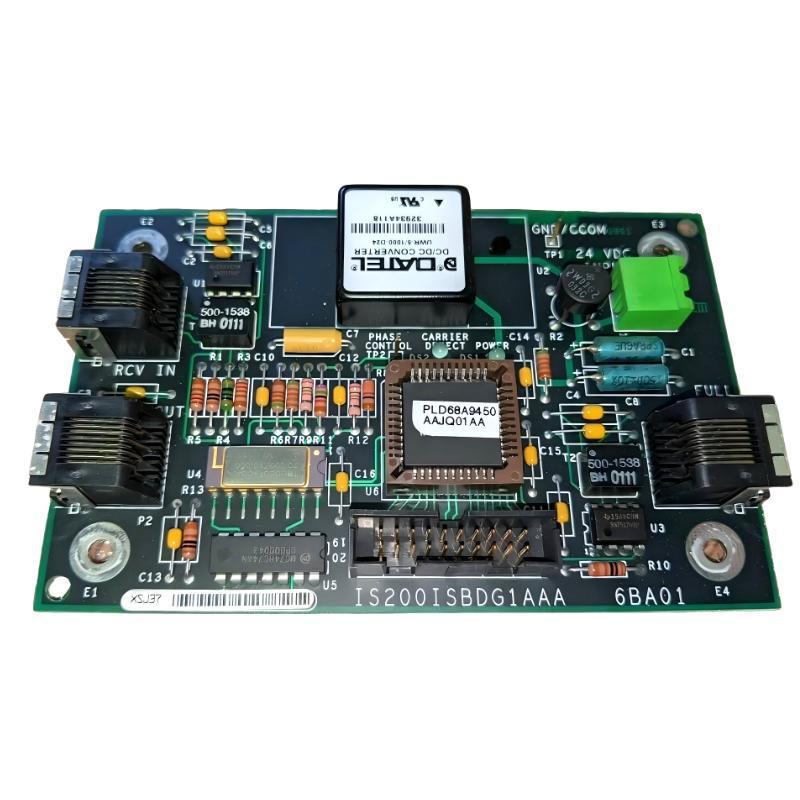
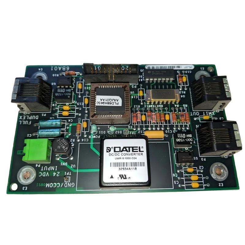
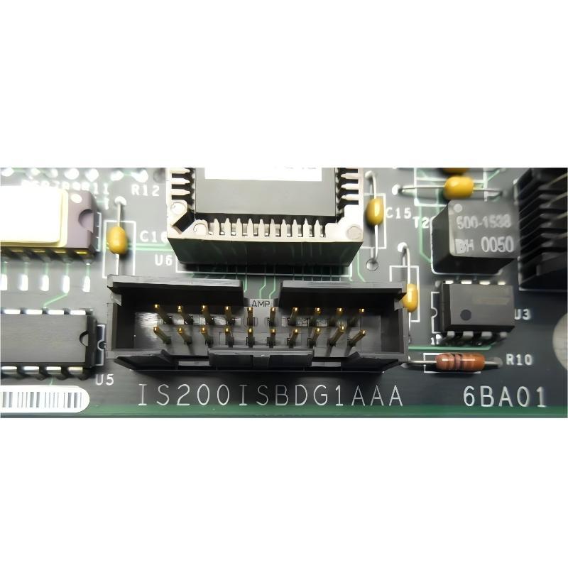
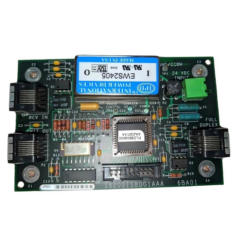
- GE
- IS200ISBDG1AAA
- Synchronous Delay Board
- USA
- 160 × 140 × 35 mm
- 0.454 kg
- Xiamen, China
- New & In Stock
- T/T, PayPal, Western Union
- 1 Year
- 1-3 Working Days
- DHL, UPS, TNT, FedEx and EMS.
- 24-Hour Service
- COO
- 30
Our advantage

Global Logistics
We have a 10-year logistics and express cooperation agreement, so our products can be shipped to any place in the world.

Brand new and original
Our products are imported in bulk from the place of origin. Because of the cooperative relationship, our products are all original and 100% new.

24-hour service
We provide 7*24 hours service to our customers. We will be there whenever you need us.

Price advantage
All our products are priced very favorably because we have our own warehouse and supply.
| Company Information | |||
| [email protected] | |||
| Mobile | +8615980777398 | ||
| +8615980777398 | |||
| 15980777398 |
Product Overview
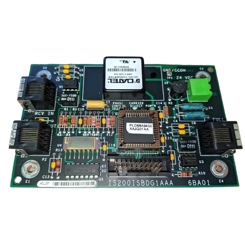
The GE IS200ISBDG1AAA Synchronous Delay Board is an industrial control-system circuit board designed to support timing and synchronization functions within GE automation and control architectures. In systems containing multiple control signals, feedback channels, switching events, or coordinated electronic functions, accurate timing is essential for maintaining predictable system behavior. A synchronous delay board provides a dedicated hardware platform for managing timing relationships between signals within the larger control architecture.
The IS200ISBDG1AAA has a supplied physical size of 160 × 140 × 35 mm and a weight of approximately 0.454 kg. Its compact board-level construction allows it to be integrated into industrial control equipment where multiple electronic assemblies must operate together inside a structured cabinet or rack environment.
Timing coordination is particularly important in industrial systems where several signals must be processed or acted upon in a defined sequence. If signals arrive too early, too late, or with inconsistent timing, the system may experience synchronization errors, unstable operation, incorrect control responses, or diagnostic alarms. The synchronous delay function therefore supports the broader objective of maintaining consistent timing relationships throughout the control architecture.
For replacement applications, the complete GE IS200ISBDG1AAA identification should be verified carefully. Similar GE IS200-series boards can have different electrical functions even when their physical construction appears comparable.
Technical Specifications
| Parameter | Specification |
|---|---|
| Manufacturer | GE |
| Model | IS200ISBDG1AAA |
| Product Type | Synchronous Delay Board |
| Primary Function | Signal timing and synchronization support |
| Application | Industrial control and automation systems |
| Dimensions | 160 × 140 × 35 mm |
| Weight | 0.454 kg |
| Installation | Industrial control cabinet / electronic control assembly |
| Board Type | Timing and control circuit board |
| System Role | Synchronization and controlled signal delay |
| Application Environment | Industrial automation |
| Maintenance | Inspection, signal testing and controlled replacement |
What Is the GE IS200ISBDG1AAA?
The GE IS200ISBDG1AAA is identified as a Synchronous Delay Board. Its purpose is associated with managing the timing relationship between signals within an industrial control system.
In a conventional control architecture, different electronic circuits may receive and process signals at different stages. Even when two signals originate from the same control event, the physical and electronic paths through which they travel can introduce differences in propagation time.
A synchronous delay function helps compensate for or intentionally establish these timing relationships.
A simplified representation is:
Input Signals → Timing Management → Synchronized Signals → Control / Switching Function
The board should therefore be viewed as a timing-support component within a larger system rather than as an independent controller.
Why Synchronous Timing Matters
Industrial control systems frequently depend on coordinated events. A control command may need to correspond with a feedback signal, switching event, measurement, or another control channel.
For example, a simplified coordinated process could involve:
- A control command is generated.
- Multiple signal paths carry related information.
- Electronic circuits process the signals.
- Timing differences are introduced by the system.
- The signals must be synchronized before the next control action.
- The control system evaluates the synchronized information.
If the timing relationship is incorrect, the control system may interpret valid signals incorrectly.
This makes timing hardware particularly important in applications involving:
- Power electronics
- Generator control
- Turbine automation
- Motor drives
- Protection systems
- High-speed control
- Coordinated switching
- Feedback and measurement systems
Function and Working Principle
The exact internal circuit implementation of the IS200ISBDG1AAA should be evaluated according to the particular GE system in which it is installed. At a functional level, a synchronous delay board can be understood through several stages.
Signal Reception
The board receives one or more electrical signals from the surrounding control architecture.
Timing Adjustment
The timing relationship of the relevant signal paths is managed according to the system design. The delay function can establish a predictable relationship between incoming and outgoing signals.
Synchronization
Signals that must correspond to one another can then be presented to downstream circuitry with the required timing relationship.
Signal Transmission
The resulting signals are transferred to the next stage of the control architecture.
The fundamental objective is not simply to make a signal slower. It is to ensure that related signals maintain the correct timing relationship for the application.
Role in Industrial Control Architecture
The GE IS200ISBDG1AAA may operate alongside several different types of control hardware.
A simplified industrial architecture can include:
Sensors / Feedback Devices
↓
Input Interfaces
↓
Signal Processing
↓
Timing and Synchronization
↓
Control Logic
↓
Output Interfaces
↓
Actuators / Power Electronics
A timing board can occupy an important position between signal processing and control functions.
This arrangement allows the overall system to coordinate signals before they are used for critical control decisions.
Applications of the GE IS200ISBDG1AAA
Turbine Control
Turbine systems contain multiple measurement and control functions that must operate in a coordinated manner. Timing consistency can be important when processing speed, position, feedback, and control signals.
Generator Systems
Generator control and associated power electronics can involve coordinated switching and feedback signals. Timing accuracy contributes to predictable control behavior.
Industrial Drives
Drive systems depend on coordinated control of power-switching devices and feedback signals. Timing differences between control channels can affect system behavior.
Power Electronics
Converters, inverters, rectifiers, and other switching systems require precise coordination between control commands and feedback information.
Industrial Automation
Complex automation systems often contain multiple electronic modules communicating with each other. Dedicated timing functions can help maintain predictable signal relationships.
Installation and System Integration
Installation should be performed by qualified industrial automation personnel using the procedures applicable to the associated GE control system.
Verify the Part Number
Confirm the complete identification:
GE IS200ISBDG1AAA
Do not identify the board only by its physical appearance.
Record Existing Connections
Before removing an installed board, document all relevant connectors, cable positions, and mounting locations.
Isolate the Equipment
Place the equipment into the appropriate safe maintenance state and follow established electrical isolation procedures.
Inspect the Replacement Board
Check for:
- Physical damage
- Cracked PCB material
- Bent connectors
- Corrosion
- Contamination
- Signs of overheating
- Damaged mounting points
Install the Board
Position the board correctly and ensure that it is properly secured without applying excessive mechanical force.
Reconnect the System
Restore all relevant cables and connectors to their documented positions.
Controlled Startup
After installation, restore power according to the approved system procedure and monitor the control system for diagnostic abnormalities.
Commissioning and Verification
Because this is a timing-related component, functional verification should go beyond a simple visual inspection.
After installation, maintenance personnel should consider checking:
- System startup diagnostics
- Timing-related alarms
- Signal continuity
- Input and output behavior
- Communication status
- Related control functions
- Abnormal system events
Where the control system provides diagnostic information, compare the system status before and after replacement.
A known-good operating condition should be established before returning equipment to full production service.
Troubleshooting the GE IS200ISBDG1AAA
When a system develops timing or synchronization problems, the IS200ISBDG1AAA should not automatically be identified as the source of the fault.
Timing problems can originate from many locations.
Synchronization Error
Possible causes include:
- Incorrect board installation
- Loose connectors
- Signal wiring problems
- Unstable power
- Faulty upstream electronics
- Faulty downstream equipment
- Incorrect system configuration
- Board-level malfunction
The complete signal path should be examined.
Intermittent Timing Problems
Intermittent faults may be associated with:
- Loose contacts
- Vibration
- Thermal cycling
- Aging components
- Electrical noise
- Power instability
If the problem appears only after the equipment reaches operating temperature, thermal effects should be considered.
Unexpected Control Response
If the system reacts incorrectly to a control event, technicians should determine whether the command itself is incorrect or whether the command reaches the next stage at an unexpected time.
This distinction is important because a timing problem can look like a control-logic problem.
Diagnostic Approach
A practical troubleshooting sequence is:
Step 1: Identify the Symptom
Record exactly what happens, including:
- Alarm description
- Time of occurrence
- Operating condition
- Equipment load
- Temperature
- Related system events
Step 2: Check the Physical Installation
Inspect the board, mounting hardware, and connectors.
Step 3: Verify Power
Confirm that the relevant power source is stable and appropriate for the control assembly.
Step 4: Trace the Signal Path
Follow the affected signal from its source through the control architecture.
Step 5: Compare Related Signals
If multiple channels should be synchronized, compare their behavior and timing characteristics.
Step 6: Review Diagnostics
Use available system-level diagnostic information to determine whether the fault is isolated to the timing circuit or originates elsewhere.
Step 7: Replace Only After Isolation
If the evidence points toward the board, replace it using the appropriate controlled procedure.
Common Failure Causes
Component Aging
Electronic components can deteriorate after years of continuous industrial service.
Thermal Cycling
Repeated temperature changes can place stress on components, solder joints, and connections.
Electrical Transients
Voltage disturbances or unexpected electrical conditions can damage sensitive timing circuitry.
Vibration
Industrial equipment can generate mechanical vibration that affects connectors and board assemblies.
Contamination
Dust and conductive contamination can affect insulation, cooling, and electrical performance.
Moisture
Humidity and condensation can lead to corrosion and leakage paths.
Connector Problems
A timing board can appear defective when the actual problem is caused by a poor electrical connection.
Preventive Maintenance
Preventive maintenance should address both the board and its surrounding control environment.
Recommended practices include:
- Keep control cabinets clean.
- Maintain suitable ventilation.
- Inspect connectors periodically.
- Check for corrosion.
- Monitor abnormal temperatures.
- Review diagnostic history.
- Check for recurring synchronization alarms.
- Inspect mounting hardware.
- Maintain appropriate ESD procedures.
- Keep a correctly identified spare available for critical applications.
Early identification of intermittent timing problems can prevent them from developing into more serious control-system failures.
Replacement Considerations
The supplied physical specifications for the GE IS200ISBDG1AAA are:
Dimensions: 160 × 140 × 35 mm
Weight: 0.454 kg
These specifications are useful for mechanical planning, shipping, storage, and inventory management.
However, physical dimensions should never be used as the sole basis for electrical substitution.
Before ordering or installing a replacement, verify:
- Complete model number
- Board identification
- Revision information
- Connector configuration
- Associated system
- Installation location
- Wiring arrangement
- System compatibility
A similar-looking timing or interface board may have different electrical characteristics.
Spare-Part Management
For facilities operating legacy GE automation systems, maintaining accurate records of timing boards can reduce emergency troubleshooting time.
A recommended inventory record includes:
| Parameter | Record |
|---|---|
| Manufacturer | GE |
| Model | IS200ISBDG1AAA |
| Description | Synchronous Delay Board |
| Dimensions | 160 × 140 × 35 mm |
| Weight | 0.454 kg |
| Application | Industrial control and automation |
| Storage | Clean, dry, ESD-protected environment |
| Installed Location | Cabinet/rack position |
| Condition | New / tested / installed / removed |
| Maintenance History | Record replacement and fault information |
The failure history can also be useful for identifying whether repeated faults are actually caused by environmental or system-level conditions.
Handling and Storage
The IS200ISBDG1AAA should be handled as an electronic industrial control component.
Recommended practices include:
- Use suitable ESD protection.
- Avoid unnecessary contact with conductive surfaces.
- Hold the board carefully.
- Protect connectors from impact.
- Keep the component in suitable packaging when not installed.
- Store it in a clean and dry environment.
- Avoid excessive temperature and humidity.
- Maintain clear part-number identification.
A properly stored spare is much more useful than a spare whose identity or condition is uncertain.
Importance of Accurate Timing in Power Control
In power-control applications, timing errors can have effects beyond the immediate signal path.
Consider a simplified switching sequence:
Control Command → Timing Reference → Gate/Drive Signal → Power Semiconductor → Electrical Output
If the timing reference is inconsistent, the switching event may not occur at the expected point in the control cycle.
This can potentially result in:
- Incorrect switching behavior
- Abnormal feedback
- Increased system stress
- Diagnostic alarms
- Unstable control response
The actual effect depends on the architecture and application, but the principle demonstrates why timing-support hardware deserves the same maintenance attention as more visibly complex control boards.
System-Level Troubleshooting Philosophy
One of the most important principles when maintaining the GE IS200ISBDG1AAA is to avoid replacing components based solely on symptoms.
For example, if a system reports a synchronization error, the fault could originate from:
Power → Wiring → Input Signal → Timing Board → Control Logic → Output Circuit
A disciplined technician should progressively eliminate each possible source.
This method reduces unnecessary replacement costs and prevents repeated failures caused by an unresolved external problem.
Key Advantages
Dedicated Timing Function
The IS200ISBDG1AAA is designed around synchronous delay functionality within an industrial control architecture.
Compact Construction
The supplied 160 × 140 × 35 mm dimensions make it suitable for integration into industrial electronic assemblies.
Lightweight Design
At approximately 0.454 kg, the board is relatively easy to handle during maintenance and replacement operations.
Supports Coordinated Control
Timing management can help maintain consistent relationships between related control signals.
Suitable for Industrial System Maintenance
Accurately identified replacement boards can support the continued operation of established GE automation installations.
Technical FAQs
What is the GE IS200ISBDG1AAA?
The GE IS200ISBDG1AAA is a Synchronous Delay Board associated with timing and synchronization functions in industrial control systems.
What are the dimensions of the IS200ISBDG1AAA?
The supplied dimensions are 160 × 140 × 35 mm.
What is the weight of the IS200ISBDG1AAA?
The supplied weight is 0.454 kg.
What does a synchronous delay board do?
It supports the controlled timing relationship between signals so that related control or feedback signals can be coordinated correctly within a larger system.
Is the IS200ISBDG1AAA a standalone controller?
No. It is a specialized timing-related board that operates as part of a larger industrial control architecture.
What can cause synchronization problems?
Possible causes include power instability, wiring problems, connector faults, component aging, vibration, thermal stress, configuration problems, or failures elsewhere in the control system.
Can another IS200 board automatically replace the IS200ISBDG1AAA?
No. Similar physical dimensions do not guarantee functional or electrical compatibility. The complete model and system configuration must be verified.
How should a spare IS200ISBDG1AAA be stored?
It should be protected from ESD, moisture, contamination, impact, and excessive environmental conditions while retaining clear model identification.
Conclusion
The GE IS200ISBDG1AAA Synchronous Delay Board is a specialized industrial control component associated with signal timing and synchronization. In a complex automation architecture, maintaining accurate timing relationships between control, feedback, and switching signals can be essential for predictable system operation.
The supplied dimensions of the IS200ISBDG1AAA are 160 × 140 × 35 mm, with a weight of 0.454 kg. These specifications make the board relatively compact and lightweight for industrial control-system installation and spare-part management.
When troubleshooting a synchronization problem, technicians should evaluate the entire signal path rather than immediately assuming that the timing board has failed. Power quality, wiring, connectors, upstream electronics, downstream circuits, environmental conditions, and configuration can all influence system behavior.
For replacement applications, the complete GE IS200ISBDG1AAA identification should be verified before installation. Proper handling, preventive inspection, accurate diagnostics, and controlled replacement procedures can help maintain the reliability of GE industrial automation and control equipment.