

ProductPRODUCT
Featured products



Contact Us
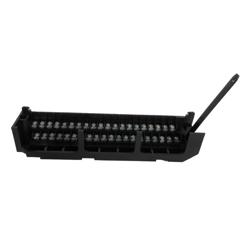
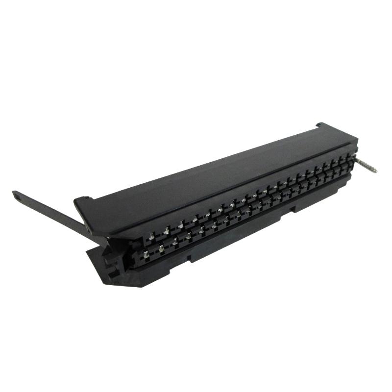
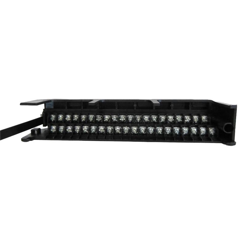
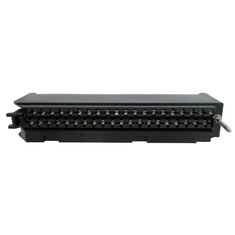
- GE
- IC697ACC700
- Terminal Block
- USA
- 12 × 100 × 55 mm
- 1.79 kg
- Xiamen, China
- New & In Stock
- T/T, PayPal, Western Union
- 1 Year
- 1-3 Working Days
- DHL, UPS, TNT, FedEx and EMS.
- 24-Hour Service
- COO
- 76
Our advantage

Global Logistics
We have a 10-year logistics and express cooperation agreement, so our products can be shipped to any place in the world.

Brand new and original
Our products are imported in bulk from the place of origin. Because of the cooperative relationship, our products are all original and 100% new.

24-hour service
We provide 7*24 hours service to our customers. We will be there whenever you need us.

Price advantage
All our products are priced very favorably because we have our own warehouse and supply.
| Company Information | |||
| [email protected] | |||
| Mobile | +8615980777398 | ||
| +8615980777398 | |||
| 15980777398 |
Product Overview
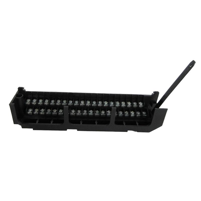
The GE IC697ACC700 Terminal Block is a wiring and connection component used in industrial control system applications associated with GE programmable controller equipment. Its primary purpose is to provide a structured interface for connecting field wiring to compatible control, I/O, or interface circuitry.
Terminal blocks are an important part of industrial automation installations because they provide an organized transition between field devices and control-system wiring. A properly installed terminal block helps simplify cabinet wiring, improve maintenance accessibility, and reduce the possibility of wiring errors during commissioning or troubleshooting.
The supplied physical specifications for the GE IC697ACC700 are 12 × 100 × 55 mm, with a listed weight of 1.79 kg. Because terminal-block configurations can vary according to the associated controller, I/O module, connector arrangement, and cabinet design, the complete system configuration should be checked before replacement or installation.
Product Identification
| Parameter | Specification |
|---|---|
| Manufacturer | GE |
| Model | IC697ACC700 |
| Product Type | Terminal Block |
| Product Category | Industrial Control Wiring Component |
| Primary Function | Field Wiring and Signal Termination |
| Dimensions | 12 × 100 × 55 mm |
| Weight | 1.79 kg |
| Installation | Industrial Control Cabinet |
| Application | PLC / Industrial Automation Systems |
| Maintenance Type | Wiring Inspection and Replacement |
Technical Specifications
| Technical Item | Specification |
|---|---|
| Brand | GE |
| Model Number | IC697ACC700 |
| Product Category | Terminal Block |
| Function | Electrical Signal Termination |
| Interface Type | Field Wiring Interface |
| Dimensions | 12 × 100 × 55 mm |
| Weight | 1.79 kg |
| Installation Environment | Industrial Control Panel |
| Application | Programmable Control Systems |
| Service Requirement | Periodic Inspection |
| Replacement Method | Wiring-Compatible Component Replacement |
What Is a Terminal Block?
A terminal block is an electrical connection interface used to organize and secure multiple wires within a control cabinet.
In a PLC system, the wiring architecture can typically be represented as:
Field Sensor / Actuator
↓
Field Cable
↓
Terminal Block
↓
I/O or Control Module
↓
PLC CPU
↓
Control Logic
The terminal block provides a physical connection point between field wiring and control-system wiring.
Depending on the system design, it can also make troubleshooting easier because individual signal circuits can be identified and tested without disturbing the complete control system.
Main Functions
Field Wiring Termination
Provides a structured point for connecting field conductors.
Wiring Organization
Helps organize multiple signal circuits inside an industrial control cabinet.
Maintenance Accessibility
A clearly organized terminal arrangement can simplify troubleshooting and replacement work.
Signal Identification
Proper labeling allows technicians to quickly identify individual circuits.
Cabinet Wiring Management
Terminal blocks help separate field wiring from internal control wiring and can improve cabinet organization.
Typical Applications
The GE IC697ACC700 may be used as part of industrial automation wiring arrangements involving compatible GE control equipment.
Typical applications include:
Manufacturing
- Production machinery
- Assembly lines
- Packaging systems
- Conveyor controls
Process Automation
- Instrumentation
- Process monitoring
- Valve control
- Pump control
Power Systems
- Auxiliary control
- Monitoring systems
- Electrical equipment interfaces
Water Treatment
- Pump stations
- Flow monitoring
- Level control
- Treatment equipment
Installation Guide
1. Verify the Terminal Block
Before installation, verify:
- Model number
- Associated equipment
- Wiring configuration
- Terminal arrangement
- Cabinet location
- Replacement requirements
The IC697ACC700 should be matched to the existing system configuration rather than selected solely by physical dimensions.
2. De-Energize the Control Cabinet
Before working on terminal connections:
- Shut down the associated control system.
- Disconnect electrical power.
- Isolate external field power.
- Follow lockout/tagout procedures.
- Verify that the relevant circuits are de-energized.
Do not assume that all terminal circuits are safe simply because the PLC CPU is switched off.
3. Document Existing Wiring
Before removing an existing terminal block, record:
- Wire numbers
- Terminal numbers
- Signal names
- Cable identification
- Jumper positions
- Shield connections
Clear documentation greatly reduces the risk of incorrect reconnection.
4. Inspect Existing Wiring
Check the connected wires for:
- Damaged insulation
- Loose conductors
- Corrosion
- Broken strands
- Excessive bending
- Incorrect labeling
Repair defective wiring before installing the replacement terminal block.
5. Remove the Existing Terminal Block
Carefully disconnect the field wiring according to the applicable maintenance procedure.
Avoid pulling wires excessively.
Keep wires organized so that they can be reconnected to their original terminals.
6. Install the IC697ACC700
Position the terminal block correctly within the control cabinet or designated installation location.
Verify:
- Correct orientation
- Secure mechanical mounting
- Adequate clearance
- No cable interference
The supplied dimensions are:
12 × 100 × 55 mm
The supplied weight is:
1.79 kg
7. Reconnect Wiring
Reconnect each conductor according to the documented wiring arrangement.
Pay particular attention to:
- Terminal numbers
- Polarity
- Signal type
- Common connections
- Shielding
- Grounding
Incorrect wiring can cause equipment malfunction or damage.
8. Tighten Connections
Secure each terminal connection according to the applicable terminal hardware requirements.
Avoid both:
- Under-tightening
- Excessive tightening
A loose connection can cause intermittent faults, while excessive tightening may damage the terminal or conductor.
9. Inspect the Completed Wiring
After reconnecting the wires, verify:
- No loose conductors
- No exposed copper beyond acceptable limits
- Correct wire routing
- Correct labels
- No accidental shorts
- Proper shield termination
10. Restore Power and Test
After completing installation:
- Perform a final wiring inspection.
- Restore control power.
- Restore field power where applicable.
- Start the controller.
- Monitor I/O status.
- Test connected field devices.
Commissioning Verification
After installation, verify:
Digital Inputs
Confirm that field switches and sensors generate the expected PLC input states.
Digital Outputs
Confirm that commanded outputs operate the intended devices.
Analog Signals
Where applicable, verify signal values and scaling.
Communication
Confirm that connected control equipment communicates normally.
Alarms
Verify that no unexpected diagnostics or field alarms are generated.
Troubleshooting Guide
One Signal Does Not Work
Possible causes include:
- Loose terminal connection
- Broken field wire
- Incorrect terminal assignment
- Sensor failure
- I/O channel problem
Begin troubleshooting at the field device and follow the signal path toward the PLC.
Intermittent Signal
Intermittent faults are frequently associated with:
- Loose terminal connections
- Damaged conductors
- Vibration
- Corrosion
- Poor cable termination
Inspect the terminal connection while monitoring the affected signal.
Multiple Signals Fail Simultaneously
If several signals connected through the same terminal interface fail at the same time, inspect:
- Common wiring
- Power supply
- Grounding
- Shared terminals
- I/O module
- Field power
Multiple simultaneous failures are less likely to be caused by individual field devices.
Incorrect Signal Reading
Possible causes include:
- Incorrect wire assignment
- Poor terminal connection
- Signal polarity error
- Grounding problem
- Incorrect I/O configuration
Verify the complete signal circuit from the field device to the PLC.
Output Device Does Not Operate
Possible causes:
- Loose output wiring
- Incorrect terminal assignment
- Output channel fault
- External power failure
- Device failure
Check the PLC output status first, then trace the physical circuit through the terminal block.
Terminal Connection Overheats
Possible causes include:
- Loose connection
- Excessive current
- Incorrect conductor size
- Corrosion
- Damaged terminal
Disconnect power and investigate the cause before returning the circuit to service.
Visible Corrosion
Corrosion may result from:
- Moisture
- Chemical contamination
- High humidity
- Poor enclosure sealing
Replace damaged components and correct the environmental cause.
Preventive Maintenance
Visual Inspection
Regularly inspect:
- Terminal housing
- Wire insulation
- Terminal connections
- Labels
- Cable routing
Connection Inspection
Check for:
- Loose terminals
- Corrosion
- Discoloration
- Signs of overheating
Environmental Inspection
Maintain appropriate control cabinet conditions.
Pay particular attention to:
- Humidity
- Dust
- Condensation
- Chemical contamination
- Excessive vibration
Maintenance Checklist
| Inspection Item | Status |
|---|---|
| Terminal Block Model Verified | ✓ |
| Cabinet Power Isolated | ✓ |
| Field Power Isolated | ✓ |
| Wiring Documented | ✓ |
| Terminal Connections Inspected | ✓ |
| Conductors Checked | ✓ |
| Mounting Verified | ✓ |
| Wiring Reconnected | ✓ |
| Terminal Connections Secured | ✓ |
| Signal Testing Completed | ✓ |
| Field Devices Tested | ✓ |
| Final Inspection Completed | ✓ |
Recommended Replacement Considerations
When replacing an IC697ACC700, technicians should verify more than the physical dimensions.
Important considerations include:
| Check Item | Reason |
|---|---|
| Model Number | Confirms component identity |
| Terminal Arrangement | Prevents wiring errors |
| Associated I/O Hardware | Ensures system compatibility |
| Wire Numbering | Maintains signal traceability |
| Signal Type | Prevents incorrect connections |
| Mounting Arrangement | Ensures mechanical compatibility |
| Electrical Rating | Ensures safe operation |
| Cabinet Environment | Supports long-term reliability |
Compatible System Components
The terminal block functions as part of a larger control-system architecture.
| Component | Function |
|---|---|
| PLC CPU | Executes Control Logic |
| I/O Module | Processes Field Signals |
| Power Supply | Provides System Power |
| Terminal Block | Provides Wiring Interface |
| Field Sensor | Measures Process Conditions |
| Actuator | Performs Physical Control |
| Control Cabinet | Houses Automation Equipment |
| Field Wiring | Transmits Electrical Signals |
The exact compatible components should be confirmed against the particular control-system configuration.
Key Advantages
Organized Field Wiring
Provides a structured connection point for industrial control wiring.
Easier Troubleshooting
Clearly organized terminal connections simplify signal tracing and fault diagnosis.
Improved Maintenance
A dedicated wiring interface makes replacement and inspection more manageable.
Compact Physical Format
The supplied dimensions of 12 × 100 × 55 mm allow installation in space-constrained control panels.
Industrial Automation Application
Suitable for wiring architectures associated with PLC and industrial control systems.
Frequently Asked Questions
What is the GE IC697ACC700?
The IC697ACC700 is a Terminal Block used as a field-wiring interface in compatible GE industrial control system configurations.
What are its dimensions?
The supplied dimensions are:
12 × 100 × 55 mm
What is its weight?
The supplied weight is:
1.79 kg
What is the primary purpose of a terminal block?
It provides an organized and secure connection point between field wiring and control-system equipment.
Can the terminal block be replaced without shutting down the system?
Work on control-system terminal wiring should normally be performed with the relevant electrical circuits isolated and verified de-energized. Follow the applicable plant safety procedure.
What causes intermittent terminal faults?
Common causes include loose connections, damaged wires, vibration, corrosion, and poor termination.
Why should wiring be documented before replacement?
Documentation helps ensure every conductor is returned to the correct terminal and greatly reduces commissioning errors.
What should be checked after replacement?
Verify terminal assignments, connection security, polarity, grounding, signal continuity, I/O status, and field-device operation.
Installation Checklist
| Item | Status |
|---|---|
| Correct IC697ACC700 Identified | ✓ |
| Associated Equipment Verified | ✓ |
| Power Isolated | ✓ |
| Existing Wiring Documented | ✓ |
| Wires Identified | ✓ |
| Existing Terminal Removed | ✓ |
| New Terminal Block Installed | ✓ |
| Wiring Reconnected | ✓ |
| Connections Secured | ✓ |
| Polarity Verified | ✓ |
| I/O Signals Tested | ✓ |
| Final Inspection Completed | ✓ |
Conclusion
The GE IC697ACC700 Terminal Block provides an important physical interface between field wiring and compatible industrial automation equipment. Although it is a relatively simple component compared with a PLC CPU or I/O module, the quality and reliability of terminal connections have a direct impact on signal integrity, equipment availability, and maintenance efficiency.
The supplied IC697ACC700 specifications are 12 × 100 × 55 mm and 1.79 kg. During installation or replacement, technicians should verify the complete wiring arrangement, terminal assignment, associated equipment, and electrical requirements rather than relying solely on physical dimensions.
Proper wiring documentation, secure terminal connections, correct grounding, and regular visual inspection can significantly reduce intermittent faults and signal failures. When correctly integrated into the control cabinet, the IC697ACC700 helps provide an organized and maintainable wiring interface for industrial PLC and automation applications.