

ProductPRODUCT
Featured products

Contact Us
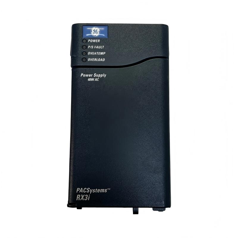
- GE
- IC695PSA040J
- RX3i Universal Backplane Power Supply
- USA
- 135 × 71 × 127 mm
- 0.522 kg
- Xiamen, China
- New & In Stock
- T/T, PayPal, Western Union
- 1 Year
- 1-3 Working Days
- DHL, UPS, TNT, FedEx and EMS.
- 24-Hour Service
- COO
- 3
Our advantage

Global Logistics
We have a 10-year logistics and express cooperation agreement, so our products can be shipped to any place in the world.

Brand new and original
Our products are imported in bulk from the place of origin. Because of the cooperative relationship, our products are all original and 100% new.

24-hour service
We provide 7*24 hours service to our customers. We will be there whenever you need us.

Price advantage
All our products are priced very favorably because we have our own warehouse and supply.
| Company Information | |||
| [email protected] | |||
| Mobile | +8615980777398 | ||
| +8615980777398 | |||
| 15980777398 |
Product Overview
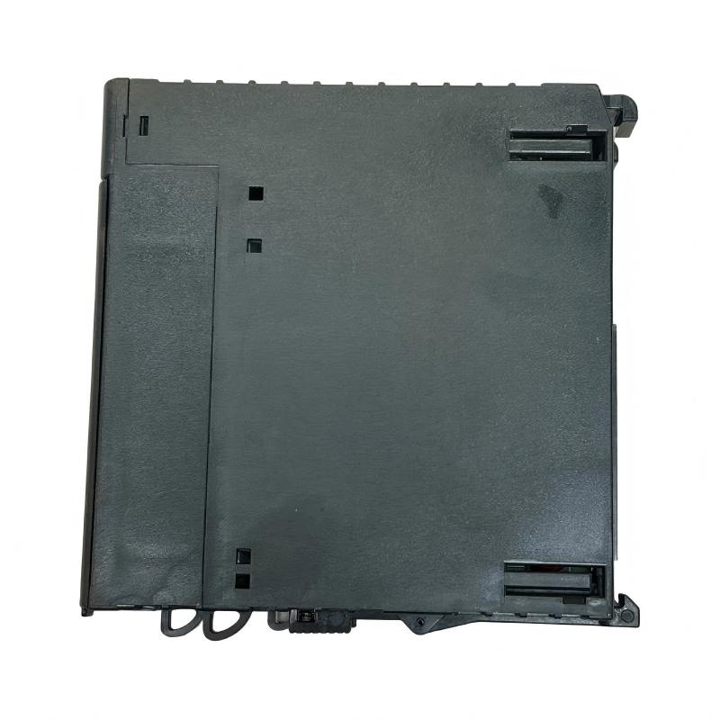
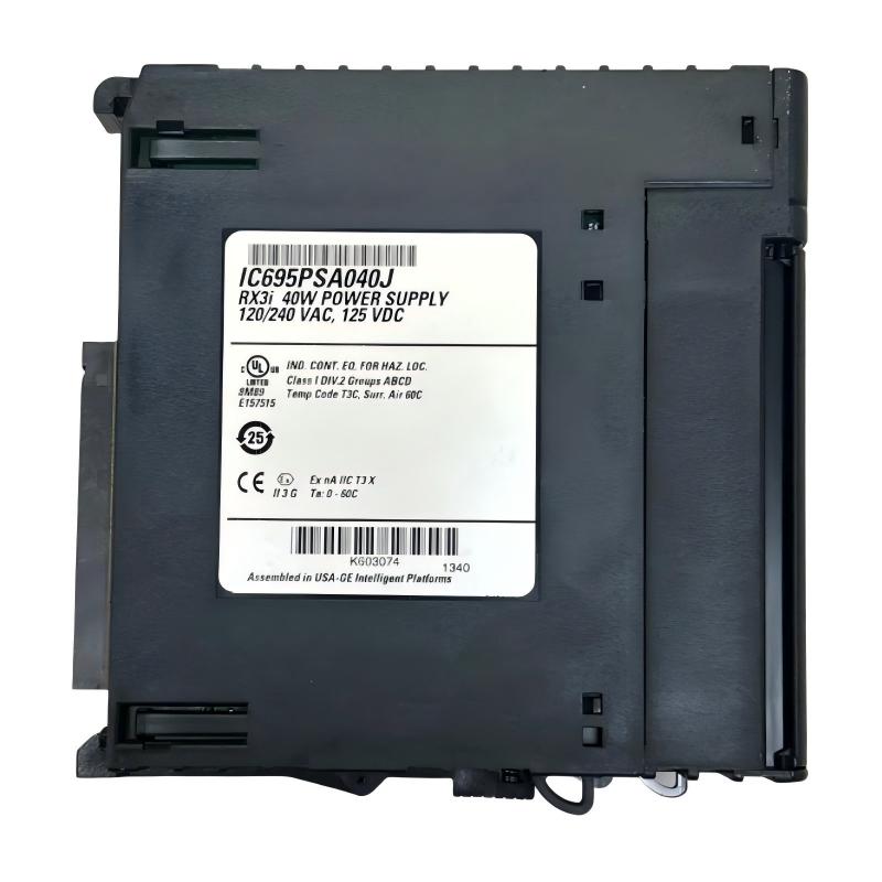
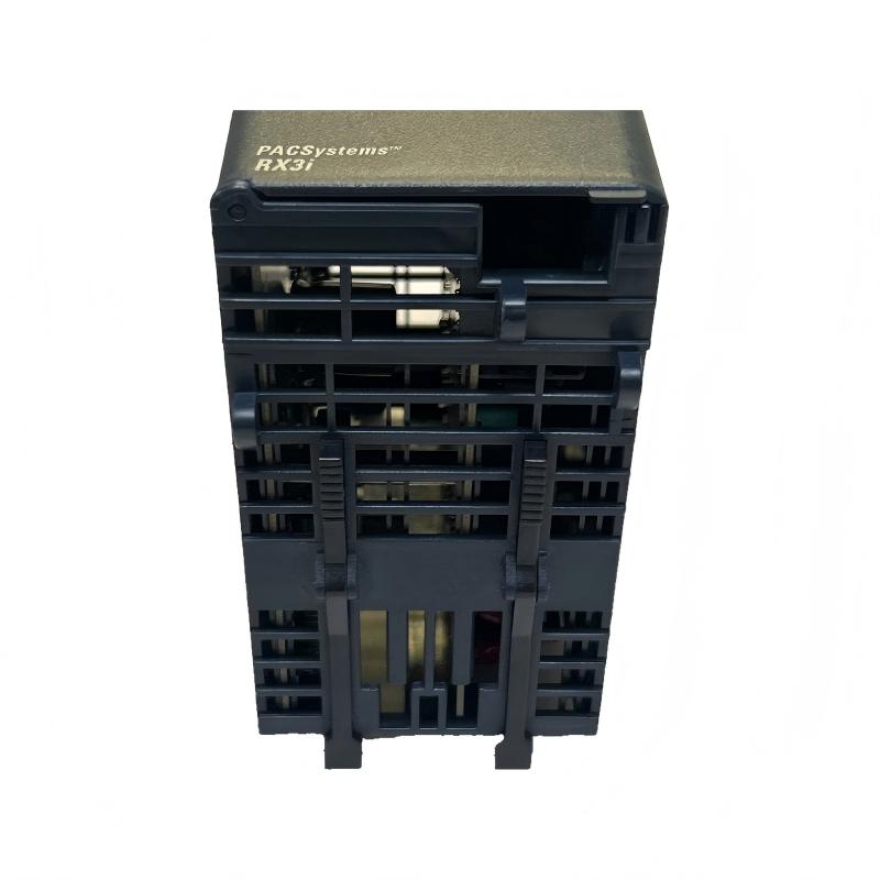
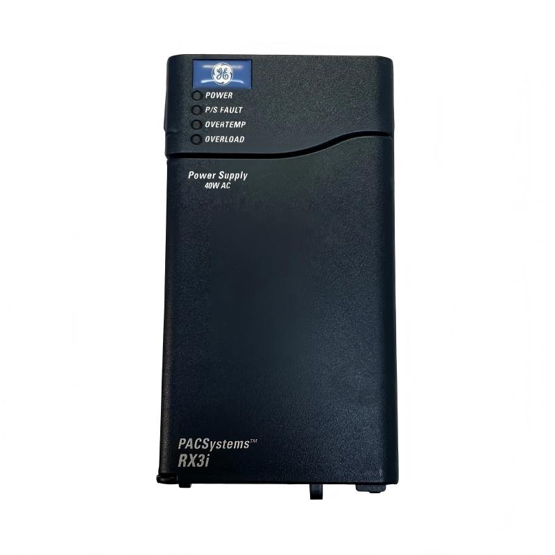
The GE IC695PSA040J RX3i Universal Backplane Power Supply is an industrial automation power supply designed for use within a compatible GE PACSystems RX3i programmable automation controller (PAC) system. Its primary role is to provide the electrical power required by the controller backplane and installed automation modules, supporting stable operation of the system’s processing, input/output, and communication components.
In an industrial control cabinet, the power supply is a critical part of the automation architecture. The controller CPU, I/O modules, communication interfaces, and other backplane-mounted components depend on an appropriate power source to operate correctly. A suitable backplane power supply helps maintain consistent system operation and supports reliable communication between the controller and its connected modules.
The IC695PSA040J belongs to the GE RX3i product family and is identified by the supplied description as a universal backplane power supply. Its listed dimensions are 135 × 71 × 127 mm, and its listed weight is 0.522 kg. This compact form factor supports installation in appropriately configured industrial control systems where space, power distribution, and maintainability are important considerations.
The complete model number should be verified before installation or replacement. The exact input voltage range, output ratings, supported backplane configurations, diagnostic functions, and hardware compatibility must be confirmed against the applicable specifications for the IC695PSA040J revision.
Technical Specifications
| Parameter | Specification |
|---|---|
| Manufacturer | General Electric (GE) |
| Model Number | IC695PSA040J |
| Product Family | PACSystems RX3i |
| Product Type | Universal Backplane Power Supply |
| Primary Function | Supplies power to a compatible controller backplane |
| System Category | Industrial PLC / PAC Power Supply |
| Application | Industrial automation and control systems |
| Dimensions | 135 × 71 × 127 mm |
| Weight | 0.522 kg |
| Installation | Compatible RX3i backplane or specified mounting arrangement |
| Input Voltage | Verify the exact model specification |
| Output Ratings | Verify the applicable hardware documentation |
| Protection and Diagnostics | Confirm supported functions for the installed revision |
| Compatibility | Verify against the RX3i backplane, CPU, and module configuration |
The table separates the supplied identification and physical measurements from electrical details that require model-specific verification. Input voltage, output capacity, terminal assignments, and supported configurations should not be inferred from the product name alone.
What Is the GE IC695PSA040J?
The IC695PSA040J is identified as a power supply for the GE PACSystems RX3i automation platform. A backplane power supply provides the electrical energy needed by compatible components installed within the controller rack or backplane assembly.
In a programmable automation system, the CPU executes the control program, input modules collect field signals, output modules issue control commands, and communication modules exchange information with other devices. These components require an appropriately rated power source to function within their specified operating limits.
The backplane power supply supports this electrical infrastructure. It does not replace the CPU or perform the control logic itself. Instead, it provides a foundation for the operation of the installed automation hardware.
A simplified system arrangement is:
Incoming Power → RX3i Power Supply → Compatible Backplane → CPU, I/O and Communication Modules → Industrial Control Process
The actual power path, permitted module combinations, and installation requirements depend on the verified hardware configuration.
Function and Working Principle
1. Electrical Power Conversion
Industrial control systems require power that meets the electrical requirements of their internal electronic components. A backplane power supply receives an appropriate input and provides the required power to the supported system.
The precise input range and output characteristics of the IC695PSA040J should be confirmed before connecting the unit to an electrical source. Using an incompatible supply can cause startup problems, system faults, or damage to installed hardware.
2. Backplane Power Distribution
Once operating within its specified conditions, the power supply provides power through the supported backplane arrangement. The backplane distributes electrical connections to the installed controller modules.
This arrangement reduces the need for separate external power connections to every compatible backplane-mounted component, subject to the system’s design.
3. Support for Controller Operation
The CPU and other installed modules rely on an adequate power supply to initialize and perform their intended functions. A suitable supply helps establish the electrical conditions required for the controller to start and operate normally.
If the supply is missing, overloaded, incorrectly connected, or incompatible with the system, the controller may fail to start or may report hardware-related faults.
4. System Availability
Power-related faults can affect multiple modules at once. For this reason, checking the backplane power supply is an important step when diagnosing a controller that will not start, experiences repeated resets, or reports several module faults simultaneously.
The supply should be evaluated alongside the input source, backplane, installed modules, wiring, and system diagnostics rather than being assumed to be the cause of every controller fault.
Role in GE RX3i Industrial Automation Systems
The GE IC695PSA040J provides a power-related function within a compatible RX3i control architecture. In a typical automation installation, the controller system connects field devices and industrial equipment with the software logic that manages machine or process operation.
The backplane power supply supports the hardware layer on which these functions depend.
| System Component | Typical Role |
|---|---|
| IC695PSA040J Power Supply | Provides power to a compatible backplane |
| RX3i Backplane | Provides the mounting and electrical interconnection for supported modules |
| Compatible CPU | Executes the control program |
| Digital Input Module | Receives discrete signals from switches and sensors |
| Digital Output Module | Provides discrete output signals to compatible interface devices |
| Analog Input Module | Acquires supported continuous process signals |
| Analog Output Module | Provides supported variable control signals |
| Communication Module | Connects compatible automation devices and networks |
| HMI | Displays operating status, alarms, and process information |
| Engineering Workstation | Supports configuration, programming, and diagnostics |
The exact module combination must be checked against the applicable RX3i hardware documentation. A module’s physical fit alone does not establish electrical or functional compatibility.
Industrial Applications
Manufacturing and Production Lines
Manufacturing systems depend on PLCs and PACs to coordinate equipment sequences, monitor machine states, and control production operations. A suitable backplane power supply supports the operation of the installed automation hardware.
Process Automation
Process-control installations may use controller systems to monitor and regulate equipment such as pumps, valves, motors, and material-handling devices. Reliable controller power is essential for the operation of the associated monitoring and control hardware.
Water and Wastewater Facilities
Water-treatment and wastewater systems often incorporate automated pumping, filtration, dosing, and monitoring equipment. Where a compatible RX3i system is installed, the power supply contributes to the electrical infrastructure supporting the controller and its modules.
Material Handling
Conveyors, transfer stations, and other material-handling systems use controllers to coordinate discrete operations and equipment feedback. A properly configured backplane power supply supports the control hardware used for these tasks.
Industrial Utilities
Utility installations may use PLC systems for equipment monitoring, alarm handling, and operational sequencing. Stable power for the control backplane helps support the availability of these functions.
Distributed Industrial Control
Some industrial facilities use several controllers and remote or distributed I/O arrangements. The IC695PSA040J should only be used in the specific compatible hardware arrangement for which it is rated; it should not be assumed to power every type of remote I/O or external field device.
Installation and System Integration
Correct installation is essential for safe and reliable operation. Before installing or replacing the IC695PSA040J, verify the exact hardware designation, electrical requirements, and permitted system configuration.
Confirm the Model and Revision
Check the product label and confirm the complete order number, IC695PSA040J. Compare it with the existing unit, the system hardware list, and the applicable installation documentation.
If the replacement differs from the installed unit, verify whether the proposed revision is approved for the existing backplane and module arrangement.
Verify the Input Power Requirements
Before connecting the supply, confirm the required input voltage, frequency where applicable, terminal assignments, grounding requirements, and protective-device recommendations.
Do not select the incoming power source based only on the phrase “universal power supply.” The exact permitted input range must be verified for the specific model.
Inspect the Backplane
Before installation, inspect the compatible backplane for damaged connectors, contamination, loose mounting hardware, or signs of overheating. A damaged backplane can cause problems that are not resolved by replacing the power supply.
Confirm that the unit is correctly seated and secured using the specified installation procedure.
Check the Module Load
Review the installed CPU, I/O modules, communication interfaces, and other backplane components. Confirm that the total power demand and configuration remain within the supply’s supported limits.
Adding modules or changing the rack configuration without checking power requirements can lead to overloads or unreliable operation.
Follow Electrical Safety Procedures
Isolate the equipment according to the site’s lockout and tagout procedures before replacing the supply. Verify the absence of hazardous voltage using appropriate equipment and qualified procedures.
Follow the manufacturer’s instructions for handling the power supply and protecting exposed electronic components from electrostatic discharge.
Commission the System
After installation, verify that the supply starts normally and that the controller and installed modules reach their expected operating states. Review available status indicators and controller diagnostics.
Confirm that the system recognizes the installed hardware and that no new power-related or configuration faults appear. Record the replacement details and commissioning results for future maintenance.
Troubleshooting the IC695PSA040J Power Supply
Power-supply troubleshooting should consider the complete electrical and controller system. The following checks provide a general diagnostic approach; model-specific indicators and test procedures must be confirmed from the applicable documentation.
Controller Does Not Start
If the controller fails to start, possible causes include:
- Missing or incorrect input power
- Loose or incorrect power connections
- A failed power supply
- A damaged or improperly seated backplane
- An incompatible module configuration
- Excessive backplane load
- A fault in another installed component
Begin by checking the input source and wiring. Confirm that the supply receives the specified input and inspect the backplane and module seating. Use the approved diagnostic procedure to determine whether the power supply is functioning correctly.
Multiple Modules Report Faults
When several modules develop faults at the same time, investigate shared resources before replacing individual modules. A power-supply problem, backplane issue, or incorrect system configuration can affect multiple components.
Record the fault messages and status indicators, then check the supply and backplane against the applicable system requirements.
Power Supply Fails to Remain Operational
Repeated shutdowns or unstable operation may be associated with an unsuitable input source, overload, poor connections, excessive temperature, or a hardware fault.
Check the input supply under appropriate conditions and confirm that the installed module load is within the specified limits. Do not bypass protective functions or continue operating equipment with unexplained power instability.
Overheating or Abnormal Odor
Unexpected heat, discoloration, smoke, or a burning odor can indicate an electrical or component failure. If these conditions occur, isolate the equipment safely and follow the site’s incident and maintenance procedures.
Do not continue energizing a suspect supply merely to observe whether the problem repeats.
Faults Persist After Replacement
If replacing the power supply does not resolve the problem, investigate the incoming power source, backplane, connected modules, wiring, and configuration.
Confirm that the replacement has the correct order number and is approved for the installed system. A replacement that physically fits may still be electrically or functionally unsuitable.
Maintenance Recommendations
Inspect Power Connections
Check accessible connections for looseness, corrosion, discoloration, or other signs of deterioration during scheduled maintenance. Perform inspections only under the required safe isolation conditions.
Maintain Cabinet Conditions
Keep the control cabinet within the specified environmental limits. Excessive heat, dust, moisture, and restricted airflow can shorten the service life of electronic equipment.
Review System Diagnostics
Record recurring power-related alarms, controller resets, and module faults. A pattern of simultaneous faults can help distinguish a shared power problem from an isolated module failure.
Review Changes to the Hardware Configuration
Whenever modules are added, removed, or replaced, confirm that the resulting configuration remains within the power supply’s permitted operating limits.
Maintain Replacement Records
Record the complete model number, revision, installation date, observed fault symptoms, and commissioning results. Accurate maintenance records help reduce identification errors during future repairs.
Compatible System Components
The IC695PSA040J should be integrated only with components confirmed as compatible with the specific RX3i configuration. The following table describes common functional roles in an industrial controller system rather than guaranteeing compatibility with every individual product.
| Component Category | Purpose |
|---|---|
| Compatible RX3i Backplane | Provides module mounting and electrical interconnection |
| Supported RX3i CPU | Executes the automation program |
| Compatible Digital I/O Modules | Handle discrete field signals |
| Compatible Analog I/O Modules | Handle supported analog signals |
| Supported Communication Modules | Provide the required industrial communication interfaces |
| Industrial Circuit Protection | Provides appropriately designed input-side protection |
| Control Cabinet | Provides the required mounting and environmental protection |
| HMI or Operator Station | Presents process status and alarms |
| Engineering Workstation | Supports system configuration and diagnostics |
Before purchasing additional modules, confirm the supported hardware combination, revision requirements, power budget, and installation instructions.
Replacement and Procurement Considerations
When sourcing a replacement for the GE IC695PSA040J RX3i Universal Backplane Power Supply, correct identification is essential.
Check the following details before ordering:
- Complete order number: IC695PSA040J
- Hardware revision
- Product condition and inspection records
- Input power requirements
- Output and backplane power ratings
- Compatibility with the installed RX3i backplane
- Total load of the installed modules
- Mounting and connection requirements
The supplied physical dimensions are 135 × 71 × 127 mm, and the supplied weight is 0.522 kg. These measurements can assist with stock management, shipping estimates, and preliminary installation planning.
Dimensions and weight should not be treated as evidence of electrical interchangeability. A suitable replacement must meet the system’s electrical, mechanical, and configuration requirements.
Key Advantages
Supports Controller Backplane Power
The power supply provides the electrical foundation needed by compatible backplane-mounted automation hardware.
Contributes to System Reliability
A correctly selected and maintained power supply helps reduce power-related interruptions and supports stable controller operation.
Compact Physical Design
The listed dimensions of 135 × 71 × 127 mm and weight of 0.522 kg support practical handling and inventory planning for suitable installations.
Supports Modular Automation Architecture
Within an approved RX3i configuration, the power supply supports the operation of the controller and its associated modules.
Simplifies Power-System Maintenance
Clear hardware identification and documented power requirements help technicians diagnose faults, verify replacements, and maintain a consistent controller configuration.
Technical FAQs
What is the GE IC695PSA040J?
The IC695PSA040J is identified as a GE PACSystems RX3i universal backplane power supply. Its primary role is to provide power to a compatible controller backplane and the supported modules installed within the system.
What are the dimensions of the IC695PSA040J?
The supplied dimensions are 135 × 71 × 127 mm.
How much does the IC695PSA040J weigh?
The supplied weight is 0.522 kg.
Does this power supply execute PLC logic?
No. A power supply provides electrical power. The compatible CPU executes the control program, while I/O and communication modules perform their respective functions.
Can the IC695PSA040J be installed in any GE PLC rack?
No. Compatibility must be verified against the exact backplane, controller family, module arrangement, and applicable hardware documentation. A shared manufacturer or similar physical appearance does not guarantee compatibility.
What should be checked if the controller will not start?
Check the input power source, wiring, supply status, backplane condition, installed module load, and controller diagnostics. Follow the approved procedures for testing the supply and isolating possible faults.
Can another RX3i power supply replace the IC695PSA040J?
A different power supply should not be assumed to be interchangeable. Verify input requirements, output ratings, supported backplane configuration, revision compatibility, and the total power demand of the installed modules.
Why is the backplane power supply important?
The backplane power supply supports the operation of the controller and its installed modules. If it cannot provide the required power, the system may fail to start, report multiple hardware faults, or operate unreliably.
Conclusion
The GE IC695PSA040J RX3i Universal Backplane Power Supply is an industrial automation power component intended to support a compatible GE PACSystems RX3i controller configuration. By supplying power to the backplane and its supported modules, it provides an essential foundation for PLC processing, field-signal acquisition, communication, and automated equipment control.
With listed dimensions of 135 × 71 × 127 mm and a weight of 0.522 kg, the unit is suitable for consideration in industrial control installations where accurate hardware identification and reliable power distribution are essential.
For installation, maintenance, or replacement, verify the full order number, electrical ratings, backplane compatibility, and total system load before proceeding. Correct selection, safe installation, systematic commissioning, and regular inspection help maintain dependable controller operation and reduce avoidable power-related downtime.