

ProductPRODUCT
Featured products



Contact Us
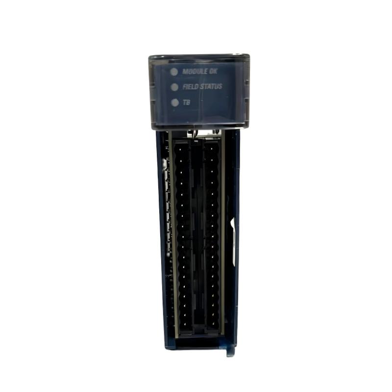
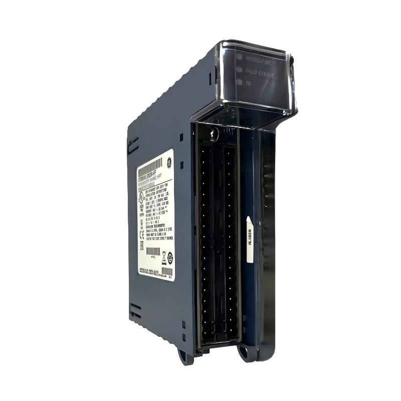
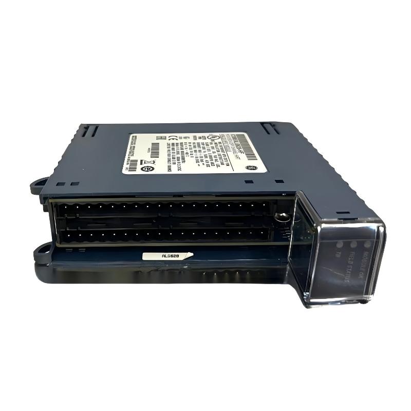
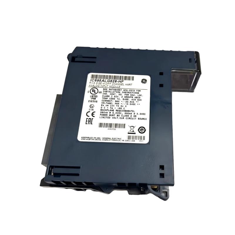
- GE
- IC695ALG628
- RX3i Analog Input Module
- USA
- 145 x 34 x 140 mm
- 0.45 kg
- Xiamen, China
- New & In Stock
- T/T, PayPal, Western Union
- 1 Year
- 1-3 Working Days
- DHL, UPS, TNT, FedEx and EMS.
- 24-Hour Service
- COO
- 46
Our advantage

Global Logistics
We have a 10-year logistics and express cooperation agreement, so our products can be shipped to any place in the world.

Brand new and original
Our products are imported in bulk from the place of origin. Because of the cooperative relationship, our products are all original and 100% new.

24-hour service
We provide 7*24 hours service to our customers. We will be there whenever you need us.

Price advantage
All our products are priced very favorably because we have our own warehouse and supply.
| Company Information | |||
| [email protected] | |||
| Mobile | +8615980777398 | ||
| +8615980777398 | |||
| 15980777398 |
Product Overview
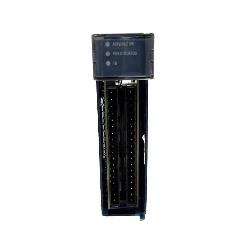
The GE IC695ALG628 is a high-performance RX3i Analog Input Module developed for the GE PACSystems RX3i programmable automation platform. The module is designed to acquire analog signals from industrial field devices and convert them into high-precision digital values for real-time monitoring, process control, and automation applications.
Installed in an RX3i Universal Backplane, the IC695ALG628 provides reliable analog data acquisition for process variables such as temperature, pressure, flow, level, position, and other continuous measurement signals. Its high-speed processing capability, excellent signal stability, and advanced diagnostic functions make it suitable for demanding industrial environments requiring accurate and dependable control.
Measuring 145 × 34 × 140 mm and weighing approximately 0.45 kg, the module features a compact mechanical design that simplifies cabinet installation while maximizing rack utilization. Designed for continuous industrial operation, it supports reliable communication with the RX3i CPU through the backplane bus and integrates seamlessly into distributed control and automation systems.
Product Identification
| Parameter | Specification |
|---|---|
| Manufacturer | GE |
| Product Series | PACSystems RX3i |
| Model | IC695ALG628 |
| Product Type | Analog Input Module |
| System Platform | RX3i PLC |
| Primary Function | Analog Signal Acquisition |
| Installation | RX3i Universal Backplane |
| Dimensions | 145 × 34 × 140 mm |
| Weight | 0.45 kg |
| Mounting Method | Rack Installation |
| Communication | RX3i Backplane Bus |
| Cooling | Natural Air Convection |
Technical Specifications
| Technical Item | Specification |
|---|---|
| Product Family | PACSystems RX3i |
| Module Category | Analog Input Module |
| Installation Platform | RX3i Universal Rack |
| Signal Type | Analog Input |
| Signal Conversion | Analog-to-Digital |
| Height | 145 mm |
| Width | 34 mm |
| Depth | 140 mm |
| Weight | Approximately 0.45 kg |
| Diagnostics | Channel and Module Diagnostics |
| Isolation | Industrial Grade |
| Operating Mode | Continuous Industrial Service |
Main Functions
The IC695ALG628 continuously monitors analog signals from field instruments and transfers processed digital values to the RX3i controller for automation tasks.
Typical connected devices include:
- Pressure transmitters
- Temperature transmitters
- Flow transmitters
- Level sensors
- Position transmitters
- Industrial analyzers
- Process monitoring instruments
- Environmental monitoring devices
Signal processing flow:
Field Device
↓
Analog Signal
↓
IC695ALG628
↓
RX3i Backplane
↓
RX3i CPU
↓
PLC Logic
↓
HMI / SCADA
↓
Industrial Process Control
Working Principle
Each analog channel receives an electrical signal generated by a field instrument.
The module performs the following sequence:
- Receive analog input from the field device.
- Filter electrical noise.
- Convert the analog signal into high-resolution digital data.
- Transfer data through the RX3i backplane.
- Process values within the RX3i CPU.
- Apply engineering scaling and calculations.
- Make process values available for monitoring, alarms, trending, and control.
This process allows the controller to make accurate real-time decisions based on continuously changing process conditions.
Typical Industrial Applications
The GE IC695ALG628 is widely deployed in:
- Power generation
- Oil & Gas
- Chemical processing
- Water and wastewater treatment
- Food and beverage production
- Pharmaceutical manufacturing
- Mining operations
- Steel production
- Pulp and paper mills
- Cement plants
- Marine automation
- Factory automation
Installation Guide
1. Verify Module Information
Confirm the installed module is:
GE IC695ALG628 RX3i Analog Input Module
Verify that the hardware configuration matches the engineering documentation.
2. Confirm System Compatibility
Ensure compatibility with:
- RX3i CPU
- RX3i Universal Backplane
- RX3i Power Supply
- Engineering software configuration
- Control cabinet design
3. Inspect the Module
Before installation inspect:
- Front housing
- Identification label
- Backplane connector
- Terminal interface
- Locking mechanism
- Overall mechanical condition
Replace the module if physical damage is detected.
4. Prepare Installation Space
Module dimensions:
- Height: 145 mm
- Width: 34 mm
- Depth: 140 mm
Allow sufficient clearance for:
- Air circulation
- Cable routing
- Future maintenance
- Module replacement
5. Remove System Power
Before installation:
- Stop the PLC.
- Disconnect control power.
- Verify power isolation.
- Follow lockout/tagout procedures.
6. Install the Module
Insert the module into the designated RX3i rack slot.
Verify:
- Correct alignment
- Fully seated connector
- Locked retaining mechanism
- Proper slot assignment
7. Connect Analog Field Wiring
Connect field devices according to approved wiring documentation.
Check:
- Terminal assignments
- Signal polarity
- Shield continuity
- Cable identification
- Channel mapping
Avoid routing analog signal cables alongside high-voltage power wiring.
8. Verify Grounding
Inspect:
- Cabinet protective earth
- Analog signal grounding
- Cable shield termination
- Ground continuity
Effective grounding minimizes electrical interference and improves measurement accuracy.
9. Configure the Module
Within the engineering software:
- Add the IC695ALG628 module.
- Configure analog input channels.
- Select measurement ranges.
- Configure engineering units.
- Enable diagnostic functions.
- Define alarm thresholds where required.
10. Start the System
Restore power and verify:
- Module LEDs
- CPU communication
- Channel status
- Analog values
- Diagnostic information
Commissioning Procedure
Step 1
Download the hardware configuration to the RX3i controller.
Step 2
Verify that the controller recognizes the module.
Step 3
Confirm communication through the backplane.
Step 4
Compare displayed analog values with calibrated field instruments.
Step 5
Verify scaling and alarm functions.
Step 6
Perform operational testing under normal process conditions.
Troubleshooting Guide
Fault 1 — Module Not Detected
Possible causes:
- Module not fully inserted
- Incorrect rack slot
- Hardware configuration mismatch
- Backplane communication issue
- Power supply fault
Fault 2 — No Analog Input
Possible causes:
- Open signal wiring
- Failed transmitter
- Incorrect channel configuration
- No transmitter power
- Loose terminal connection
Fault 3 — Incorrect Analog Reading
Possible causes:
- Wrong signal range
- Incorrect scaling
- Sensor calibration error
- Wiring polarity error
- Faulty transmitter
Fault 4 — Signal Noise
Possible causes:
- Poor grounding
- Damaged cable shield
- Electromagnetic interference
- Loose wiring
- High-power equipment nearby
Fault 5 — Multiple Channels Fail
Inspect:
- Power supply
- Backplane communication
- Common wiring
- Module diagnostics
- PLC hardware configuration
Fault 6 — Single Channel Failure
Check:
- Sensor
- Signal cable
- Terminal block
- Channel configuration
- Diagnostic status
Fault 7 — Communication Error
Possible causes:
- Backplane failure
- CPU communication issue
- Module seating problem
- Hardware fault
Fault 8 — HMI Displays Incorrect Value
Inspect:
- PLC scaling
- Engineering units
- Tag mapping
- HMI configuration
- PLC application program
Fault 9 — Intermittent Signal
Possible causes:
- Loose connector
- Vibration
- Moisture
- Cable damage
- Electrical interference
Fault 10 — Module Diagnostic Alarm
Possible causes:
- Internal module fault
- Configuration mismatch
- Field wiring problem
- Abnormal input signal
- Hardware failure
Review controller diagnostics before replacing the module.
Diagnostic Workflow
Follow this troubleshooting sequence:
Field Instrument
↓
Signal Wiring
↓
IC695ALG628
↓
RX3i Backplane
↓
RX3i CPU
↓
PLC Logic
↓
HMI / SCADA
↓
Controlled Equipment
This systematic approach minimizes downtime and prevents unnecessary hardware replacement.
Preventive Maintenance
Routine maintenance should include:
Mechanical Inspection
- Housing integrity
- Module retention
- Connector condition
- Rack installation
Electrical Inspection
- Terminal tightness
- Wiring insulation
- Ground continuity
- Shield condition
Software Inspection
- Hardware configuration
- Diagnostic logs
- Alarm history
- Firmware compatibility
Environmental Inspection
- Cabinet temperature
- Dust accumulation
- Humidity
- Airflow
- Cooling performance
Preventive Maintenance Checklist
| Inspection Item | Recommended Action |
|---|---|
| Module Housing | Visual inspection |
| Backplane Connector | Check condition |
| Wiring | Tighten terminals |
| Grounding | Verify continuity |
| Cable Shield | Inspect integrity |
| Diagnostics | Review alarms |
| PLC Program Backup | Archive regularly |
| Cabinet Ventilation | Clean and inspect |
Replacement Procedure
- Record module slot information.
- Back up the PLC project.
- Remove control power.
- Disconnect field wiring.
- Remove the existing module.
- Inspect the rack connector.
- Install the replacement IC695ALG628.
- Reconnect field wiring.
- Download hardware configuration.
- Restore power.
- Verify communication.
- Check analog input values.
- Confirm alarm operation.
- Return the system to service.
Key Advantages
- High-precision analog signal acquisition
- Reliable RX3i backplane communication
- Compact 34 mm module width
- Comprehensive diagnostic capabilities
- Stable long-term measurement accuracy
- Industrial-grade electrical isolation
- Easy installation and replacement
- Excellent resistance to industrial electrical noise
- Seamless integration with PACSystems RX3i
- Suitable for mission-critical industrial applications
Frequently Asked Questions
What is the GE IC695ALG628?
The GE IC695ALG628 is an RX3i Analog Input Module designed to acquire analog signals from industrial field instruments for use within GE PACSystems RX3i PLC systems.
What are its dimensions?
145 × 34 × 140 mm
What is its weight?
Approximately 0.45 kg.
Which platform supports this module?
It is designed for the GE PACSystems RX3i automation platform.
What types of devices can be connected?
Pressure transmitters, temperature transmitters, flow meters, level sensors, position transmitters, analyzers, and other industrial analog instruments.
Why are analog values unstable?
Common causes include poor grounding, damaged shielded cables, loose terminals, electrical interference, incorrect scaling, or transmitter faults.
Why isn’t the module recognized by the PLC?
Check module installation, rack compatibility, power supply, backplane communication, and hardware configuration.
What should be verified before replacing the module?
Inspect the field instruments, wiring, transmitter power supply, channel configuration, PLC diagnostics, and backplane status to confirm that the module is the actual source of the fault.
Conclusion
The GE IC695ALG628 RX3i Analog Input Module is a reliable analog signal acquisition solution for demanding industrial automation systems. With dimensions of 145 × 34 × 140 mm and a weight of 0.45 kg, it offers compact installation while delivering accurate and stable measurement performance for continuous process control.
Correct installation, proper grounding, accurate hardware configuration, and regular preventive maintenance are essential for maximizing module reliability. During troubleshooting, engineers should follow a structured diagnostic process—from field devices and wiring through the RX3i backplane, PLC, and HMI—to identify the root cause efficiently, reduce downtime, and ensure long-term system performance.