

ProductPRODUCT
Featured products
Contact Us
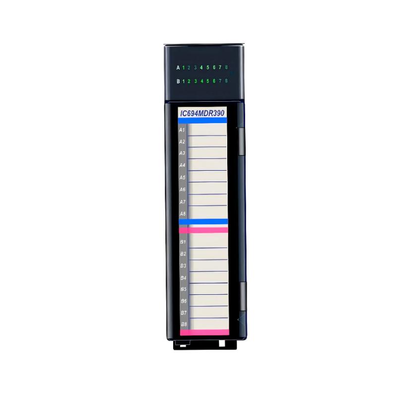
- GE
- IC694MDR390
- Hybrid I/O Module
- USA
- 145 x 34 x 140 mm
- 0.16 kg
- Xiamen, China
- New & In Stock
- T/T, PayPal, Western Union
- 1 Year
- 1-3 Working Days
- DHL, UPS, TNT, FedEx and EMS.
- 24-Hour Service
- COO
- 68
Our advantage

Global Logistics
We have a 10-year logistics and express cooperation agreement, so our products can be shipped to any place in the world.

Brand new and original
Our products are imported in bulk from the place of origin. Because of the cooperative relationship, our products are all original and 100% new.

24-hour service
We provide 7*24 hours service to our customers. We will be there whenever you need us.

Price advantage
All our products are priced very favorably because we have our own warehouse and supply.
| Company Information | |||
| [email protected] | |||
| Mobile | +8615980777398 | ||
| +8615980777398 | |||
| 15980777398 |
Product Overview
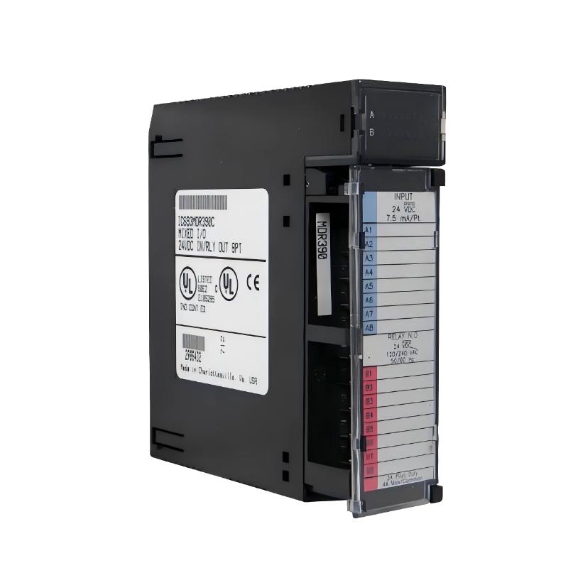
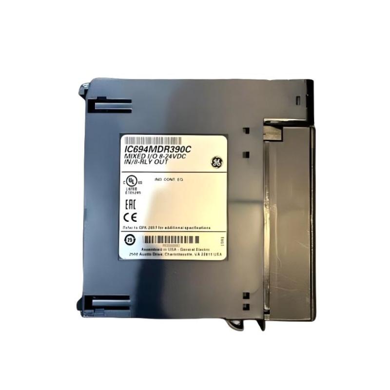
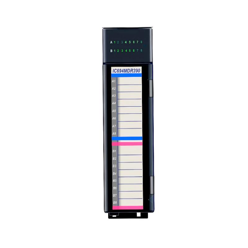
The GE IC694MDR390 Hybrid I/O Module is an industrial PLC I/O component designed to combine input and output functions within a single module. This type of mixed I/O architecture can be useful when a control panel requires both field signal monitoring and discrete device control without dedicating separate rack positions to every signal type.
In an automation system, the I/O module forms the interface between the PLC processor and physical equipment. Inputs allow the controller to monitor field conditions, while outputs allow the control program to command external devices.
The specified dimensions of the GE IC694MDR390 are 145 × 34 × 140 mm, with a specified weight of 0.16 kg.
Because the module directly interfaces with field wiring, correct electrical compatibility, terminal assignment, signal levels, load characteristics, grounding, and wiring practices are particularly important during installation and commissioning.
Product Identification
| Parameter | Specification |
|---|---|
| Manufacturer | GE |
| Series | IC694 |
| Model | IC694MDR390 |
| Product Type | Hybrid I/O Module |
| Main Function | Combined Input and Output Interface |
| Application | Industrial PLC Automation |
| Dimensions | 145 × 34 × 140 mm |
| Weight | 0.16 kg |
| Installation | PLC Rack |
| System Role | Field Signal Interface |
| Signal Category | Discrete I/O |
| Typical Applications | Machine Control, Equipment Monitoring, Sequencing |
Technical Specifications
| Technical Item | Specification |
|---|---|
| Manufacturer | GE |
| Model | IC694MDR390 |
| Product Category | Hybrid I/O Module |
| Main Function | Combined Digital Input / Output Interface |
| Dimensions | 145 × 34 × 140 mm |
| Weight | 0.16 kg |
| Installation Environment | Industrial Control Cabinet |
| System Role | PLC Field Interface |
| Application | Discrete Machine Control |
| Input Function | Field-State Monitoring |
| Output Function | Discrete Device Control |
| Maintenance | Wiring, Configuration, and Signal Inspection |
The exact input count, output count, voltage ranges, current ratings, isolation characteristics, switching behavior, terminal assignments, and load limitations should be verified against the applicable system documentation before wiring the module.
What Is the IC694MDR390 Used For?
The IC694MDR390 is designed for applications where a PLC needs both input and output functionality in the same rack position.
A simplified control path is:
Field Sensor
↓
IC694MDR390 Input
↓
PLC CPU
↓
Control Logic
↓
IC694MDR390 Output
↓
Actuator
This arrangement can reduce the number of individual modules required for certain machine-control applications.
Typical uses include:
- Machine sequencing
- Equipment monitoring
- Sensor monitoring
- Solenoid control
- Relay-interface applications
- Motor control signals
- Conveyor systems
- Packaging machinery
- General discrete automation
Hybrid I/O Architecture
A conventional PLC rack may use separate modules:
Input Module
Output Module
A hybrid module combines these functions into one hardware component.
This can be useful where a machine section has a relatively small number of inputs and outputs.
For example:
| Field Device | Function |
|---|---|
| Proximity Sensor | Input |
| Limit Switch | Input |
| Pushbutton | Input |
| Solenoid | Output |
| Indicator | Output |
| Relay Command | Output |
The exact electrical requirements must be checked before connecting field devices.
Installation Guide
1. Verify the Module
Confirm the module identification:
GE IC694MDR390
Inspect the module before installation.
Look for:
- Cracked housing
- Damaged terminals
- Bent connectors
- Corrosion
- Contamination
- Physical impact
- Signs of overheating
Do not install a visibly damaged module.
2. Confirm Rack Compatibility
Before installing the module, verify:
- PLC rack compatibility
- CPU compatibility
- Slot assignment
- Power arrangement
- I/O configuration
- Adjacent module compatibility
A hybrid I/O module must be installed within a compatible PLC architecture.
3. Check Dimensions
The specified dimensions are:
145 × 34 × 140 mm
Provide enough cabinet space for:
- Module installation
- Field wiring
- Terminal access
- Cable routing
- Ventilation
- Maintenance
Avoid obstructing nearby equipment.
4. Check Weight
The specified weight is:
0.16 kg
Although the module itself is lightweight, connected field wiring can introduce mechanical stress. Support heavier cables appropriately.
5. Isolate Power
Before installation or removal:
- Stop the machine safely.
- Shut down the PLC system.
- Isolate applicable electrical power.
- Apply lockout/tagout procedures.
- Verify the absence of hazardous voltage.
- Follow plant electrical-safety procedures.
6. Install the Module
Align the IC694MDR390 with the assigned rack position.
Insert the module carefully until it is fully seated.
Avoid:
- Excessive force
- Misalignment
- Twisting
- Connector impact
- Contamination
7. Secure the Module
Verify:
- Proper module seating
- Mechanical retention
- Connector engagement
- Correct alignment
- Adequate clearance
A loose module can cause intermittent I/O operation.
Field Wiring Preparation
Before connecting field devices, identify every I/O point.
Create a wiring schedule containing:
- Device name
- Input/output designation
- Signal voltage
- Field terminal
- PLC address
- Load information
- Cable identification
This is especially useful for hybrid modules because input and output circuits share the same physical module.
Input Wiring
Typical input devices can include:
- Pushbuttons
- Limit switches
- Proximity sensors
- Photoelectric sensors
- Pressure switches
- Level switches
Before wiring an input, verify:
- Sensor voltage
- Signal type
- Common/reference arrangement
- Input compatibility
- Polarity where applicable
Output Wiring
Possible output loads can include:
- Relays
- Contactors through suitable interfaces
- Solenoid valves
- Indicator devices
- Control circuits
Before connecting an output, verify:
- Load voltage
- Load current
- Switching characteristics
- Inductive-load requirements
- Protection requirements
Do not connect a load merely because its nominal voltage appears similar to the system voltage.
Inductive Loads
Inductive loads such as relays and solenoids can produce transient voltage when switched.
Depending on the circuit design, appropriate suppression may be required.
Possible protective methods can include suitable:
- Flyback suppression
- Surge suppression
- RC networks
- Interface relays
The correct method depends on the load and electrical architecture.
Wiring Separation
Separate I/O wiring from high-energy conductors where practical.
Avoid routing low-level signal wiring directly alongside:
- Motor power cables
- Variable-frequency drive output cables
- Welding circuits
- High-current power conductors
Good routing practices help reduce electrical interference.
Commissioning Procedure
Step 1 – Verify Wiring
Before applying power, check:
- Input wiring
- Output wiring
- Common connections
- Terminal tightness
- Cable identification
- Short circuits
- Incorrect cross-connections
Step 2 – Verify Configuration
Confirm that the PLC program and hardware configuration match the installed IC694MDR390.
Check:
- Slot assignment
- Input addresses
- Output addresses
- Control logic
- Interlocks
Step 3 – Power Up
Apply power according to the approved commissioning sequence.
Observe the PLC and module status.
Check for abnormal diagnostic indications.
Step 4 – Test Inputs
Activate each input individually.
For example:
Limit Switch OFF
→ PLC input OFF
Then:
Limit Switch ON
→ PLC input ON
Confirm that the PLC program receives the expected signal.
Step 5 – Test Outputs
Command each output individually during a controlled test.
Verify:
PLC Output Command
↓
IC694MDR390 Output
↓
Field Device
The field device should respond according to the intended control sequence.
Step 6 – Test Combined Operation
After individual I/O testing, operate the machine sequence.
Verify:
- Inputs change correctly
- Outputs respond correctly
- Interlocks operate
- Alarms function
- Machine sequencing is correct
Troubleshooting Guide
Fault 1 – Input Does Not Change State
Possible Causes
- Sensor failure
- Incorrect wiring
- Missing sensor power
- Incorrect signal voltage
- Loose terminal
- Configuration problem
- Input circuit fault
Diagnostic Procedure
Trace the signal:
Sensor → Wiring → IC694MDR390 Input → PLC
Fault 2 – Input Remains Permanently ON
Possible Causes
- Short circuit
- Incorrect wiring
- Sensor stuck ON
- Electrical interference
- Incorrect common connection
- Input circuit problem
Disconnect the field source only when safe and according to the maintenance procedure, then determine whether the input state changes.
Fault 3 – Output Does Not Activate
Possible Causes
- PLC logic does not command the output
- Incorrect output address
- Wiring problem
- Missing load power
- Load failure
- Output circuit problem
Trace:
PLC Logic → Output Address → IC694MDR390 → Field Wiring → Load
Fault 4 – Output Command Is Present but Load Does Not Operate
Possible causes include:
- Open field circuit
- Missing external power
- Damaged load
- Incorrect wiring
- Loose terminal
- Inadequate load interface
The presence of a PLC output command does not necessarily mean that the external load is receiving the expected electrical power.
Fault 5 – Output Remains ON
Possible Causes
- PLC program continuously commands output
- Incorrect interlock
- Wiring short
- Output circuit fault
- External circuit problem
First determine whether the PLC is actually commanding the output.
Fault 6 – Multiple Inputs Fail
If several inputs fail simultaneously, investigate common causes:
- Sensor power
- Common wiring
- Rack power
- Configuration
- Connector
- Module hardware
Multiple simultaneous failures are often more likely to involve shared infrastructure than independent sensor failures.
Fault 7 – Multiple Outputs Fail
Possible causes include:
- Common load power failure
- Wiring problem
- Configuration issue
- Module fault
- PLC program problem
Check whether the affected outputs share a common electrical path.
Fault 8 – Inputs Work but Outputs Do Not
This condition can help narrow the fault.
Investigate:
- Output configuration
- Output power
- Load wiring
- Load condition
- Output circuit
The CPU and input side may still be operating correctly.
Fault 9 – Outputs Work but Inputs Do Not
Investigate:
- Sensor power
- Input wiring
- Input common
- Sensor compatibility
- Input configuration
Fault 10 – Intermittent I/O Operation
Possible Causes
- Loose terminals
- Vibration
- Cable damage
- Electrical interference
- Poor grounding
- Temperature-related connection problems
Inspect both the module and the connected field wiring.
Fault Diagnosis Flow
Use the following sequence:
Field Device
↓
Field Wiring
↓
IC694MDR390
↓
PLC Rack
↓
CPU
↓
PLC Program
↓
Actuator
This helps determine whether the fault is in the field device, wiring, I/O module, rack, controller, or application logic.
Preventive Maintenance
Module Inspection
Inspect the IC694MDR390 for:
- Physical damage
- Connector condition
- Contamination
- Corrosion
- Heat discoloration
- Secure seating
Terminal Inspection
Check field terminals for:
- Loose connections
- Corrosion
- Damaged conductors
- Poor crimping
- Insulation damage
Loose terminals are a common source of intermittent I/O faults.
Sensor Maintenance
Periodically inspect connected sensors for:
- Mechanical damage
- Contamination
- Incorrect alignment
- Cable deterioration
- Unstable operation
Output Load Inspection
Check connected output devices for:
- Coil damage
- Overheating
- Mechanical sticking
- Excessive current
- Wiring problems
Cabinet Maintenance
Maintain:
- Clean air
- Appropriate temperature
- Adequate ventilation
- Low humidity
- Low vibration
Preventive Maintenance Table
| Maintenance Area | Recommended Action |
|---|---|
| Module Housing | Inspect for physical damage |
| Module Seating | Verify secure installation |
| Terminals | Check tightness and condition |
| Input Sensors | Check operation and alignment |
| Output Loads | Inspect electrical and mechanical condition |
| Wiring | Check insulation and routing |
| Cabinet | Keep clean and dry |
| Grounding | Verify according to system design |
| PLC Configuration | Confirm I/O assignments |
| Diagnostics | Review abnormal conditions |
Industrial Applications
Machine Automation
The IC694MDR390 can be used where a machine requires both sensor inputs and discrete outputs.
A typical sequence could be:
Part Detected
↓
PLC Processes Input
↓
Machine Sequence
↓
Solenoid Activated
Conveyor Systems
Hybrid I/O can be useful in conveyor sections containing both:
- Product-detection sensors
- Motor or actuator control signals
This can simplify the rack configuration for smaller machine zones.
Packaging Equipment
Packaging machines frequently contain numerous discrete signals.
Examples include:
- Product sensors
- Limit switches
- Door switches
- Solenoid valves
- Control relays
A combined I/O module can provide a compact interface for suitable applications.
Material Handling
Material-handling systems may require simultaneous monitoring and control of:
- Position sensors
- Proximity switches
- Pneumatic valves
- Conveyors
- Machine interlocks
Machine Sequencing
A hybrid I/O module can participate in sequences such as:
Sensor Detection
→
CPU Logic
→
Output Command
→
Actuator
→
Next Sensor Event
This creates a closed-loop discrete control sequence.
Hybrid I/O vs. Separate I/O Modules
| Feature | Hybrid I/O Module | Separate I/O Modules |
|---|---|---|
| Inputs and Outputs | Combined | Separate |
| Rack Space | Potentially Reduced | More Positions Required |
| Wiring | Mixed on One Module | Grouped by Function |
| Small Machine Sections | Suitable | May Be More Hardware Than Needed |
| Large Systems | Application Dependent | Easier Functional Separation |
| Maintenance | Mixed I/O Diagnostics | Function-Specific Modules |
A hybrid module is particularly attractive when the machine section has a modest combination of inputs and outputs.
System Integration
A typical PLC architecture is:
Field Sensors
↓
IC694MDR390
↔
PLC CPU
↓
IC694MDR390 Outputs
↓
Actuators
The CPU executes the control program while the hybrid I/O module provides the electrical interface to field equipment.
Replacement Procedure
1. Document Existing Wiring
Before removal, record:
- Module position
- Terminal assignments
- Input addresses
- Output addresses
- Connected devices
- Common connections
Photographs and wiring labels can help prevent reconnection errors.
2. Back Up PLC Configuration
Save:
- PLC program
- Hardware configuration
- I/O mapping
- Relevant machine parameters
3. Isolate Power
Stop the machine and isolate applicable electrical power.
Follow lockout/tagout requirements.
4. Disconnect Field Wiring
Label all field wires before removing them.
Keep input and output wiring clearly identified.
5. Remove the Existing Module
Release the module’s retaining mechanism and carefully remove it from the rack.
6. Inspect the Rack Connection
Check the rack connector for:
- Bent contacts
- Contamination
- Damage
- Corrosion
7. Install the Replacement
Install the replacement module in the correct position.
Verify complete seating.
8. Reconnect Wiring
Reconnect each conductor according to the documented terminal assignment.
Double-check every input and output before applying power.
9. Test Inputs and Outputs
Test each circuit individually.
Confirm:
- Input state
- Output command
- Field response
- PLC address
- Machine sequence
Replacement Considerations
| Parameter | Specification / Check |
|---|---|
| Manufacturer | GE |
| Model | IC694MDR390 |
| Product Type | Hybrid I/O Module |
| Dimensions | 145 × 34 × 140 mm |
| Weight | 0.16 kg |
| Rack Compatibility | Confirm |
| Input Configuration | Confirm |
| Output Configuration | Confirm |
| Voltage Requirements | Confirm |
| Current Ratings | Confirm |
| Terminal Assignment | Confirm |
| PLC Configuration | Confirm |
The correct replacement must match the electrical characteristics and system configuration, not merely the physical dimensions.
Key Advantages
- Combines input and output functionality
- Provides a compact PLC I/O solution
- Reduces the need for separate I/O modules in suitable applications
- Supports machine-control architectures
- Provides direct field-device interfacing
- Suitable for discrete automation
- Useful for equipment monitoring and control
- Compact module format
- Dimensions: 145 × 34 × 140 mm
- Weight: 0.16 kg
Technical FAQs
What is the GE IC694MDR390?
The GE IC694MDR390 is identified as a hybrid I/O module designed to combine input and output functions within a compatible PLC system.
What are the dimensions of the IC694MDR390?
The specified dimensions are 145 × 34 × 140 mm.
What is the weight of the IC694MDR390?
The specified weight is 0.16 kg.
What is a hybrid I/O module?
A hybrid I/O module combines input and output functions in one module, allowing the PLC to monitor field signals and control external devices using a shared module position.
What devices can be connected to the input side?
Depending on the supported electrical characteristics, applications can include switches, proximity sensors, photoelectric sensors, limit switches, and other discrete field devices.
What devices can be connected to the output side?
Suitable applications may include relays, solenoids, indicators, and other compatible discrete loads. Load voltage and current must be verified before connection.
Why does an input fail to change state?
Check the sensor, sensor power, wiring, terminal connection, signal compatibility, module configuration, and input circuit.
Why does an output command not operate the actuator?
Check PLC logic, output addressing, field power, wiring, load condition, and output-circuit compatibility.
Why do several inputs fail at the same time?
A shared sensor supply, common wiring, module connection, rack problem, or configuration issue may affect multiple inputs simultaneously.
Why do several outputs fail at the same time?
Check common output power, wiring, PLC logic, configuration, and module condition.
Why are hybrid I/O modules useful?
They can reduce rack-space requirements when a machine section needs a combination of inputs and outputs.
What should be checked before replacing the module?
Verify the module model, rack compatibility, I/O configuration, electrical characteristics, terminal assignments, field wiring, and PLC configuration.
Conclusion
The GE IC694MDR390 Hybrid I/O Module provides a compact interface between a compatible PLC system and discrete field devices. By combining input and output functions in one module, it can be useful for machine sections that require both monitoring and control while maintaining an efficient rack configuration.
The specified dimensions are 145 × 34 × 140 mm, and the specified weight is 0.16 kg.
Installation should begin with confirmation of rack compatibility and electrical requirements. Field wiring should then be carefully identified, separated where appropriate, and checked for correct voltage, polarity, common connections, and load characteristics. During commissioning, inputs and outputs should be tested individually before the complete machine sequence is operated.
For troubleshooting, the most effective method is to follow the actual signal path from field device → wiring → IC694MDR390 → PLC CPU → control logic → output circuit → actuator. This makes it easier to distinguish sensor faults, wiring problems, configuration errors, module faults, and field-load problems.
Regular inspection of the module, terminals, sensors, output devices, wiring, and cabinet environment can help maintain reliable I/O operation and reduce unexpected downtime in industrial automation systems.