

ProductPRODUCT
Featured products



Contact Us
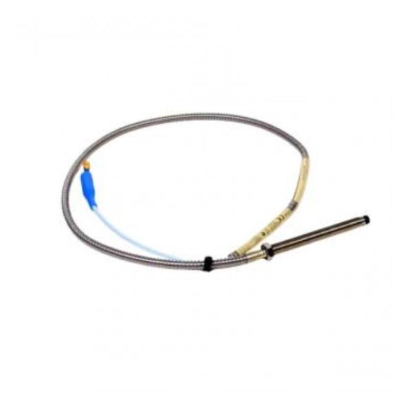
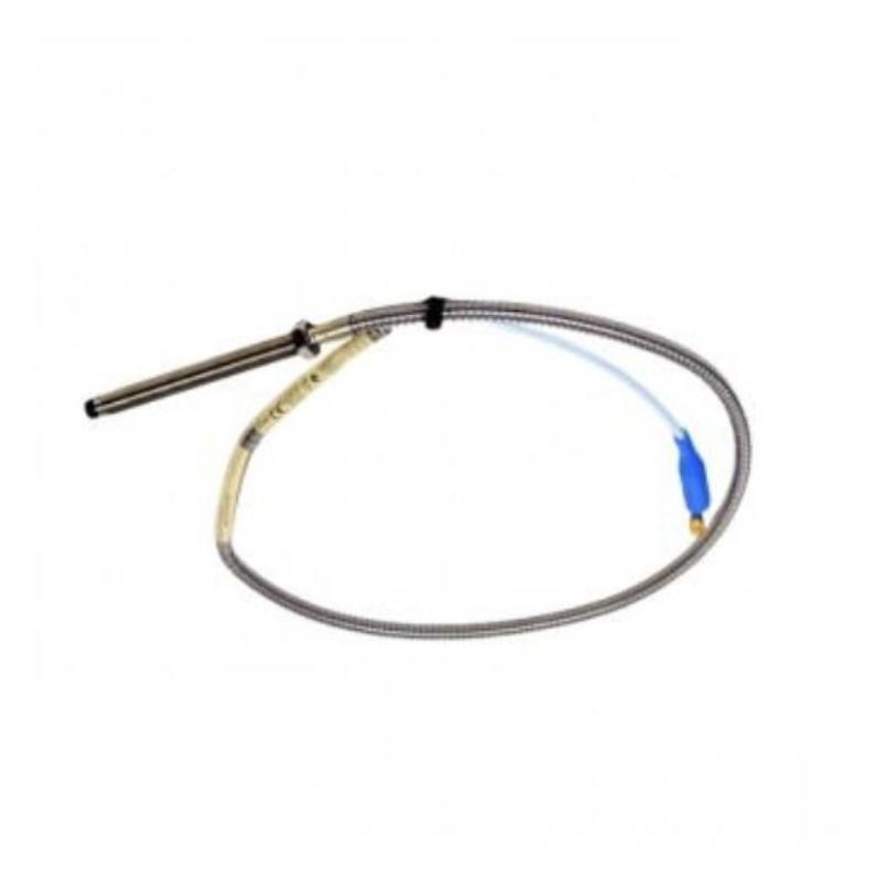
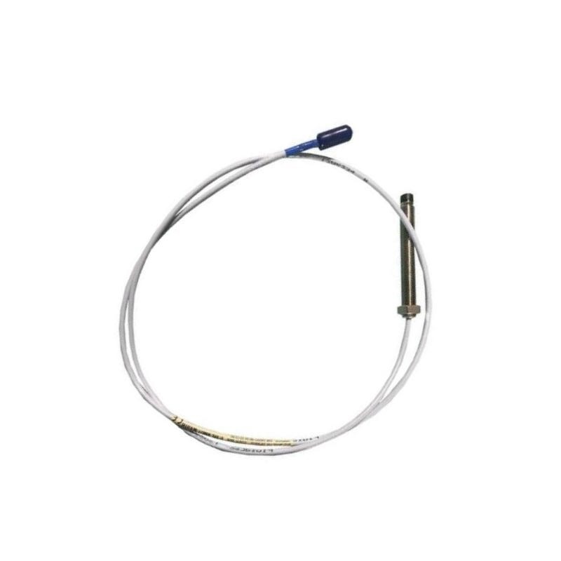
- Bently Nevada
- 330706-005-046-10-02-00
- 3300 XL 11mm Reverse Mount Probe
- USA
- 46 mm
- 0.07kg
- Xiamen, China
- New & In Stock
- T/T, PayPal, Western Union
- 1 Year
- 1-3 Working Days
- DHL, UPS, TNT, FedEx and EMS.
- 24-Hour Service
- COO
- 3
Our advantage

Global Logistics
We have a 10-year logistics and express cooperation agreement, so our products can be shipped to any place in the world.

Brand new and original
Our products are imported in bulk from the place of origin. Because of the cooperative relationship, our products are all original and 100% new.

24-hour service
We provide 7*24 hours service to our customers. We will be there whenever you need us.

Price advantage
All our products are priced very favorably because we have our own warehouse and supply.
| Company Information | |||
| [email protected] | |||
| Mobile | +8615980777398 | ||
| +8615980777398 | |||
| 15980777398 |
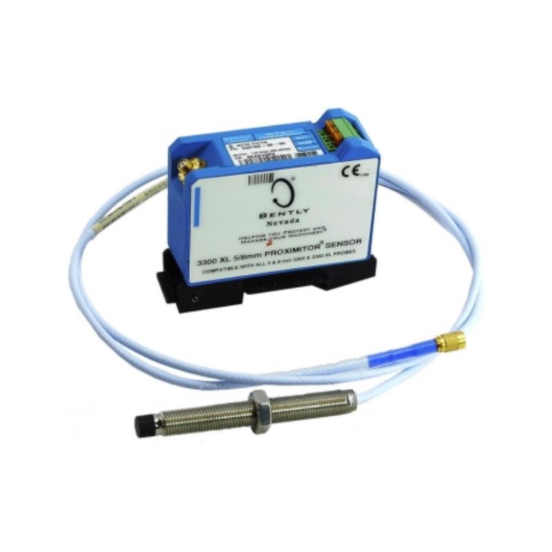
Bently Nevada 330706-005-046-10-02-00 — Product Description, Technical Parameters, Applications, and Related Models
1. Product Overview
The Bently Nevada 330706-005-046-10-02-00 is the specific part number covered in this product description. For industrial equipment procurement, maintenance, and spare-parts management, the complete model number should be retained when identifying the product and comparing it with existing equipment.
The exact product category, series designation, and technical configuration of this model cannot be confirmed from the part number alone. Accordingly, the description below distinguishes general industrial monitoring practices from specifications that require product-specific confirmation.
This distinction is important when a component is intended for installation in a machinery monitoring system. A similar-looking part number does not necessarily indicate identical electrical characteristics, mechanical dimensions, connection arrangements, or operating limits.
2. Basic Product Information
| Parameter | Product Information |
|---|---|
| Brand | Bently Nevada |
| Full model number | 330706-005-046-10-02-00 |
| Product series | Requires confirmation |
| Product category | Requires confirmation |
| Exact product function | Requires confirmation |
| Intended industry | Industrial machinery and equipment, subject to product identification |
| Typical system role | Depends on the confirmed component type |
| Measurement capability | Not confirmed |
| Electrical interface | Not confirmed |
| Mounting method | Not confirmed |
| Connector configuration | Not confirmed |
| Operating voltage | Not confirmed |
| Operating temperature | Not confirmed |
| Dimensions | Not confirmed, mm |
| Net weight | Not confirmed, kg |
| Shipping weight | Not confirmed, kg |
| Accessories | Depends on the actual product configuration |
| Compatibility | Must be checked against the installed equipment and technical documentation |
Bently Nevada 330706-005-046-10-02-00 — Product Description, Technical Specifications, Applications, Advantages, and Related Models
1. Product Overview
The Bently Nevada 330706-005-046-10-02-00 is a 3300 XL 11 mm reverse-mount proximity probe designed for non-contact displacement measurement in a compatible proximity transducer system.
The probe is intended to operate as part of a matched measurement chain. Depending on the application and system configuration, proximity probes can provide information about shaft movement, vibration, and relative displacement in rotating machinery. The probe works with compatible extension-cable and signal-conditioning components; selecting the correct combination is essential for accurate measurements.
The reverse-mount design is useful when the available mounting arrangement differs from a conventional front-mounted installation. The model’s ordering code identifies important configuration details, including the probe’s mounting arrangement, case length, total lead length, connector type, and approval option.
This model belongs to the 3300 XL 11 mm Proximity Transducer System product family. It is primarily relevant to industrial machinery monitoring, especially applications where non-contact shaft-position or vibration measurements are required.
2. Basic Product Information
| Parameter | Specification |
|---|---|
| Brand | Bently Nevada |
| Model | 330706-005-046-10-02-00 |
| Product series | 3300 XL 11 mm Proximity Transducer System |
| Product category | Reverse-mount proximity probe |
| Sensor technology | Non-contact proximity measurement |
| Nominal probe size | 11 mm series |
| Mounting configuration | Reverse mount |
| Thread specification | M10 × 1 |
| Fixed case length | 46 mm |
| Fixed unthreaded length | 5 mm |
| Total probe lead length | 1.0 m |
| Connector | Miniature ClickLoc coaxial connector |
| Cable construction | 75-ohm triaxial cable, FEP insulation |
| Probe tip material | Polyphenylene sulfide (PPS), subject to configuration verification |
| Probe case material | Stainless steel; exact grade should be verified for the ordered version |
| Agency approval option | 00 — no agency approval option selected |
| Measurement principle | Non-contact displacement sensing |
| Typical system use | Shaft vibration and relative-position monitoring, subject to system configuration |
| Overall probe length | 1.0 m lead length; complete physical envelope should be checked against the product drawing |
| Overall dimensions | Exact packaged and installed dimensions require confirmation |
| Net weight | Approximately 0.05–0.07 kg as an indicative product-weight range; confirm the actual supplied unit |
| Shipping weight | Depends on packaging and accessories; some listings specify approximately 2 kg |
| System compatibility | Requires a matched 3300 XL 11 mm probe, extension cable, and Proximitor Sensor configuration |
Weight clarification: The probe itself is a lightweight component, but shipping weight can be considerably higher because it may include protective packaging or additional items. For freight calculations, use the supplier’s confirmed packed weight rather than the estimated net weight.
3. Detailed Product Description
3.1 Reverse-Mount Probe Design
The 330706-005-046-10-02-00 is designed for reverse mounting, providing an alternative installation arrangement for machinery where the mounting space or access direction makes a conventional probe configuration unsuitable.
The M10 × 1 mounting thread and 46 mm fixed case length are important when checking the installation port, available clearance, and required probe position. These mechanical details should be compared with the actual machine drawing before the component is installed.
Correct positioning is particularly important in proximity measurement because the probe must be installed at the specified distance from the target surface. The target material, mounting geometry, and electrical characteristics of the complete measurement chain all affect the resulting signal.
3.2 Non-Contact Displacement Measurement
A proximity probe measures the distance between its sensing tip and a suitable conductive target without requiring direct mechanical contact. In rotating machinery applications, the target is commonly a shaft or another approved metallic surface.
When integrated with the appropriate signal-conditioning equipment, the measurement system can provide information about relative shaft displacement. This information may be used to assess vibration trends, shaft position, and other machine conditions supported by the installed monitoring configuration.
The probe should not be treated as a standalone monitoring instrument. Its output and measurement performance depend on the complete transducer system, including the probe, extension cable, signal conditioner, target characteristics, and monitoring channel.
3.3 Configuration and Connection
This model specifies a 1.0 m total probe lead and a miniature ClickLoc coaxial connector. The connector arrangement should be checked against the installed cable and signal-conditioning hardware before ordering a replacement.
The complete ordering code should be retained in purchasing records. Substituting a probe with a different lead length, connector, mounting configuration, or electrical characteristic may affect compatibility with the existing installation.
4. Technical Specifications
The table below consolidates the principal mechanical and configuration details.
| Technical Parameter | Specification |
|---|---|
| Model | 330706-005-046-10-02-00 |
| Brand | Bently Nevada |
| Series | 3300 XL 11 mm |
| Probe type | Reverse-mount proximity probe |
| Sensing method | Non-contact |
| Nominal probe family | 11 mm |
| Mounting thread | M10 × 1 |
| Mounting arrangement | Reverse mount |
| Fixed case length | 46 mm |
| Fixed unthreaded section | 5 mm |
| Total lead length | 1.0 m |
| Connector style | Miniature ClickLoc coaxial |
| Cable impedance | 75 ohms |
| Cable insulation | FEP |
| Cable construction | Triaxial |
| Probe tip material | PPS, subject to confirmation of the supplied version |
| Probe case | Stainless steel |
| Operating temperature | Confirm the applicable probe datasheet before use |
| Measurement range | Depends on the complete transducer system and approved application |
| Sensitivity | Confirm against the applicable system specification |
| Output characteristics | Determined by the matched probe and signal-conditioning system |
| Overall installed dimensions | Confirm from the mechanical drawing |
| Net weight | Approximately 0.05–0.07 kg, indicative only |
| Shipping weight | Packaging-dependent; confirm with the supplier |
| Approval option | 00 — no agency approval option selected |
| Required accessories | Compatible extension cable and Proximitor Sensor, as specified for the installation |
4.1 Dimensions and Weight
For engineering purposes, the probe’s lead length should not be confused with the dimensions of the entire packaged product. The 1.0 m value refers to the specified total probe lead length; the mounting case, connector, and packaging have their own physical dimensions.
| Physical Parameter | Value |
|---|---|
| Total probe lead length | 1,000 mm |
| Fixed case length | 46 mm |
| Fixed unthreaded length | 5 mm |
| Mounting thread | M10 × 1 |
| Probe body diameter | Confirm from the applicable mechanical drawing |
| Probe tip dimensions | Confirm from the applicable mechanical drawing |
| Connector dimensions | Confirm from the connector drawing |
| Complete installed envelope | Confirm from the mechanical drawing |
| Net product weight | Approximately 0.05–0.07 kg, indicative |
| Packaging dimensions | Not confirmed |
| Shipping weight | Not confirmed; packaging-dependent |
The fixed case length, unthreaded length, and total lead length serve different purposes and should be recorded separately. This is especially important when replacing a probe in an existing machine housing.
5. Product Applications
5.1 Steam and Gas Turbines
In suitable turbine installations, proximity probes can be used to monitor relative shaft movement and support the assessment of machine operating conditions. The resulting measurements can help maintenance teams identify changes that require investigation.
The probe must be installed in a suitable measurement position and connected to a compatible monitoring channel. The specific measurement—such as shaft vibration or axial position—depends on the mechanical arrangement and the configuration of the complete monitoring system.
5.2 Centrifugal and Process Compressors
Compressors may operate continuously under changing loads and process conditions. Where an approved proximity measurement system is installed, shaft displacement measurements can help maintenance teams evaluate changes in machine behavior.
Correct probe positioning, target geometry, and system configuration are essential. A probe selected for a replacement project should match the installed measurement chain rather than being chosen solely because its model number looks similar.
5.3 Pumps and Other Rotating Equipment
Industrial pumps, motors, and other rotating machinery may use non-contact measurement systems where shaft displacement information is required. These installations can form part of a broader condition-monitoring program.
The applicability of this particular 11 mm reverse-mount probe should be determined by the machine design and monitoring-system requirements. It should not be assumed to be suitable for every pump or motor.
5.4 Machinery Protection and Condition Monitoring
A compatible proximity transducer system can provide measurements to a machinery monitor for trend analysis, alarm evaluation, and equipment protection functions supported by the installed hardware.
The probe itself does not independently perform all monitoring or protection functions. Reliable operation requires correct installation, suitable signal conditioning, appropriate monitoring configuration, and verification of the measurement channel.
5.5 Maintenance and Replacement Projects
During equipment overhauls, maintenance teams may replace probes that have been damaged or require service. Using the complete model number helps ensure that the new component has the required mounting geometry, lead length, connector, and approval configuration.
The installation should be followed by the prescribed electrical and functional checks before the equipment is returned to service.
6. Product Advantages
6.1 Reverse-Mount Configuration
The reverse-mount design provides an alternative mechanical arrangement for applications where mounting access or available space is limited. This can be useful when the machine housing and probe installation point have been designed around a reverse-mounted component.
The practical benefit depends on the actual installation geometry. Clearance, thread engagement, target position, and service access should all be evaluated before replacement.
6.2 Non-Contact Sensing
Non-contact measurement avoids direct mechanical contact between the sensing tip and the target surface during normal operation. This makes proximity measurement suitable for certain rotating-shaft applications where continuous relative-displacement information is required.
Measurement performance still depends on the target material, correct gap setting, cable characteristics, and the compatible signal-conditioning equipment.
6.3 Defined Mechanical Configuration
The specified M10 × 1 thread, 46 mm fixed case length, and 5 mm fixed unthreaded section provide important reference points for mechanical planning.
These values help maintenance teams compare the proposed component with the existing installation and determine whether the mounting arrangement is suitable.
6.4 Standardized Lead and Connector Arrangement
The specified 1.0 m lead and miniature ClickLoc coaxial connector make it possible to identify the intended connection configuration during procurement and maintenance.
Maintaining the same documented configuration helps reduce the risk of mismatched cables or connectors. The complete measurement chain should still be checked before installation.
6.5 Integration into an Established Monitoring System
When correctly matched with the appropriate extension cable, Proximitor Sensor, and monitoring hardware, the probe can contribute to a continuous machinery-monitoring installation.
This can support trend analysis, maintenance planning, and investigation of abnormal machine behavior. The exact available functions depend on the installed monitoring system and its configuration.
6.6 Support for Planned Maintenance
A clearly identified replacement component helps maintenance teams plan work, maintain spare-parts records, and document equipment changes. Recording the full part number and installation location also makes future troubleshooting more straightforward.
7. Installation and Maintenance Considerations
Before Installation
-
Confirm the complete part number: 330706-005-046-10-02-00.
-
Verify that the machine is designed for the 3300 XL 11 mm probe family.
-
Check the M10 × 1 mounting thread and the available installation clearance.
-
Confirm the required 46 mm case length and 5 mm unthreaded section.
-
Verify that the 1.0 m lead and connector arrangement match the existing system.
-
Check the extension cable and Proximitor Sensor configuration.
-
Confirm the applicable environmental limits and installation instructions.
During Installation
The probe should be handled carefully to avoid damaging the sensing tip, cable, or connector. The mounting procedure and tightening requirements should follow the documentation for the exact probe configuration.
The probe-to-target gap must be established according to the applicable installation procedure. Incorrect gap settings or an unsuitable target surface can affect measurement accuracy and may result in an unreliable signal.
After Installation
Before returning the equipment to service, verify the connections, configured monitoring channel, and measured signal according to the approved commissioning procedure. Where required, compare the measured values with the established baseline and confirm that alarm settings remain appropriate.
Routine Maintenance
Maintenance records should include the model number, machine location, installation date, inspection results, and replacement history. Any change to the probe, cable, signal conditioner, or monitor configuration should be documented.
8. Five Related Model Candidates
The following models are provided as candidates for technical comparison. They should not be regarded as confirmed drop-in replacements for the target probe. The first model is the target itself for reference; the remaining entries require verification of their exact ordering codes and configurations.
| Model | Brand | Series or Category | Available Parameter Information | Dimensions | Weight |
|---|---|---|---|---|---|
| 330706-005-046-10-02-00 | Bently Nevada | 3300 XL 11 mm reverse-mount probe | M10 × 1 thread; 46 mm case; 5 mm unthreaded section; 1.0 m lead; miniature ClickLoc connector | 1.0 m lead; case dimensions as specified above | Approx. 0.05–0.07 kg, indicative |
| 330706-005-046-10-02-00, alternate approval configuration | Bently Nevada | 3300 XL 11 mm | Confirm whether a different approval option is available for the required installation | Requires confirmation, mm | Requires confirmation, kg |
| 330706 series, alternate lead configuration | Bently Nevada | 3300 XL 11 mm | Compare lead length and electrical configuration with the installed system | Requires confirmation, mm | Requires confirmation, kg |
| 330706 series, alternate connector configuration | Bently Nevada | 3300 XL 11 mm | Compare connector and cable-protection options | Requires confirmation, mm | Requires confirmation, kg |
| 330706 series, alternate mounting configuration | Bently Nevada | 3300 XL 11 mm | Confirm mounting geometry and mechanical compatibility | Requires confirmation, mm | Requires confirmation, kg |
The final four entries are configuration categories rather than verified complete ordering codes. They are included to highlight the principal differences to check when sourcing a related probe. A purchasing order should use an exact, verified part number.
9. Five Additional Bently Nevada Models for Comparison
The models below represent other commonly encountered equipment categories within the broader machinery-monitoring product range. Their functions differ, so they should be treated as general product-family comparison candidates rather than direct substitutes for the 330706 reverse-mount probe.
| Model | Product Category | Main Technical Parameters | Dimensions | Weight |
|---|---|---|---|---|
| 330101-00-30-10-02-00 | 3300 XL 8 mm proximity probe family | Exact configuration, lead length, and connector must be verified from the complete part number | Requires confirmation, mm | Requires confirmation, kg |
| 330103-00-05-10-02-00 | 3300 XL 8 mm proximity probe family | Verify probe configuration, mounting arrangement, and connection options | Requires confirmation, mm | Requires confirmation, kg |
| 330180-50-00 | Proximity transducer system component; exact variant to be confirmed | Confirm the specific product type and electrical characteristics before comparison | Requires confirmation, mm | Requires confirmation, kg |
| 3500/42M | Machinery-monitoring module family | Module functions and supported channels depend on the exact hardware and configuration | Depends on module and rack arrangement; verify in mm | Requires confirmation, kg |
| 3500/22M | Machinery-monitoring interface module family | Interface functions and system compatibility depend on the installed configuration | Depends on module and rack arrangement; verify in mm | Requires confirmation, kg |
These models do not all perform the same function as a proximity probe. In particular, monitoring modules and interface modules are different types of equipment and should not be substituted for a probe. Their inclusion is intended to support broader product identification and maintenance planning.
10. How to Choose a Suitable Related Model
When evaluating a replacement or an alternative product, compare the following characteristics in order of importance:
| Comparison Item | What to Check |
|---|---|
| Probe family | Confirm whether the existing system requires an 11 mm probe or another specified probe family |
| Mounting arrangement | Verify reverse mount versus the required installation geometry |
| Thread | Confirm M10 × 1 or the exact thread required by the machine |
| Case length | Check the 46 mm fixed case length and available clearance |
| Lead length | Confirm that the total lead length matches the installation |
| Connector | Verify the miniature ClickLoc coaxial connection or the specified alternative |
| Cable and electrical characteristics | Match the required impedance, cable construction, and system configuration |
| Signal-conditioning component | Confirm compatibility with the installed Proximitor Sensor |
| Monitoring system | Check the channel configuration and system requirements |
| Dimensions and weight | Use confirmed drawings and product data, not estimated shipping measurements |
A similar model number or shared product-family designation is not sufficient to establish interchangeability. Final selection should be based on the complete ordering code and the requirements of the installed system.
11. Product Summary
The Bently Nevada 330706-005-046-10-02-00 is a 3300 XL 11 mm reverse-mount proximity probe intended for non-contact displacement measurement as part of a compatible transducer system.
Its key identifying features include the reverse-mount configuration, M10 × 1 mounting thread, 46 mm fixed case length, 5 mm fixed unthreaded section, 1.0 m total lead length, and miniature ClickLoc coaxial connector.
The principal advantages are its defined mechanical configuration, non-contact measurement method, and suitability for integration into an appropriately configured machinery-monitoring system. Potential applications include shaft vibration and relative-position monitoring on suitable rotating machinery.
For purchasing and installation, the most important step is to verify the complete probe configuration, connection arrangement, and compatibility with the installed cable, signal conditioner, and monitoring hardware. Dimensions and weight should be confirmed from the actual product drawing and packing information before being used for engineering approval or freight calculations.