

ProductPRODUCT
Featured products



Contact Us
- GE
- IC694CPU771
- CPU Module
- USA
- 130 × 90 × 40 mm
- 0.3 kg
- Xiamen, China
- New & In Stock
- T/T, PayPal, Western Union
- 1 Year
- 1-3 Working Days
- DHL, UPS, TNT, FedEx and EMS.
- 24-Hour Service
- COO
- 77
Our advantage

Global Logistics
We have a 10-year logistics and express cooperation agreement, so our products can be shipped to any place in the world.

Brand new and original
Our products are imported in bulk from the place of origin. Because of the cooperative relationship, our products are all original and 100% new.

24-hour service
We provide 7*24 hours service to our customers. We will be there whenever you need us.

Price advantage
All our products are priced very favorably because we have our own warehouse and supply.
| Company Information | |||
| [email protected] | |||
| Mobile | +8615980777398 | ||
| +8615980777398 | |||
| 15980777398 |
Product Overview
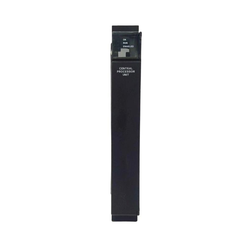
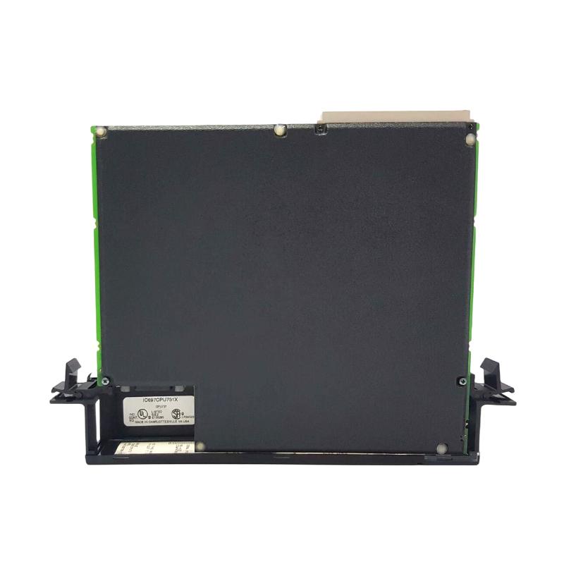
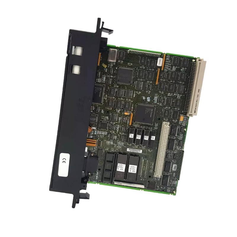
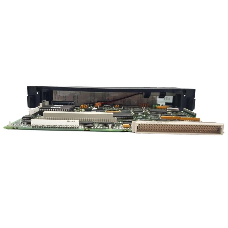
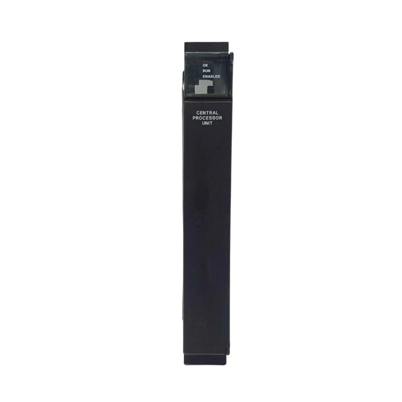
The GE IC694CPU771 CPU Module is the central processing component of a compatible GE industrial PLC control system. As the controller’s processing unit, the CPU module coordinates the execution of the control program, processes input information, manages output commands, and exchanges data with other modules and connected automation equipment.
In a typical PLC architecture, the CPU acts as the decision-making center. Field signals are collected through input modules, processed according to the programmed control strategy, and then translated into commands for output modules, drives, actuators, and other system devices.
The specified dimensions of the GE IC694CPU771 are 130 × 90 × 40 mm, with a specified weight of 0.3 kg.
Because the CPU is central to PLC operation, installation quality, configuration accuracy, stable power, rack compatibility, and program integrity are all important factors when commissioning or troubleshooting the module.
Product Identification
| Parameter | Specification |
|---|---|
| Manufacturer | GE |
| Series | IC694 |
| Model | IC694CPU771 |
| Product Type | CPU Module |
| Main Function | PLC Program Execution and System Control |
| Application | Industrial Automation |
| Dimensions | 130 × 90 × 40 mm |
| Weight | 0.3 kg |
| Installation | PLC Rack / Control Cabinet |
| System Role | Central Processing Unit |
| Typical Functions | Logic Processing, I/O Management, System Coordination |
| Maintenance | Diagnostic, Configuration, and Hardware Inspection |
Technical Specifications
| Technical Item | Specification |
|---|---|
| Manufacturer | GE |
| Model | IC694CPU771 |
| Product Category | CPU Module |
| Primary Function | PLC Processing |
| Dimensions | 130 × 90 × 40 mm |
| Weight | 0.3 kg |
| Installation Environment | Industrial Control Cabinet |
| System Role | Central Controller |
| Application | PLC-Based Automation |
| Program Function | Control Logic Execution |
| I/O Management | Coordinates Connected I/O |
| Maintenance | Program, Configuration, and Hardware Diagnostics |
The exact processor performance, memory capacity, communication interfaces, supported programming features, firmware compatibility, scan characteristics, and system limitations should be verified against the specific PLC configuration before commissioning.
What Is the GE IC694CPU771?
The IC694CPU771 is a CPU module that performs the central processing function of a compatible PLC system.
A simplified architecture can be represented as:
Sensors
↓
Input Modules
↓
IC694CPU771
↓
Control Logic
↓
Output Modules
↓
Actuators
The CPU receives information from the control system, executes the programmed logic, and determines the appropriate control response.
It may also coordinate communication and data exchange with other system components depending on the overall PLC architecture.
Main Functions of the CPU Module
Program Execution
The CPU executes the PLC control program cyclically or according to the applicable processing architecture.
The program can include:
- Logic operations
- Timers
- Counters
- Interlocks
- Sequencing
- Alarm handling
- Data processing
- Equipment control
I/O Processing
The CPU processes information received from input modules and generates commands for output modules.
For example:
Proximity Sensor
→
Digital Input Module
→
IC694CPU771
→
Control Logic
→
Digital Output Module
→
Solenoid Valve
System Coordination
The CPU provides the central processing point for the PLC system.
Depending on the system configuration, it can coordinate:
- Local I/O
- Expansion racks
- Communication modules
- Specialty modules
- Machine sequencing
- Diagnostic information
Installation Guide
1. Verify the CPU Model
Before installation, confirm:
GE IC694CPU771
Check the identification label carefully.
Do not substitute a similar-looking CPU without verifying processor, rack, firmware, configuration, and system compatibility.
2. Inspect the CPU
Before installation, inspect the module for:
- Cracked housing
- Bent connectors
- Damaged mounting components
- Corrosion
- Contamination
- Physical impact
- Abnormal connector condition
A damaged CPU should not be installed into an operating control system.
3. Confirm Rack Compatibility
Before mounting the IC694CPU771, verify:
- PLC rack compatibility
- CPU position
- Power supply compatibility
- I/O architecture
- Expansion arrangement
- Communication architecture
- Installed module compatibility
The CPU is not an independent component; it must operate within a compatible PLC system.
4. Check Physical Dimensions
The specified dimensions are:
130 × 90 × 40 mm
Allow adequate cabinet clearance for:
- Module insertion
- Wiring
- Connectors
- Ventilation
- Diagnostic access
- Maintenance
Do not obstruct ventilation openings or place heat-generating equipment unnecessarily close to the CPU.
5. Consider Module Weight
The specified weight is:
0.3 kg
Although the CPU itself is relatively lightweight, the complete PLC rack may contain multiple modules and wiring.
Ensure the rack and cabinet structure are mechanically secure.
6. Shut Down and Isolate Power
Before installing or removing the CPU:
- Stop the machine safely.
- Shut down the PLC system.
- Isolate applicable electrical power.
- Apply lockout/tagout procedures.
- Verify that hazardous voltage is absent.
- Address stored energy.
- Follow plant electrical-safety procedures.
Removing or inserting a CPU in an energized system should only be performed if the specific system architecture explicitly supports such an operation.
7. Install the CPU
Align the IC694CPU771 with the appropriate rack position.
Insert it carefully until it is fully seated.
Avoid:
- Excessive insertion force
- Misalignment
- Twisting
- Impact
- Contamination of connectors
8. Secure the Module
After installation, verify:
- Proper seating
- Mechanical retention
- Connector engagement
- Module alignment
- Clearance from adjacent components
A poorly seated CPU can produce symptoms ranging from startup failure to intermittent system faults.
Power and Grounding Considerations
The CPU depends on a stable PLC power architecture.
Before commissioning, verify:
- Correct power supply
- Stable control voltage
- Proper grounding
- Appropriate protective devices
- Secure power connections
Power instability can cause:
- CPU resets
- Program interruptions
- Communication failures
- I/O faults
- Unexpected machine stops
Program and Configuration Preparation
Before commissioning a replacement or newly installed CPU, ensure that the correct control program and system configuration are available.
Maintain backups of:
- PLC program
- Hardware configuration
- I/O assignments
- Communication settings
- Device parameters
- System documentation
A CPU replacement without the correct program or configuration can leave the hardware operational but the machine non-functional.
Commissioning Procedure
Step 1 – Hardware Inspection
Confirm:
- IC694CPU771 correctly installed
- Rack secure
- Power supply connected
- I/O modules installed
- Communication connections secure
- No damaged wiring
Step 2 – Apply Power
Restore power according to the approved startup procedure.
Observe the CPU’s diagnostic indicators and system status.
Check for:
- Normal startup
- Fault indications
- Configuration errors
- Communication problems
Step 3 – Verify CPU Status
Confirm that the CPU reaches the expected operating state.
If a fault is displayed, record the diagnostic information before making changes.
Step 4 – Load or Verify the Control Program
If required, transfer the correct application program to the CPU.
Verify:
- Program version
- Hardware configuration
- I/O assignments
- Communication configuration
- Retentive data requirements
Do not assume that a replacement CPU automatically contains the correct application program.
Step 5 – Verify I/O
Test representative input and output points.
For example:
Input
Sensor ON
↓
PLC input changes state
↓
CPU processes logic
↓
Output command generated
↓
Actuator responds
Verify that the physical equipment behaves as expected.
Step 6 – Verify Communication
If the PLC system includes communication modules or networked devices, confirm:
- Device detection
- Data exchange
- Network status
- Communication diagnostics
A CPU can appear healthy while a communication configuration remains incorrect.
Step 7 – Test Machine Sequences
Run the machine through controlled operating sequences.
Verify:
- Start conditions
- Interlocks
- Stop functions
- Alarms
- Automatic sequences
- Manual controls
- Safety-related interfaces
Safety functions should always be verified according to the machine’s dedicated safety design and procedures.
Troubleshooting Guide
Fault 1 – CPU Does Not Start
Possible Causes
- No control power
- Incorrect power supply
- CPU not seated correctly
- Rack problem
- Configuration issue
- Hardware fault
Diagnostic Procedure
Check the system in this order:
Power Supply → Rack → CPU Seating → Configuration → CPU Diagnostics
Fault 2 – CPU Shows a Fault Condition
Possible causes include:
- Program error
- Configuration mismatch
- Hardware incompatibility
- Module fault
- Communication problem
- Memory or firmware-related issue
Record the diagnostic information before resetting the controller.
Repeatedly clearing the fault without identifying the cause can make diagnosis more difficult.
Fault 3 – PLC Program Does Not Execute
Possible Causes
- CPU is not in the required operating mode
- Program not loaded
- Configuration error
- CPU fault
- I/O configuration problem
- Program integrity issue
Check the CPU operating status and program availability.
Fault 4 – CPU Repeatedly Resets
Possible Causes
- Unstable power
- Loose power connection
- Electrical interference
- Hardware problem
- Excessive environmental conditions
- Configuration issue
Monitor control power during the reset event if appropriate.
Fault 5 – I/O Modules Are Not Responding
Possible Causes
- CPU configuration mismatch
- Rack connection issue
- I/O module fault
- Communication problem
- Power supply issue
- Incorrect I/O mapping
Determine whether one module or the entire I/O system is affected.
If multiple modules fail simultaneously, investigate common infrastructure first.
Fault 6 – One I/O Module Is Missing
If only one module is affected, inspect:
- Module seating
- Slot assignment
- Configuration
- Module status
- Field wiring
- Module hardware
The CPU should not immediately be assumed to be defective.
Fault 7 – Communication Devices Are Offline
Possible Causes
- Communication configuration error
- Network cable problem
- Communication module problem
- Addressing issue
- Network power loss
- CPU configuration problem
Check whether the problem affects one device or the entire network.
Fault 8 – Machine Stops Unexpectedly
Possible Causes
- CPU fault
- I/O signal loss
- Communication interruption
- Power instability
- Program interlock
- Field device fault
Review the PLC diagnostic status and machine sequence rather than replacing the CPU immediately.
Fault 9 – PLC Operates Intermittently
Possible Causes
- Loose module connection
- Power instability
- Electrical interference
- Temperature problem
- Vibration
- Communication instability
Intermittent problems require observation over time.
Inspect both the CPU and the surrounding rack infrastructure.
Fault 10 – Program Is Lost After Power Interruption
Possible causes may include:
- Incorrect memory configuration
- Program backup issue
- Power-related problem
- Battery or retention-related issue where applicable
- CPU memory problem
Maintain a verified program backup so that the controller can be restored efficiently.
Fault Diagnosis Flow
A practical troubleshooting sequence is:
Control Power
↓
PLC Rack
↓
IC694CPU771
↓
CPU Operating Status
↓
PLC Program
↓
I/O Modules
↓
Communication Network
↓
Field Devices
This approach prevents technicians from treating every PLC fault as a CPU hardware failure.
Preventive Maintenance
CPU Inspection
Inspect the IC694CPU771 for:
- Physical damage
- Connector condition
- Secure seating
- Diagnostic indications
- Contamination
- Corrosion
Power Supply Inspection
Check:
- Input power stability
- Output voltage
- Terminal tightness
- Grounding
- Protective devices
Power quality should be considered whenever unexplained CPU resets occur.
Cabinet Environment
Maintain suitable:
- Temperature
- Humidity
- Ventilation
- Cleanliness
- Vibration levels
Dust accumulation can restrict ventilation and contribute to thermal problems.
Program Backup
Keep current backups of:
- PLC program
- Hardware configuration
- Communication settings
- I/O mapping
- Machine parameters
A current backup is particularly important before performing CPU replacement or major system maintenance.
Configuration Records
Document:
- CPU model
- Rack arrangement
- Module positions
- Firmware information where applicable
- Network settings
- I/O assignments
- Program revision
This documentation reduces recovery time after hardware faults.
Preventive Maintenance Table
| Maintenance Area | Recommended Action |
|---|---|
| CPU Housing | Inspect for physical damage |
| Rack Connection | Verify secure seating |
| Power Supply | Check stability |
| Connectors | Inspect for contamination or damage |
| Cabinet | Keep clean and dry |
| Ventilation | Maintain adequate airflow |
| Program | Maintain current backup |
| Configuration | Keep hardware records updated |
| Communication | Review diagnostic status |
| I/O | Verify representative operation |
| Environment | Monitor temperature and vibration |
Industrial Applications
Machine Control
The CPU can serve as the central controller for automated machinery involving:
- Sensors
- Actuators
- Motors
- Valves
- Conveyors
- Interlocks
Manufacturing Lines
A central PLC CPU can coordinate multiple production stages.
For example:
Material Detection
↓
Processing
↓
Inspection
↓
Transfer
↓
Packaging
The CPU executes the programmed sequence and coordinates connected I/O.
Material Handling
Applications can include:
- Conveyor control
- Product detection
- Sorting
- Position monitoring
- Motor control
The CPU processes sensor information and determines appropriate machine actions.
Process Control
PLC-based process systems may use the CPU to coordinate:
- Pump control
- Valve operation
- Level monitoring
- Temperature control
- Alarm handling
The actual application depends on the installed I/O and control program.
Communication-Based Automation
When combined with compatible communication hardware, the CPU can participate in systems involving:
- Remote I/O
- Operator interfaces
- Drives
- Controllers
- Industrial networks
The communication functions depend on the specific system architecture.
CPU Module vs. I/O Module
| Feature | IC694CPU771 | I/O Module |
|---|---|---|
| Primary Function | PLC Processing | Field Signal Interface |
| Executes Control Logic | Yes | No |
| Processes Program | Yes | No |
| Controls System Sequence | Yes | Through CPU |
| Reads Field Inputs | Through I/O System | Direct Signal Interface |
| Controls Outputs | Through I/O System | Direct Output Interface |
| Central System Role | Yes | No |
The CPU and I/O modules therefore perform complementary functions.
CPU Replacement Procedure
1. Back Up the Existing System
Before replacement, save:
- PLC program
- Hardware configuration
- Network configuration
- Machine parameters
- Relevant diagnostic information
2. Record Existing Hardware
Document:
- CPU model
- Rack location
- Installed modules
- Communication connections
- Configuration information
3. Shut Down the System
Place the machine into a safe state.
Isolate applicable electrical power according to the maintenance procedure.
4. Remove the Existing CPU
Disconnect the required connections and remove the CPU carefully from the rack.
Avoid damaging the rack connector.
5. Inspect the Rack
Before installing the replacement, inspect:
- Rack connector
- Mounting area
- Adjacent modules
- Wiring
- Contamination
- Mechanical damage
6. Install the Replacement IC694CPU771
Install the replacement CPU carefully.
Ensure it is fully seated and mechanically secured.
7. Restore Configuration
Load or verify:
- PLC program
- Hardware configuration
- Communication settings
- I/O assignments
8. Test the System
Verify:
- CPU startup
- Operating status
- I/O communication
- Network communication
- Machine sequence
- Alarms
- Interlocks
Replacement Considerations
| Parameter | Specification / Check |
|---|---|
| Manufacturer | GE |
| Model | IC694CPU771 |
| Product Type | CPU Module |
| Dimensions | 130 × 90 × 40 mm |
| Weight | 0.3 kg |
| Rack Compatibility | Confirm |
| CPU Compatibility | Confirm |
| Program Compatibility | Confirm |
| Firmware Compatibility | Confirm |
| I/O Configuration | Confirm |
| Communication Configuration | Confirm |
| Power Requirements | Confirm |
A replacement CPU should not be selected based solely on dimensions or product-family similarity.
Key Advantages
- Provides central PLC processing
- Executes programmed control logic
- Coordinates compatible I/O modules
- Supports structured industrial automation architectures
- Acts as the central control point of the PLC system
- Suitable for machine and process-control applications
- Can coordinate local and expanded control-system hardware
- Compact CPU module format
- Dimensions: 130 × 90 × 40 mm
- Weight: 0.3 kg
- Supports centralized management of automation sequences
Technical FAQs
What is the GE IC694CPU771?
The GE IC694CPU771 is identified as a CPU module used as the central processing component of a compatible GE PLC control system.
What are the dimensions of the IC694CPU771?
The specified dimensions are 130 × 90 × 40 mm.
What is the weight of the IC694CPU771?
The specified weight is 0.3 kg.
What is the primary function of a PLC CPU?
The CPU executes the control program, processes system information, coordinates I/O, and manages the programmed machine-control sequence.
Can the IC694CPU771 operate without I/O modules?
The CPU is the processing component, but a practical automation system normally requires compatible I/O or communication hardware to interact with field equipment.
Why does a PLC CPU need a stable power supply?
Voltage instability can cause resets, communication problems, program interruptions, and unpredictable controller behavior.
Why might a CPU show a fault after replacing an I/O module?
Possible causes include incorrect configuration, incompatible hardware, improper module seating, or a problem with the I/O module or rack connection.
Why would multiple I/O modules stop working at the same time?
Common causes include CPU faults, rack problems, power issues, configuration errors, or communication failures.
What should be backed up before replacing the CPU?
Maintain backups of the PLC program, hardware configuration, I/O assignments, communication settings, and relevant machine parameters.
Can a CPU replacement restore a machine automatically?
Not necessarily. The replacement CPU may require the correct application program, hardware configuration, communication settings, and commissioning checks before the machine can return to normal operation.
What should be checked if the CPU repeatedly resets?
Investigate power stability, rack connections, environmental conditions, electrical interference, configuration, and hardware condition.
Why is documentation important when replacing a CPU?
Accurate documentation allows technicians to reproduce the previous system configuration and significantly reduces commissioning and recovery time.
Conclusion
The GE IC694CPU771 CPU Module serves as the central processing element of a compatible PLC automation system. With specified dimensions of 130 × 90 × 40 mm and a weight of 0.3 kg, the module provides the processing foundation around which I/O, communication, and field-control functions can be organized.
Reliable operation begins with correct rack compatibility, secure installation, stable power, appropriate configuration, and a verified PLC program. During commissioning, technicians should confirm CPU status, program execution, I/O response, communication, and machine sequencing rather than relying only on a successful power-up.
When troubleshooting, the most effective approach is to work systematically from power supply → rack → CPU → program → I/O → communication → field equipment. This prevents unnecessary CPU replacement and helps identify whether the actual problem originates in hardware, configuration, power, communication, or field wiring.
For maintenance and replacement work, maintaining current PLC programs, hardware configurations, I/O documentation, and communication records is essential for minimizing downtime and restoring the control system efficiently.