

ProductPRODUCT
Featured products



Contact Us
- GE
- IC694CHS392
- 10-Slot Expansion Base
- USA
- 443 x 130 x 142 mm
- 0.921 kg
- Xiamen, China
- New & In Stock
- T/T, PayPal, Western Union
- 1 Year
- 1-3 Working Days
- DHL, UPS, TNT, FedEx and EMS.
- 24-Hour Service
- COO
- 48
Our advantage

Global Logistics
We have a 10-year logistics and express cooperation agreement, so our products can be shipped to any place in the world.

Brand new and original
Our products are imported in bulk from the place of origin. Because of the cooperative relationship, our products are all original and 100% new.

24-hour service
We provide 7*24 hours service to our customers. We will be there whenever you need us.

Price advantage
All our products are priced very favorably because we have our own warehouse and supply.
| Company Information | |||
| [email protected] | |||
| Mobile | +8615980777398 | ||
| +8615980777398 | |||
| 15980777398 |
Product Overview
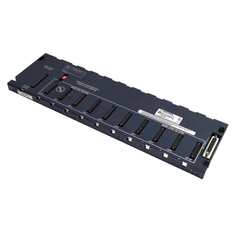
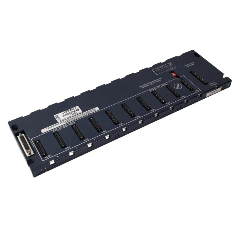
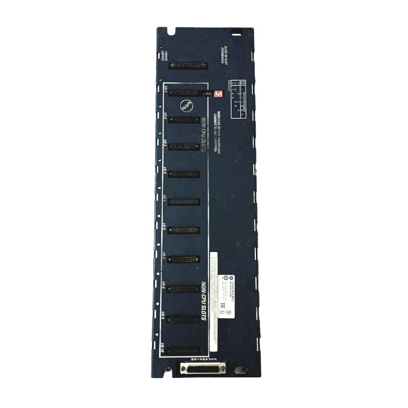
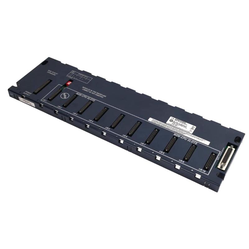
The GE IC694CHS392 10-Slot Expansion Base is a rack infrastructure component used to expand the available module positions within a compatible GE industrial automation control system. Unlike an active PLC CPU, I/O module, or communication module, the expansion base provides the physical and electrical infrastructure required for additional control-system modules.
Expansion bases are particularly useful when the primary PLC rack does not provide enough positions for the required combination of processors, I/O modules, communication modules, specialty modules, or future system expansion.
The specified dimensions of the GE IC694CHS392 are 443 × 130 × 142 mm, with a specified weight of 0.921 kg.
A correctly installed expansion base provides secure module mounting, organized rack construction, and a structured foundation for extending the PLC system.
Product Identification
| Parameter | Specification |
|---|---|
| Manufacturer | GE |
| Series | IC694 |
| Model | IC694CHS392 |
| Product Type | 10-Slot Expansion Base |
| Main Function | PLC Rack Expansion |
| Number of Slots | 10 |
| Application | Industrial Automation |
| Dimensions | 443 × 130 × 142 mm |
| Weight | 0.921 kg |
| Installation | Control Cabinet / PLC Rack |
| System Role | Module Mounting and Rack Expansion |
| Maintenance | Mechanical, Power, and Rack Inspection |
Technical Specifications
| Technical Item | Specification |
|---|---|
| Manufacturer | GE |
| Model | IC694CHS392 |
| Product Category | Expansion Base |
| Slot Capacity | 10 Slots |
| Main Function | Expansion of PLC Module Positions |
| Dimensions | 443 × 130 × 142 mm |
| Weight | 0.921 kg |
| Installation Environment | Industrial Control Cabinet |
| Application | PLC / Distributed Control System |
| Mounting Role | Module Support and Rack Infrastructure |
| Electrical Role | Rack / Backplane Infrastructure |
| Maintenance | Mechanical and Electrical Inspection |
The exact supported CPU, expansion architecture, interconnection method, power arrangement, module compatibility, and maximum system configuration should be verified for the specific PLC installation before commissioning.
What Is the IC694CHS392?
The IC694CHS392 is a 10-slot expansion base intended to provide additional module positions in a compatible industrial automation system.
A simplified PLC architecture can be represented as:
Main PLC Rack
↓
Expansion Connection
↓
IC694CHS392 Expansion Base
↓
Additional PLC Modules
The expansion base therefore extends the physical organization of the control system without requiring every module to be installed in the primary rack.
Why Use a 10-Slot Expansion Base?
A PLC installation may begin with only a few modules:
CPU + Power Supply + I/O
As the machine grows, additional functions may be required:
- Digital inputs
- Digital outputs
- Analog inputs
- Analog outputs
- Communication
- Motion-related functions
- High-speed counting
- Specialty control
Instead of replacing the entire rack architecture, an expansion base can provide additional module positions.
A larger system can therefore be organized as:
Main Rack
↓
Expansion Base
↓
Multiple Additional Modules
This can provide a more flexible and maintainable control architecture.
Installation Guide
1. Confirm the Expansion Base
Before installation, verify the identification:
GE IC694CHS392
Confirm that the component is the intended 10-slot expansion base.
Inspect the housing for:
- Cracks
- Deformation
- Damaged mounting points
- Damaged connectors
- Corrosion
- Contamination
- Signs of impact
2. Confirm System Compatibility
Before mounting the base, verify:
- PLC platform
- Rack architecture
- Expansion capability
- CPU compatibility
- Supported modules
- Expansion connections
- Power requirements
The physical appearance of an expansion base should not be used as the only basis for determining compatibility.
3. Check Physical Dimensions
The specified dimensions are:
443 × 130 × 142 mm
The control cabinet should provide adequate space for:
- Rack mounting
- Module insertion
- Wiring
- Cable routing
- Ventilation
- Maintenance access
Allow sufficient working space around the rack for technicians.
4. Consider the Weight
The specified weight is:
0.921 kg
The cabinet mounting structure must be able to safely support the expansion base together with the installed modules and connected wiring.
The final loaded rack may be significantly heavier than the empty base.
5. Plan the Rack Location
Choose a location that provides:
- Adequate mechanical support
- Easy module access
- Appropriate cable routing
- Sufficient ventilation
- Protection from excessive vibration
- Protection from moisture
- Suitable maintenance clearance
Avoid placing the expansion base in an area exposed to unnecessary mechanical shock.
6. Isolate Power Before Installation
Before installing or modifying the rack:
- Put the machine into a safe state.
- Shut down the control system.
- Isolate applicable electrical power.
- Apply lockout/tagout procedures.
- Verify the absence of hazardous voltage.
- Address stored energy.
- Follow site-specific electrical safety requirements.
7. Mount the Expansion Base
Position the IC694CHS392 carefully against the cabinet mounting surface.
Verify:
- Horizontal or vertical orientation as specified by the system design
- Mounting-hole alignment
- Mechanical support
- Adequate clearance
- No interference with nearby components
Secure the base using the appropriate mounting hardware.
Do not overtighten mounting hardware to the point of damaging the housing.
8. Inspect the Mounting
After securing the base, check that:
- The rack does not move excessively.
- Mounting hardware is secure.
- The base is properly aligned.
- There is no mechanical deformation.
- Module positions remain accessible.
9. Install the Modules
Install compatible modules into the expansion base according to the planned rack configuration.
Potential module categories can include:
- Digital I/O
- Analog I/O
- Communication modules
- Specialty modules
- High-speed modules
- Bus-related modules
The exact module combination must comply with the applicable system architecture.
10. Verify Module Seating
Every installed module should be fully seated and mechanically secured.
Check:
- Module alignment
- Connector engagement
- Retention mechanism
- Adjacent module clearance
A poorly seated module can create intermittent system faults.
Expansion Connection
The expansion base must be connected to the main PLC architecture using the appropriate system interconnection method.
Before making the connection, verify:
- Correct expansion cable or connection
- Correct connector
- Cable orientation
- Mechanical engagement
- Cable routing
- Connector condition
Do not force expansion connectors into position.
Wiring Considerations
Although the expansion base primarily provides rack infrastructure, installed modules will introduce field wiring into the rack.
Plan wiring so that:
- Signal cables are organized
- Power cables are separated where required
- Communication cables are protected
- Cable weight does not stress connectors
- Maintenance access remains available
Good cable organization becomes increasingly important as the rack approaches its full 10-slot capacity.
Commissioning Procedure
Step 1 – Mechanical Inspection
Before powering the system, confirm:
- Expansion base is securely mounted
- Modules are properly seated
- Expansion connection is secure
- Wiring is organized
- No foreign objects are present
Step 2 – Verify Rack Configuration
Compare the actual module arrangement with the engineering documentation.
Check:
- Slot assignments
- Module types
- Expansion arrangement
- Controller configuration
- I/O mapping
Step 3 – Power Up
Restore system power according to the approved commissioning procedure.
Observe:
- CPU status
- Module status
- Expansion status
- Diagnostic indicators
Step 4 – Confirm Module Recognition
The PLC system should recognize the expected modules according to the configured architecture.
Check for:
- Missing modules
- Unexpected module errors
- Configuration mismatches
- Rack faults
Step 5 – Test I/O
For each installed I/O module:
- Activate a known field input.
- Verify the corresponding PLC input.
- Command an output where appropriate.
- Verify the physical device response.
This confirms that the expansion rack is communicating correctly with the control system.
Step 6 – Test Under Operating Conditions
Operate the machine normally and monitor:
- Rack stability
- Module status
- Communication
- I/O operation
- Temperature
- Intermittent faults
A rack problem may not appear during a short startup test but become apparent after vibration, temperature changes, or sustained operation.
Troubleshooting Guide
Fault 1 – Expansion Base Is Not Recognized
Possible Causes
- Incorrect expansion connection
- Cable problem
- Configuration error
- CPU incompatibility
- Poor connector engagement
- Power issue
- Module configuration problem
Diagnostic Procedure
Check:
Main Rack → Expansion Connection → IC694CHS392 → Installed Modules
Fault 2 – All Expansion Modules Are Offline
If every module on the expansion base is unavailable, investigate common infrastructure first.
Possible causes include:
- Expansion connection failure
- Rack power issue
- Configuration problem
- CPU communication problem
- Base connection problem
Do not immediately replace all individual I/O modules.
Fault 3 – Only One Module Is Not Working
If most modules operate normally, investigate the individual module.
Check:
- Module seating
- Module configuration
- Connector
- Wiring
- Module status
- Field device
This helps distinguish a module-level problem from a rack-level problem.
Fault 4 – Intermittent Expansion Rack Fault
Possible Causes
- Loose connector
- Vibration
- Damaged expansion cable
- Poor mounting
- Temperature-related connection problem
- Module seating issue
Inspect all mechanical and electrical connections.
Fault 5 – PLC Reports Configuration Error
Possible Causes
- Incorrect module type
- Wrong slot assignment
- Unsupported module
- Configuration mismatch
- Incorrect expansion architecture
Compare the installed hardware with the engineering configuration.
Fault 6 – Module Works in Main Rack but Not in Expansion Base
Possible causes include:
- Expansion compatibility problem
- Incorrect rack position
- Expansion connection problem
- Configuration issue
- Power limitations
- Hardware fault
The fact that the module works elsewhere does not automatically prove that the expansion base is defective.
Fault 7 – Rack Resets During Machine Operation
Possible Causes
- Power instability
- Loose rack connection
- Mechanical vibration
- Poor electrical connection
- Overloaded power arrangement
- Environmental problem
Monitor the rack during the event and inspect common connections.
Fault 8 – Some Modules Lose Power
Possible Causes
- Power-distribution problem
- Loose connection
- Incorrect wiring
- Power supply problem
- Damaged rack connection
Check whether the affected modules share a common power path.
Fault 9 – Physical Module Does Not Fit
Possible Causes
- Incorrect module type
- Damaged guide
- Foreign object
- Mechanical deformation
- Incorrect installation orientation
Never force a module into the expansion base.
Fault 10 – Excessive Rack Movement
Possible Causes
- Loose mounting hardware
- Cabinet vibration
- Insufficient support
- Incorrect installation
Inspect the mounting structure and cabinet frame.
Fault Diagnosis Flow
A practical diagnostic sequence is:
PLC CPU
↓
Main Rack
↓
Expansion Connection
↓
IC694CHS392
↓
Individual Module
↓
Field Wiring
↓
Field Device
This approach helps identify whether the problem is located in the controller, expansion connection, base, module, wiring, or field equipment.
Preventive Maintenance
Rack Inspection
Inspect the IC694CHS392 for:
- Housing damage
- Mounting stability
- Corrosion
- Dust
- Moisture
- Connector condition
Module Inspection
Check installed modules for:
- Proper seating
- Mechanical retention
- Diagnostic indicators
- Connector condition
- Wiring integrity
Expansion Connection Inspection
Inspect the connection between the main rack and expansion base.
Check for:
- Loose connectors
- Cable damage
- Excessive bending
- Contamination
- Mechanical strain
Cabinet Environmental Inspection
Maintain:
- Clean air
- Appropriate ventilation
- Low contamination
- Controlled humidity
- Suitable temperature
- Low vibration
Preventive Maintenance Table
| Maintenance Area | Recommended Action |
|---|---|
| Expansion Base | Inspect housing |
| Mounting | Check mechanical security |
| Modules | Verify proper seating |
| Expansion Connection | Inspect connector and cable |
| Wiring | Check for damage and strain |
| Cabinet | Keep clean and dry |
| Ventilation | Maintain adequate airflow |
| Vibration | Monitor for excessive movement |
| Diagnostics | Review rack and module faults |
| Documentation | Keep rack configuration current |
Industrial Applications
Large Machine Control
Large machines often require more I/O than a single rack can conveniently accommodate.
A 10-slot expansion base can provide additional module positions for:
- Sensors
- Actuators
- Analog instruments
- Communication
- Specialty functions
Manufacturing Lines
Production lines may have several control zones.
An expanded PLC architecture can organize I/O according to machine sections while maintaining centralized control.
Material Handling
Conveyor and material-handling systems can require numerous I/O points distributed across the machine.
Expansion racks can provide additional capacity for:
- Photoelectric sensors
- Proximity sensors
- Motors
- Solenoids
- Position switches
Process Equipment
Industrial process systems may require a combination of:
- Analog inputs
- Analog outputs
- Digital signals
- Communication modules
- Specialty modules
An expansion base can provide the physical space needed for a larger module configuration.
Future System Expansion
A major advantage of providing additional rack capacity is future scalability.
A system can initially use:
CPU + Several I/O Modules
while retaining expansion capacity for:
Additional I/O + Communication + Specialty Modules
This can reduce the need for major cabinet redesign when the machine is upgraded.
Rack Layout Planning
A 10-slot expansion base should be planned as part of the complete cabinet architecture.
Consider:
- Module heat generation
- Wiring space
- Power distribution
- Communication routing
- Maintenance access
- Future expansion
- Cabinet dimensions
Do not simply fill every available position without considering the complete thermal and wiring design.
Replacement Procedure
1. Document the Rack
Before removing the expansion base, record:
- Rack position
- Installed modules
- Slot assignments
- Expansion connections
- Wiring
- Configuration
2. Shut Down the System
Place the machine in a safe state and isolate power according to the plant maintenance procedure.
3. Remove Installed Modules
Remove modules carefully according to their individual maintenance procedures.
Label wiring where necessary.
4. Disconnect the Expansion Connection
Disconnect the appropriate expansion connection.
Protect the connector from contamination and mechanical damage.
5. Remove the Base
Remove mounting hardware and carefully remove the IC694CHS392.
6. Install the Replacement
Position the replacement expansion base.
Check:
- Alignment
- Mounting
- Clearance
- Mechanical support
Secure the base.
7. Reinstall Modules
Return the modules to their documented positions.
Ensure each module is fully seated.
8. Reconnect the Expansion System
Reconnect the expansion connection and verify mechanical engagement.
9. Restore Power and Test
Verify:
- Rack recognition
- Module recognition
- I/O operation
- Communication
- Machine functionality
Replacement Considerations
| Parameter | Specification / Check |
|---|---|
| Manufacturer | GE |
| Model | IC694CHS392 |
| Product Type | 10-Slot Expansion Base |
| Slot Capacity | 10 |
| Dimensions | 443 × 130 × 142 mm |
| Weight | 0.921 kg |
| Rack Compatibility | Confirm |
| Expansion Architecture | Confirm |
| Module Compatibility | Confirm |
| Mounting Arrangement | Confirm |
| Connection Method | Confirm |
| Cabinet Clearance | Confirm |
The dimensions and slot count are important identification characteristics, but system compatibility must also be verified.
Key Advantages
- Provides 10 module positions
- Expands compatible PLC rack capacity
- Supports larger automation systems
- Provides structured module mounting
- Facilitates system expansion
- Helps organize I/O and specialty modules
- Suitable for industrial control cabinets
- Supports distributed or expanded rack architectures
- Dimensions: 443 × 130 × 142 mm
- Weight: 0.921 kg
- Useful for future PLC system expansion
Technical FAQs
What is the GE IC694CHS392?
The GE IC694CHS392 is identified as a 10-slot expansion base used to provide additional module positions within a compatible industrial automation system.
How many slots does the IC694CHS392 provide?
The specified configuration provides 10 module slots.
What are the dimensions of the IC694CHS392?
The specified dimensions are 443 × 130 × 142 mm.
What is the weight of the IC694CHS392?
The specified weight is 0.921 kg.
Does the IC694CHS392 function as a PLC CPU?
No. It is an expansion-base component that provides rack infrastructure and additional module positions.
Why use an expansion base?
An expansion base allows a control system to accommodate additional modules when the primary rack does not provide sufficient capacity.
Can any PLC module be installed in the IC694CHS392?
No. Module compatibility must be confirmed according to the applicable PLC architecture and rack configuration.
What should be checked if the expansion base is not recognized?
Check the expansion connection, rack power, controller configuration, module compatibility, connectors, and physical seating.
Why would all modules on an expansion base stop operating?
A common expansion connection, rack power, configuration, or infrastructure problem can affect multiple modules simultaneously.
What should be checked if only one module fails?
Inspect the individual module’s seating, configuration, wiring, connector, and field device before investigating the entire expansion base.
Can vibration cause expansion rack faults?
Yes. Excessive vibration can contribute to loose mounting, connector movement, and intermittent electrical connections.
How should the expansion base be maintained?
Inspect its mechanical mounting, connectors, environmental condition, expansion connection, and installed modules during scheduled maintenance.
Conclusion
The GE IC694CHS392 10-Slot Expansion Base provides the physical and system infrastructure required to expand a compatible industrial automation rack. With 10 available module positions, it is suited to control systems that require additional I/O, communication, specialty, or other compatible modules beyond the capacity of the primary rack.
The specified dimensions are 443 × 130 × 142 mm, and the specified weight is 0.921 kg. Because the expansion base supports multiple modules, cabinet planning should account not only for its physical dimensions but also for the combined weight, heat, wiring, and maintenance requirements of the completed rack.
Reliable operation depends on correct rack compatibility, secure mounting, proper expansion connections, accurate system configuration, and good cabinet maintenance. When troubleshooting, a useful approach is to start with common infrastructure—PLC CPU, main rack, expansion connection, and expansion base—before investigating individual modules.
When properly installed and maintained, the IC694CHS392 can provide a structured foundation for expanding PLC capacity and supporting larger industrial automation systems.