

ProductPRODUCT
Featured products



Contact Us
- GE
- IC694ACC311
- Terminal Block
- USA
- 134 x 90 x 35 mm
- 0.8 kg
- Xiamen, China
- New & In Stock
- T/T, PayPal, Western Union
- 1 Year
- 1-3 Working Days
- DHL, UPS, TNT, FedEx and EMS.
- 24-Hour Service
- COO
- 57
Our advantage

Global Logistics
We have a 10-year logistics and express cooperation agreement, so our products can be shipped to any place in the world.

Brand new and original
Our products are imported in bulk from the place of origin. Because of the cooperative relationship, our products are all original and 100% new.

24-hour service
We provide 7*24 hours service to our customers. We will be there whenever you need us.

Price advantage
All our products are priced very favorably because we have our own warehouse and supply.
| Company Information | |||
| [email protected] | |||
| Mobile | +8615980777398 | ||
| +8615980777398 | |||
| 15980777398 |
Product Overview
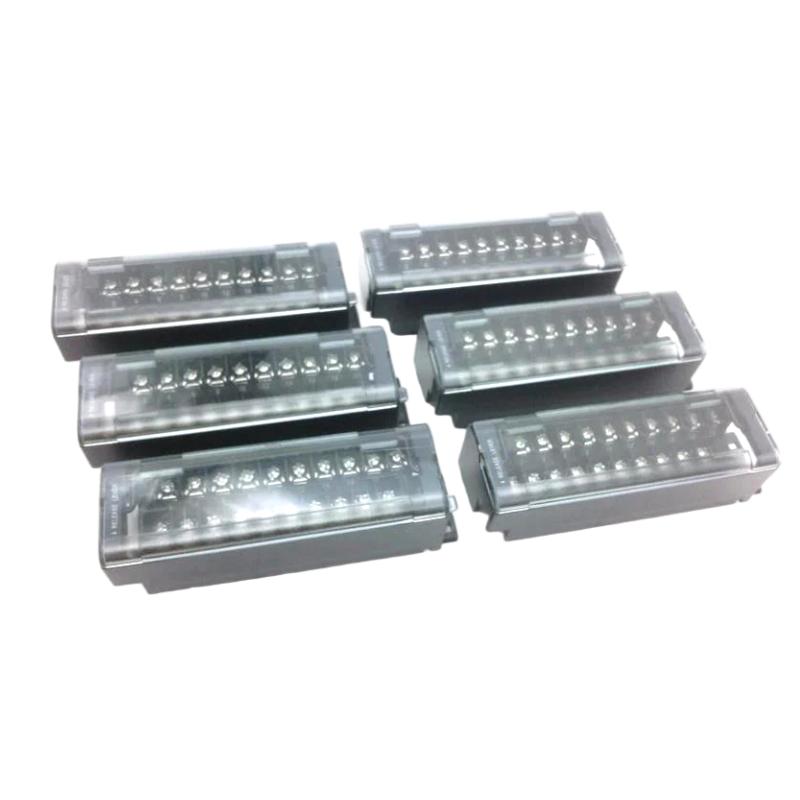
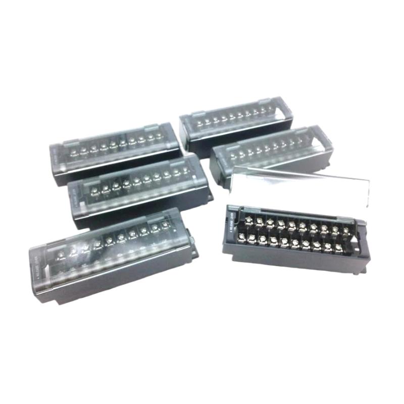
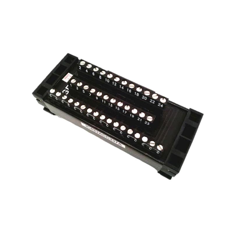
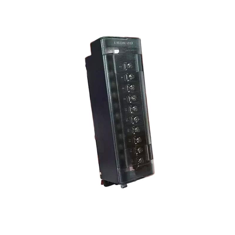
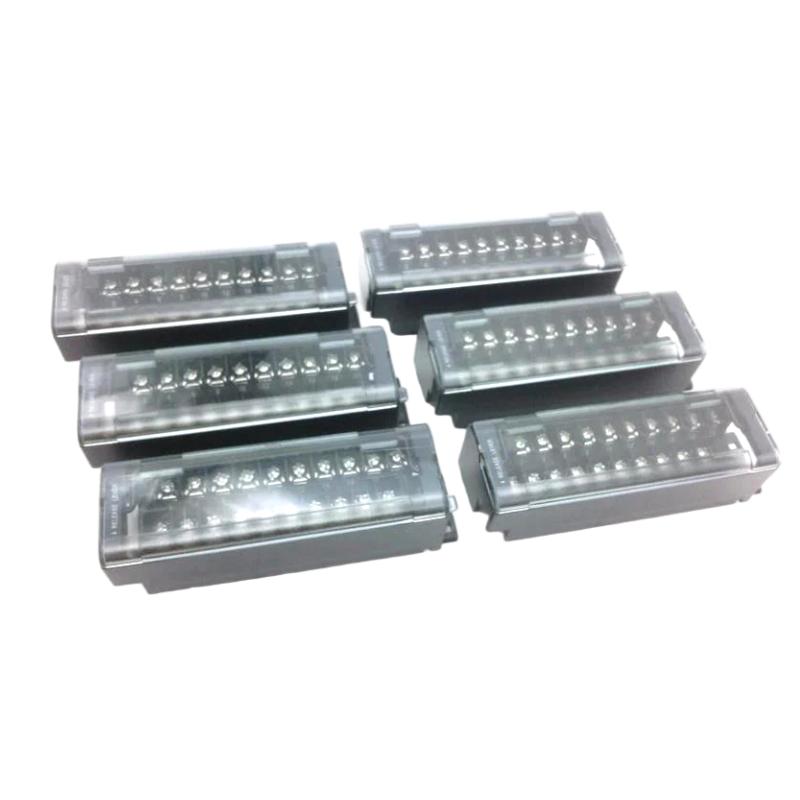
The GE IC694ACC311 Terminal Block is an industrial automation wiring component designed to provide a structured connection point between control-system wiring and compatible PLC or I/O equipment.
Terminal blocks are fundamental components in industrial control cabinets because they provide an organized interface for field wiring, power distribution, signal connections, testing, maintenance, and equipment replacement. Instead of connecting every field conductor directly to internal equipment, a terminal block provides a clearly defined connection point that can simplify cabinet wiring and troubleshooting.
The specified dimensions of the GE IC694ACC311 are 134 × 90 × 35 mm, with a specified weight of 0.8 kg.
This guide covers the terminal block’s function, installation, wiring considerations, commissioning, troubleshooting, preventive maintenance, and replacement practices.
Product Identification
| Parameter | Specification |
|---|---|
| Manufacturer | GE |
| Series | IC694 |
| Model | IC694ACC311 |
| Product Type | Terminal Block |
| Main Function | Field Wiring Interface |
| Application | Industrial Automation |
| Dimensions | 134 × 90 × 35 mm |
| Weight | 0.8 kg |
| Installation | PLC / Control Cabinet |
| Function | Electrical Connection and Distribution |
| Typical Application | PLC and I/O Wiring |
| Maintenance | Terminal and Wiring Inspection |
Technical Specifications
| Technical Item | Specification |
|---|---|
| Manufacturer | GE |
| Model | IC694ACC311 |
| Product Category | Terminal Block |
| Application | Industrial Control |
| Main Role | Field Wiring Interface |
| Dimensions | 134 × 90 × 35 mm |
| Weight | 0.8 kg |
| Installation Environment | Industrial Control Cabinet |
| Wiring Function | Signal / Control Connections |
| Maintenance | Inspection and Retightening According to Procedure |
| System Integration | Compatible PLC / I/O Equipment |
The exact terminal arrangement, conductor size, voltage rating, current rating, connector configuration, and supported equipment should be verified against the applicable system design before installation.
What Is the GE IC694ACC311?
The IC694ACC311 is a terminal block used as part of an industrial control-system wiring architecture.
A typical PLC connection can be represented as:
Field Device
↓
Field Wiring
↓
IC694ACC311 Terminal Block
↓
PLC / I/O Equipment
↓
Controller
The terminal block provides an organized transition between field wiring and control-system equipment.
Depending on the application, connected circuits may include:
- Discrete inputs
- Discrete outputs
- Analog signals
- Control power
- Relay circuits
- Instrumentation wiring
- Interposing relay circuits
The exact application depends on the compatible equipment and terminal configuration.
Role in Industrial Automation
A properly organized terminal system provides several practical benefits.
Wiring Organization
Terminal blocks group field circuits into a defined physical location.
Maintenance
Technicians can identify and test individual circuits more easily.
Troubleshooting
A terminal block provides a convenient point for checking:
- Voltage
- Continuity
- Signal presence
- Wiring integrity
Equipment Replacement
Organized field wiring can make module replacement more manageable because conductors can be clearly identified and documented.
Cabinet Standardization
Terminal blocks help maintain consistent control-panel wiring practices.
Installation Guide
Step 1 – Verify the Model
Before installation, confirm:
GE IC694ACC311
Check the identification label and compare the terminal block with the intended system configuration.
Do not assume that a visually similar terminal block has the same electrical arrangement.
Step 2 – Confirm System Compatibility
Before wiring, identify:
- PLC or I/O system
- Rack configuration
- Associated module
- Terminal assignment
- Field devices
- Voltage level
- Current requirements
- Conductor size
The terminal block must be compatible with the equipment and wiring architecture.
Step 3 – Inspect the Terminal Block
Before installation, inspect the component for:
- Cracks
- Broken terminal sections
- Damaged connectors
- Bent contacts
- Corrosion
- Contamination
- Loose hardware
- Physical deformation
Do not install a damaged terminal block.
Step 4 – Verify Physical Dimensions
The specified dimensions are:
134 × 90 × 35 mm
Ensure adequate space for:
- Terminal block installation
- Wire entry
- Cable bending
- Labeling
- Testing
- Maintenance
- Adjacent components
The terminal block should remain accessible after cabinet assembly.
Step 5 – Consider the Weight
The specified weight is:
0.8 kg
The mounting arrangement should safely support the component and connected wiring.
Field cables should not place excessive mechanical stress on the terminal block.
Step 6 – Isolate Electrical Power
Before wiring:
- Place the machine in a safe condition.
- Isolate applicable power sources.
- Apply lockout/tagout procedures.
- Verify absence of hazardous voltage.
- Confirm stored energy has been addressed.
- Follow site electrical-safety procedures.
Terminal blocks can carry hazardous control or field voltages.
Step 7 – Prepare the Wiring
Before connecting conductors:
- Identify each wire.
- Confirm the terminal number.
- Verify the circuit drawing.
- Check conductor size.
- Check insulation condition.
- Confirm voltage level.
- Prepare appropriate wire ends.
Use correctly sized conductors and suitable termination methods.
Step 8 – Connect the Conductors
Connect each conductor according to the approved wiring diagram.
Verify:
- Correct terminal
- Correct conductor
- Correct circuit
- Correct polarity where applicable
- Proper insertion
- Secure termination
Avoid excessive stripping of insulation.
Step 9 – Label Each Circuit
Clear labeling is essential for industrial maintenance.
Recommended information may include:
- Device tag
- PLC address
- Terminal number
- Signal type
- Voltage level
- Cable identification
Good labeling can significantly reduce troubleshooting time.
Step 10 – Inspect the Completed Wiring
After wiring, inspect:
- Loose conductors
- Exposed copper
- Incorrect terminals
- Crossed wires
- Damaged insulation
- Cable tension
- Terminal screws or clamps
- Wire labels
Perform continuity checks where appropriate before energizing the system.
Wiring Best Practices
Maintain Separation
Where required by the electrical design, keep different circuit categories separated.
Examples include:
- High-voltage power
- Low-voltage control
- Analog instrumentation
- Communication cables
- Relay outputs
This can reduce interference and improve serviceability.
Avoid Excessive Wire Tension
Field wiring should have sufficient slack for maintenance but should not hang heavily from the terminal block.
Excessive tension can cause:
- Loose terminals
- Broken conductors
- Mechanical stress
- Intermittent signals
Maintain Clear Identification
Every important field circuit should be traceable from:
Field Device → Cable → Terminal → I/O Channel → PLC Address
This is particularly valuable during fault diagnosis.
Commissioning Procedure
Pre-Power Inspection
Before applying power:
- Verify terminal assignments.
- Check all wiring.
- Confirm polarity.
- Check for shorts.
- Verify protective devices.
- Confirm grounding.
- Verify wire labels.
- Inspect terminal tightness.
- Compare wiring against drawings.
Continuity Testing
Where applicable, use a suitable test instrument to verify circuit continuity.
Test:
- Field wiring
- Terminal connections
- Jumper connections
- Return paths
Do not perform resistance or continuity testing on energized circuits.
Voltage Verification
After safe energization, verify the expected voltage at appropriate test points.
Check:
- Control power
- Field supply
- Signal voltage
- Return voltage
- Reference voltage
Unexpected voltage may indicate a wiring or power-distribution problem.
Signal Verification
For I/O applications, verify that signals arrive correctly at the intended PLC channels.
For example:
Field Sensor
↓
IC694ACC311
↓
Input Channel
↓
PLC
Confirm that the physical field condition corresponds to the PLC input state.
Troubleshooting Guide
Fault 1 – No Signal at PLC Input
Possible Causes
- Open field wire
- Loose terminal
- Incorrect terminal assignment
- Failed field device
- Missing field power
- Incorrect PLC channel
- Damaged connection
Diagnostic Procedure
Check the circuit progressively:
Field Device → Terminal Block → I/O Channel
Measure the signal at each appropriate point.
Fault 2 – Intermittent Signal
Possible Causes
- Loose terminal
- Broken conductor
- Vibration
- Corrosion
- Poor termination
- Cable damage
- Electrical interference
Corrective Action
Inspect the complete circuit and gently test for mechanical instability according to safe maintenance procedures.
Fault 3 – Terminal Overheating
Possible Causes
- Loose connection
- Excessive current
- Incorrect conductor size
- High contact resistance
- Damaged terminal
- Overloaded circuit
Corrective Action
Remove the circuit from service safely and investigate the cause before reconnecting it.
A hot terminal should never be ignored.
Fault 4 – Short Circuit
Possible Causes
- Miswiring
- Exposed conductor
- Damaged insulation
- Incorrect jumper
- Foreign conductive material
Inspect the terminal block and surrounding wiring.
Fault 5 – Incorrect Signal at PLC
Possible Causes
- Wrong terminal
- Crossed wires
- Incorrect polarity
- Incorrect signal reference
- Misidentified field device
- Wiring documentation error
Compare actual wiring with the approved electrical schematic.
Fault 6 – Multiple Signals Lost
If several signals disappear simultaneously, investigate common causes first.
Possible causes include:
- Common field power loss
- Shared terminal connection
- Common return failure
- Damaged connector
- I/O power problem
- Rack or module issue
Do not immediately replace multiple field devices.
Fault 7 – Terminal Connection Becomes Loose
Possible Causes
- Vibration
- Incorrect tightening
- Repeated maintenance
- Wire movement
- Improper conductor preparation
Inspect the terminal according to the applicable maintenance procedure.
Fault 8 – Communication or Analog Signal Interference
For sensitive signals, possible causes include:
- Poor cable routing
- Grounding problems
- Electrical noise
- Incorrect shielding
- High-current conductors nearby
- Poor terminal connections
Separate sensitive instrumentation wiring from major noise sources where practical.
Fault Diagnosis Flow
A useful troubleshooting sequence is:
Field Device
↓
Field Cable
↓
IC694ACC311 Terminal
↓
I/O Wiring
↓
PLC Module
↓
PLC Program
This method helps identify whether the fault originates in the field device, wiring, terminal block, I/O hardware, or software.
Preventive Maintenance
Terminal Inspection
During scheduled maintenance, inspect:
- Terminal condition
- Wire insertion
- Connector condition
- Labels
- Corrosion
- Discoloration
- Signs of heating
Wiring Inspection
Check for:
- Cracked insulation
- Abrasion
- Loose wires
- Broken conductors
- Incorrect labels
- Excessive cable tension
Thermal Inspection
If permitted by the plant’s maintenance program, thermal inspection can help identify abnormal connections.
A terminal with unusually high temperature compared with similar circuits may indicate:
- Loose connection
- Overload
- Contact resistance
- Wiring problem
Documentation Maintenance
Whenever wiring changes occur, update:
- Electrical drawings
- Terminal schedules
- PLC I/O lists
- Cable schedules
- Device tags
- Maintenance records
Accurate documentation is part of reliable industrial control maintenance.
Preventive Maintenance Table
| Maintenance Area | Recommended Action |
|---|---|
| Terminal Housing | Inspect for damage |
| Terminals | Check mechanical integrity |
| Wiring | Inspect insulation |
| Labels | Verify readability |
| Connections | Check according to maintenance procedure |
| Temperature | Investigate abnormal heating |
| Corrosion | Inspect and correct environmental causes |
| Cable Routing | Maintain proper separation |
| Documentation | Keep drawings current |
| Field Devices | Verify circuit operation |
| PLC I/O | Confirm expected signal behavior |
Applications
PLC Digital I/O
Terminal blocks can organize discrete field signals such as:
- Pushbuttons
- Limit switches
- Proximity sensors
- Solenoids
- Contactors
- Alarm devices
Analog Instrumentation
Where compatible with the terminal arrangement, organized termination can simplify:
- Sensor wiring
- Transmitter wiring
- Signal testing
- Shielding management
Control Power Distribution
Terminal systems can provide organized connection points for appropriately designed control-power circuits.
Maintenance and Testing
Terminal points can make it easier for technicians to access circuits for inspection and testing without disturbing the entire control cabinet.
Industrial Control Cabinet Integration
A well-designed wiring architecture can be organized as:
Field Equipment
↓
Field Cable
↓
IC694ACC311 Terminal Block
↓
PLC / I/O Module
↓
Controller
This arrangement improves traceability and can make future maintenance easier.
Replacement Procedure
When replacing an IC694ACC311:
1. Record Existing Wiring
Document each connected conductor before removal.
2. Isolate Power
Follow lockout/tagout procedures and verify zero-energy conditions where required.
3. Label Conductors
Ensure every conductor can be returned to its original terminal.
4. Remove Existing Terminal Block
Disconnect wiring carefully and remove the component according to the installation structure.
5. Inspect Wiring
Check for:
- Damaged insulation
- Loose strands
- Corrosion
- Broken conductors
6. Install Replacement
Install the new terminal block securely.
7. Reconnect Wiring
Reconnect each conductor according to the documented terminal schedule.
8. Verify
Perform continuity, insulation, voltage, and signal checks as applicable.
Replacement Considerations
When selecting a replacement, verify:
| Parameter | Required Check |
|---|---|
| Model | GE IC694ACC311 |
| Product Type | Terminal Block |
| Dimensions | 134 × 90 × 35 mm |
| Weight | 0.8 kg |
| Rack / System Compatibility | Confirm |
| Terminal Arrangement | Confirm |
| Voltage Rating | Confirm |
| Current Rating | Confirm |
| Conductor Size | Confirm |
| Mounting | Confirm |
| Field Wiring | Confirm |
The physical dimensions alone should not be used to determine compatibility.
Key Advantages
- Provides an organized field-wiring interface
- Supports structured PLC cabinet wiring
- Simplifies circuit identification
- Facilitates maintenance and testing
- Helps improve wiring traceability
- Supports orderly field-device connections
- Useful for industrial control-panel applications
- Dimensions: 134 × 90 × 35 mm
- Weight: 0.8 kg
- Can simplify troubleshooting access
- Supports cleaner cabinet documentation and organization
Technical FAQs
What is the GE IC694ACC311?
The GE IC694ACC311 is identified as a terminal block for industrial automation and control-system wiring applications.
What are the dimensions of the IC694ACC311?
The specified dimensions are 134 × 90 × 35 mm.
What is the weight of the IC694ACC311?
The specified weight is 0.8 kg.
What is the main purpose of a terminal block?
A terminal block provides an organized connection point between field wiring and control-system equipment.
Why are terminal blocks important in PLC cabinets?
They improve wiring organization, circuit identification, testing, maintenance, and troubleshooting.
Can a terminal block replace a PLC I/O module?
No. A terminal block is primarily a wiring interface. It does not perform the processing or signal-conditioning functions of a PLC I/O module unless specifically designed as part of an integrated I/O termination system.
Why is a terminal connection overheating?
Common causes include loose connections, excessive current, unsuitable conductor size, damaged terminals, or increased contact resistance.
What should be checked when a PLC input receives no signal?
Check the field device, field power, cable, terminal connection, I/O wiring, and PLC input channel systematically.
Why can an intermittent signal occur?
Loose terminals, damaged conductors, vibration, corrosion, poor termination, electrical interference, and unstable field devices can all cause intermittent signals.
Should terminal wiring be labeled?
Yes. Clear terminal and field-device identification greatly improves troubleshooting and maintenance efficiency.
Can terminal blocks be used for analog signals?
That depends on the specific terminal block configuration and system design. Analog circuits require careful consideration of signal type, shielding, grounding, and electrical characteristics.
What should be checked before replacing the IC694ACC311?
Confirm the exact model, terminal arrangement, system compatibility, physical dimensions, electrical ratings, mounting arrangement, and wiring requirements.
Conclusion
The GE IC694ACC311 Terminal Block is an important wiring-interface component for compatible industrial automation systems. Its primary purpose is to provide an organized and accessible connection point between field wiring and PLC or I/O equipment.
The specified dimensions are 134 × 90 × 35 mm, with a specified weight of 0.8 kg. These physical characteristics should be considered when designing cabinet layouts and planning maintenance access.
Reliable terminal-block operation depends on correct wiring, secure connections, appropriate conductor selection, clear labeling, suitable environmental conditions, and accurate electrical documentation. During commissioning, every important circuit should be checked from the field device through the terminal block to the PLC I/O point.
For troubleshooting, a systematic path from field device → cable → terminal block → I/O module → PLC program can quickly isolate many common faults. Preventive inspection of terminals, wiring, temperature, corrosion, and mechanical condition can further reduce the risk of intermittent signals, overheating, and unexpected control-system downtime.