

ProductPRODUCT
Featured products



Contact Us
- GE
- IC693MOL646
- Relay Output Module
- USA
- 120 × 90 × 40 mm
- 0.35 kg
- Xiamen, China
- New & In Stock
- T/T, PayPal, Western Union
- 1 Year
- 1-3 Working Days
- DHL, UPS, TNT, FedEx and EMS.
- 24-Hour Service
- COO
- 37
Our advantage

Global Logistics
We have a 10-year logistics and express cooperation agreement, so our products can be shipped to any place in the world.

Brand new and original
Our products are imported in bulk from the place of origin. Because of the cooperative relationship, our products are all original and 100% new.

24-hour service
We provide 7*24 hours service to our customers. We will be there whenever you need us.

Price advantage
All our products are priced very favorably because we have our own warehouse and supply.
| Company Information | |||
| [email protected] | |||
| Mobile | +8615980777398 | ||
| +8615980777398 | |||
| 15980777398 |
Product Overview
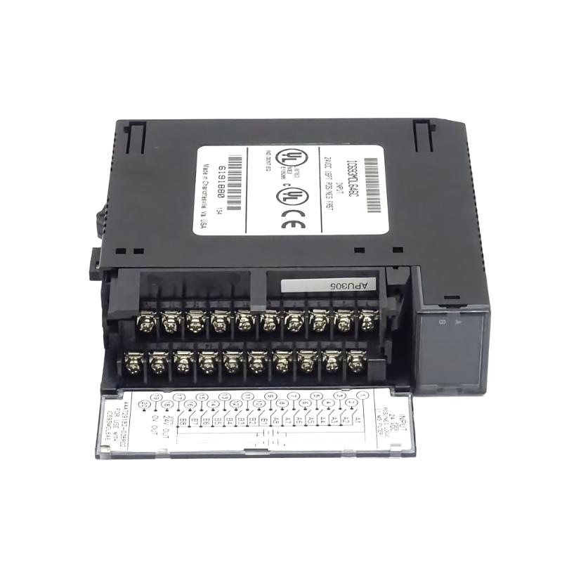
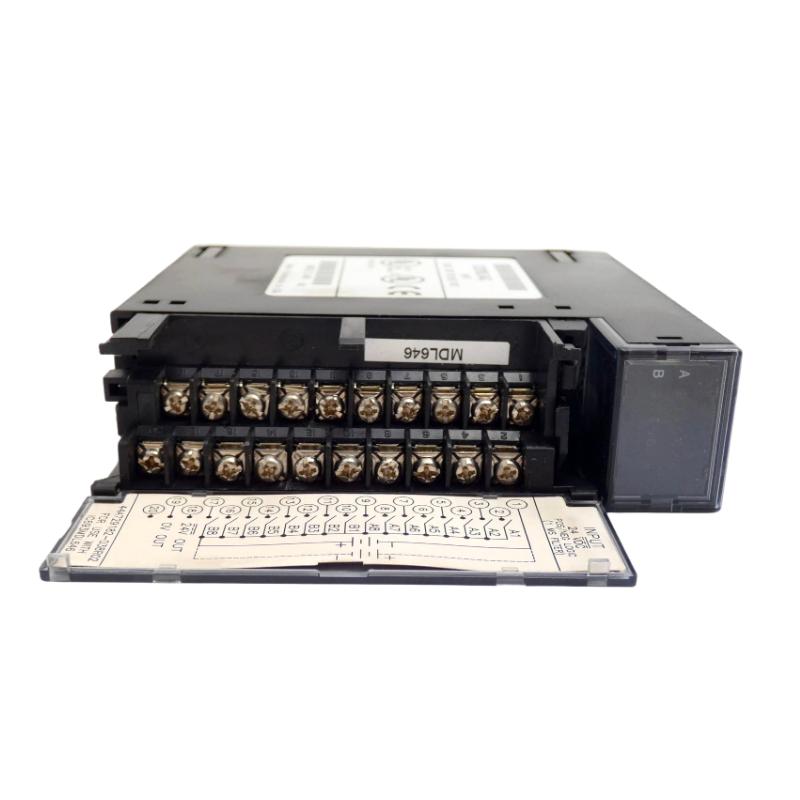
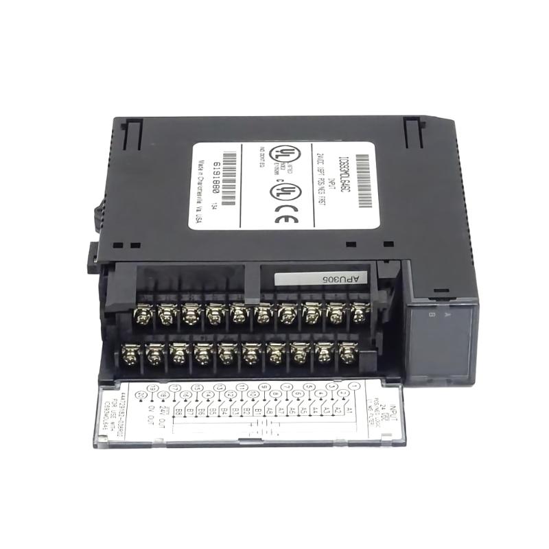
The GE IC693MOL646 Relay Output Module is an industrial automation output component designed to interface a control system with external loads through relay-based switching. Within a PLC architecture, an output module acts as the connection point between controller logic and field equipment such as contactors, solenoid valves, indicator devices, interposing relays, and other discrete loads.
Relay outputs are particularly useful where electrical isolation and flexible load switching are required. Unlike a purely electronic transistor output, a relay output uses mechanical switching contacts, allowing the output circuit to control compatible loads according to the electrical design of the system.
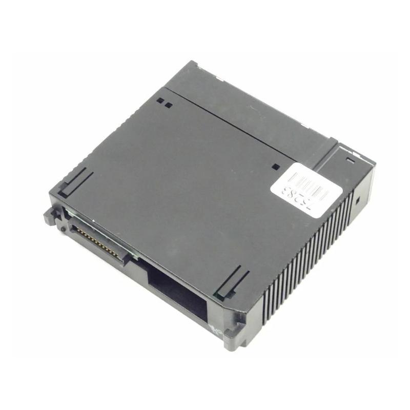
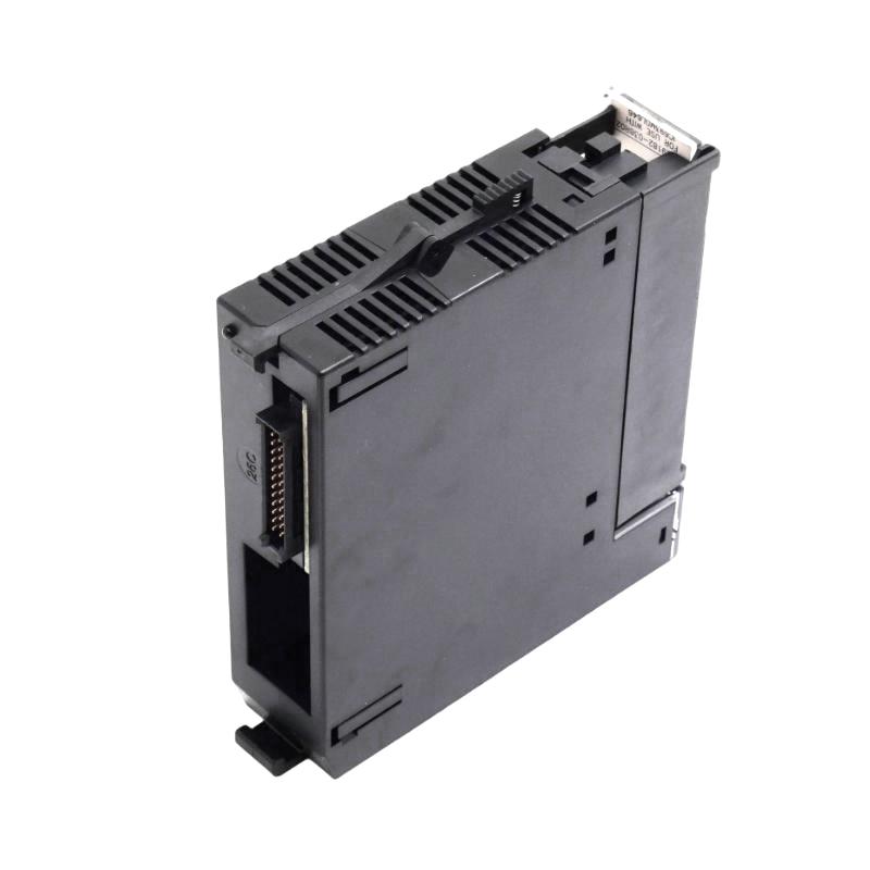
The specified physical dimensions of the GE IC693MOL646 are 120 × 90 × 40 mm, with a specified weight of 0.35 kg.
This guide explains the module’s role, installation considerations, wiring practices, commissioning procedure, fault diagnosis, preventive maintenance, and replacement considerations.
Product Identification
| Parameter | Specification |
|---|---|
| Manufacturer | GE |
| Series | IC693 |
| Model | IC693MOL646 |
| Product Type | Relay Output Module |
| Main Function | Discrete Relay Output Control |
| Application | Industrial Automation |
| Dimensions | 120 × 90 × 40 mm |
| Weight | 0.35 kg |
| Installation | PLC / Control System |
| Output Type | Relay |
| Typical Loads | Relays, Contactors, Solenoids, Indicators |
| Maintenance | Electrical and Mechanical Inspection |
Technical Specifications
| Technical Item | Specification |
|---|---|
| Manufacturer | GE |
| Model | IC693MOL646 |
| Product Category | Relay Output Module |
| Application | PLC Control |
| Output Technology | Relay Contacts |
| Dimensions | 120 × 90 × 40 mm |
| Weight | 0.35 kg |
| Installation Environment | Industrial Control Cabinet |
| Function | Switches external discrete loads |
| System Integration | PLC / I/O System |
| Typical Application | Machine Control and Process Automation |
| Maintenance | Contact, wiring, and terminal inspection |
The exact channel count, contact ratings, allowable load types, electrical isolation characteristics, terminal assignment, and voltage/current limits should be confirmed against the specific module documentation before wiring the IC693MOL646.
Role in an Industrial Control System
The IC693MOL646 occupies the output side of a PLC control architecture.
A simplified control path is:
PLC Program
↓
CPU / Controller
↓
IC693MOL646 Relay Output Module
↓
Relay Contact
↓
External Load
↓
Machine / Process
The controller determines when an output should turn ON or OFF. The relay output module then switches the corresponding external circuit.
Typical applications can include:
- Motor contactors
- Solenoid valves
- Pilot relays
- Alarm circuits
- Indicator lamps
- Control circuits
- Interposing relays
- Discrete actuators
The module therefore provides an important interface between low-level PLC logic and external electrical equipment.
How a Relay Output Works
A relay output uses an electrically controlled switching mechanism.
A simplified sequence is:
PLC Logic = ON
↓
Output Circuit Energizes
↓
Relay Contact Changes State
↓
External Load Receives Power
↓
Device Operates
When the PLC logic changes to OFF, the relay returns to its designated inactive state and the external load is disconnected or changes state according to the circuit design.
This architecture provides a useful degree of electrical separation between the PLC control electronics and the field circuit.
Relay Output vs. Electronic Output
Relay outputs and solid-state outputs have different characteristics.
| Characteristic | Relay Output | Solid-State Output |
|---|---|---|
| Switching Method | Mechanical contact | Semiconductor |
| Electrical Isolation | Typically available through contacts | Depends on design |
| Mechanical Wear | Yes | No mechanical contact |
| Switching Speed | Generally slower | Generally faster |
| Load Flexibility | Often broad within ratings | Depends on output type |
| High-Frequency Switching | Not ideal | Better suited |
| Contact Aging | Possible | No mechanical contact |
The IC693MOL646 should therefore be applied according to the actual load, switching frequency, voltage, current, and electrical environment.
Installation Guide
1. Verify the Module
Before installation, confirm:
GE IC693MOL646
Inspect the module for:
- Cracked housing
- Damaged terminals
- Bent connectors
- Corrosion
- Contamination
- Burn marks
- Loose components
- Mechanical damage
Do not install a visibly damaged module.
2. Confirm Electrical Compatibility
Before connecting field wiring, verify the required electrical characteristics.
Important parameters include:
- Output voltage
- Output current
- AC or DC load
- Contact configuration
- Load type
- Switching frequency
- Inrush current
- Protective requirements
The relay contact rating must be suitable for the actual connected load.
3. Evaluate the Load
Do not select a relay output only from the normal operating current.
Consider:
- Continuous current
- Starting current
- Inrush current
- Inductive load characteristics
- Motor contactor coil behavior
- Solenoid characteristics
- Switching frequency
Inductive loads can generate significant transient voltage when switched.
Appropriate suppression and protection should be considered according to the electrical design.
4. Cabinet Installation
The specified dimensions are:
120 × 90 × 40 mm
Reserve sufficient cabinet space for:
- Module installation
- Wiring
- Terminal access
- Cable bending
- Ventilation
- Maintenance
Avoid placing high-heat equipment immediately next to the output module.
5. Mounting
The specified weight is:
0.35 kg
The module should be securely mounted within the compatible PLC rack or installation structure.
Check:
- Mechanical alignment
- Retaining hardware
- Connector seating
- Rack stability
- Vibration
- Wiring support
Do not allow external wiring to place mechanical stress on the module.
6. Power Isolation
Before wiring the module:
- Shut down the appropriate equipment.
- Disconnect hazardous electrical power.
- Apply lockout/tagout procedures.
- Verify the absence of voltage.
- Confirm that external loads cannot unexpectedly energize.
- Follow the plant’s electrical safety procedures.
Relay output wiring can involve hazardous field voltages, so safe isolation is essential.
Wiring Considerations
Field Circuit Wiring
Connect field loads according to the approved electrical schematic.
Verify:
- Correct terminal
- Correct contact arrangement
- Correct voltage
- Correct polarity where applicable
- Correct load
- Correct protection
- Terminal tightness
Never rely on assumed terminal assignments.
Inductive Loads
Applications involving:
- Contactors
- Solenoid valves
- Relays
- Electromagnetic devices
may produce voltage transients when the relay opens.
Suitable suppression methods may include appropriately selected:
- Flyback diodes for suitable DC coils
- RC suppression for suitable AC loads
- Surge suppression devices
The suppression method must match the load voltage and electrical characteristics.
Output Protection
External protection should be designed according to the connected load and plant electrical standards.
Consider:
- Fuses
- Circuit breakers
- Surge suppression
- Overcurrent protection
- Separate branch protection
The output module should not be expected to compensate for an incorrectly designed field circuit.
Commissioning Procedure
Pre-Power Inspection
Before energizing:
- Verify the module model.
- Confirm rack installation.
- Check connector seating.
- Verify field wiring.
- Confirm load voltage.
- Check protective devices.
- Verify grounding where required.
- Inspect for short circuits.
- Confirm the PLC configuration.
- Check output addressing.
Initial Power-Up
Apply power and inspect the PLC system.
Check:
- Controller status
- Module status
- Diagnostic indicators
- Communication status
- Unexpected output activation
If an output becomes active unexpectedly, stop the commissioning sequence and verify the PLC logic and wiring.
Output Testing
Test each required output according to the commissioning plan.
For each channel:
- Activate the output from the PLC.
- Confirm the expected relay response.
- Verify the external load.
- Deactivate the output.
- Confirm the load turns off.
- Record abnormal behavior.
Do not test high-energy loads without appropriate safety controls.
Verify Actual Load Behavior
A relay output can appear to operate correctly while the connected device does not.
Therefore, verify both:
Relay Operation
and
Field Device Operation
For example, if a PLC output changes state but a solenoid does not activate, investigate the field circuit rather than assuming that the PLC output module has failed.
Troubleshooting Guide
Fault 1 – Output Does Not Turn ON
Possible Causes
- PLC logic does not command the output
- Incorrect output address
- Module configuration problem
- Field wiring problem
- Relay contact failure
- External power missing
- Load failure
Diagnostic Procedure
Check:
- PLC logic.
- Output status.
- Module diagnostics.
- Field voltage.
- Wiring.
- Relay contact behavior.
- Load condition.
Fault 2 – Output Remains OFF
If the PLC indicates the output is ON but the load remains OFF, inspect the complete field circuit.
Possible causes include:
- No field supply
- Open circuit
- Incorrect terminal
- Failed load
- Damaged relay contact
- Loose connection
- Protective device open
Fault 3 – Output Remains ON
Possible Causes
- Relay contact welded
- PLC logic continuously commands ON
- Incorrect wiring
- Short circuit around the relay contact
- External circuit problem
Mechanical relay contacts can become welded if subjected to excessive current or severe inrush.
Fault 4 – Relay Clicks but Load Does Not Operate
A clicking relay does not necessarily prove that the complete output circuit is healthy.
Possible causes:
- Open field circuit
- Missing load power
- Failed load
- Incorrect wiring
- Damaged contact
- High contact resistance
Measure the field circuit using an appropriate electrical test procedure.
Fault 5 – Output Works Intermittently
Possible Causes
- Loose terminal
- Worn relay contacts
- Excessive vibration
- Inductive transients
- PLC logic instability
- Field power instability
- Damaged wiring
Inspect both the module and the field circuit.
Fault 6 – Relay Contact Fails Prematurely
Possible Causes
- Excessive load current
- High inrush current
- Incorrect load type
- Excessive switching frequency
- Insufficient suppression
- Electrical arcing
Review the actual load characteristics rather than only its nominal operating current.
Fault 7 – Module Shows a Diagnostic Fault
Possible Causes
- Poor rack connection
- Configuration mismatch
- Module hardware fault
- Power problem
- Controller issue
Check the module seating, configuration, controller diagnostics, and system power.
Fault 8 – Multiple Outputs Fail Simultaneously
If multiple output channels fail together, investigate common causes first.
Possible causes:
- PLC power problem
- Rack power problem
- Controller fault
- Configuration issue
- Common field power loss
- Module-level failure
Replacing individual loads without checking the common source can waste troubleshooting time.
Fault 9 – External Fuse Trips
Possible Causes
- Short circuit
- Excessive load
- Incorrect wiring
- Failed actuator
- Excessive inrush
- Incorrect protective-device selection
Locate the field-circuit problem before repeatedly replacing the fuse.
Fault 10 – Relay Output Becomes Hot
Possible Causes
- Excessive current
- Poor terminal connection
- Contact resistance
- Overloaded circuit
- Excessive switching
- Ambient temperature
Inspect the load and wiring immediately if abnormal heating is detected.
Fault Diagnosis Flow
A systematic troubleshooting sequence is:
PLC Program
↓
Output Command
↓
IC693MOL646 Status
↓
Relay Operation
↓
Output Contact
↓
Field Power
↓
Wiring
↓
External Load
This sequence helps isolate logic problems from module problems and field-device problems.
Preventive Maintenance
Module Inspection
During scheduled maintenance, inspect:
- Module housing
- Terminals
- Connectors
- Status indicators
- Signs of overheating
- Discoloration
- Dust accumulation
- Corrosion
Relay Contact Maintenance
Relay contacts are mechanical components and can experience wear over time.
Monitor for:
- Contact resistance increase
- Intermittent switching
- Contact welding
- Arcing
- Delayed switching
- Failure to open
The service life of relay contacts depends strongly on load type and switching frequency.
Load Review
Periodically review connected loads.
Pay particular attention to changes such as:
- Larger contactor coils
- New solenoid valves
- Increased switching frequency
- Motor-control modifications
- New field devices
A circuit that was suitable during initial commissioning may become unsuitable after a machine modification.
Terminal Inspection
Loose terminals can produce:
- Heating
- Voltage drop
- Intermittent operation
- Arcing
- Contact damage
Inspect terminals during scheduled maintenance according to plant procedures.
Preventive Maintenance Table
| Maintenance Area | Recommended Action |
|---|---|
| Module Housing | Inspect for physical damage |
| Terminals | Check connection integrity |
| Rack Connection | Verify secure seating |
| Relay Contacts | Monitor switching behavior |
| Field Wiring | Inspect insulation and connections |
| Load Current | Confirm within design limits |
| Inductive Loads | Check suppression |
| Temperature | Monitor abnormal heating |
| Status Indicators | Check for diagnostics |
| Cabinet | Keep clean and ventilated |
| Output Testing | Verify during scheduled maintenance |
| PLC Program | Confirm output logic and addressing |
Applications
The IC693MOL646 relay output function can be useful in applications involving discrete load control.
Motor Control
The relay output can control an appropriate motor starter or contactor circuit rather than directly switching a motor unless the complete electrical design specifically permits it.
Solenoid Control
Relay outputs can be used for compatible solenoid control circuits.
Alarm Systems
The module can be used to switch compatible alarm or annunciator circuits.
Indicator Devices
Discrete outputs can control indicator lamps or signaling equipment when the load is within the applicable electrical ratings.
Interposing Relay Applications
The output can control an intermediate relay where additional isolation or load-handling capability is required.
Industrial System Integration
A typical architecture is:
PLC CPU
↓
IC693MOL646
↓
Interposing Relay / Contactor
↓
Actuator
↓
Industrial Process
The output module is therefore part of a larger control chain.
When a field device fails to respond, troubleshooting should examine every stage rather than replacing the module immediately.
Replacement Considerations
When replacing the IC693MOL646, verify:
Model
GE IC693MOL646
Dimensions
120 × 90 × 40 mm
Weight
0.35 kg
Output Type
Relay output.
Electrical Characteristics
Confirm the actual:
- Contact voltage
- Contact current
- AC/DC capability
- Load category
- Inrush capability
- Switching frequency
Mechanical Compatibility
Verify:
- Rack compatibility
- Mounting
- Connector
- Terminal arrangement
- Cabinet clearance
Key Advantages
- Relay-based discrete output architecture
- Suitable for industrial PLC applications
- Provides switching interface between PLC logic and field loads
- Useful for contactor and relay control
- Suitable for compatible solenoid applications
- Can control indicator and alarm circuits
- Useful for interposing relay applications
- Compact physical dimensions
- Dimensions: 120 × 90 × 40 mm
- Weight: 0.35 kg
- Suitable for control-cabinet integration
- Supports straightforward output diagnostics
Technical FAQs
What is the GE IC693MOL646?
The GE IC693MOL646 is identified as a relay output module for industrial automation applications. It provides relay-based switching between PLC control logic and compatible external loads.
What are the dimensions of the IC693MOL646?
The specified dimensions are 120 × 90 × 40 mm.
What is the weight of the IC693MOL646?
The specified weight is 0.35 kg.
What can a relay output module control?
Depending on the applicable electrical ratings, relay outputs can be used for compatible contactors, relays, solenoids, indicator circuits, alarms, and other discrete loads.
Can the relay output directly drive a motor?
A PLC relay output should generally control an appropriate motor starter or contactor circuit rather than directly switching a motor unless the complete electrical design and ratings specifically permit direct switching.
Why does a relay click but the load does not operate?
Possible causes include missing field power, an open circuit, failed load, incorrect wiring, damaged contacts, or high contact resistance.
Why does a relay output remain ON?
Possible causes include PLC logic commanding the output ON, incorrect wiring, an external bypass, or welded relay contacts.
Why do relay contacts fail prematurely?
Excessive current, high inrush, inductive loads, insufficient suppression, excessive switching frequency, and arcing can all contribute to contact wear.
Why is suppression important for inductive loads?
Inductive loads can generate voltage transients when switched. Appropriate suppression can help reduce electrical stress on relay contacts and surrounding equipment.
What should be checked if multiple outputs fail?
Check common power supplies, PLC status, rack connections, configuration, field power, and module-level conditions before replacing individual components.
How should the IC693MOL646 be maintained?
Inspect the module, rack connection, terminals, wiring, relay behavior, load conditions, temperature, and diagnostic indicators during scheduled maintenance.
What should be verified before replacing the module?
Confirm the model, rack compatibility, terminal arrangement, relay output characteristics, connected load requirements, and physical installation requirements.
Conclusion
The GE IC693MOL646 Relay Output Module provides a relay-based interface between PLC logic and external discrete loads in industrial automation systems. With specified dimensions of 120 × 90 × 40 mm and a weight of 0.35 kg, it can be integrated into compatible PLC and control-panel architectures.
Correct application requires careful consideration of the actual load. Contact voltage, current, inrush characteristics, AC/DC requirements, switching frequency, and inductive-load behavior should all be evaluated before installation.
During commissioning, technicians should verify the PLC output command, relay operation, field power, wiring, and connected load. During troubleshooting, a systematic approach helps distinguish between PLC logic problems, module faults, relay-contact problems, field wiring issues, and failed actuators.
Because relay outputs contain mechanical switching elements, preventive maintenance is particularly important. Monitoring contact behavior, load conditions, terminal integrity, temperature, and switching frequency can help identify developing faults before they cause unexpected machine downtime.