

ProductPRODUCT
Featured products
Contact Us
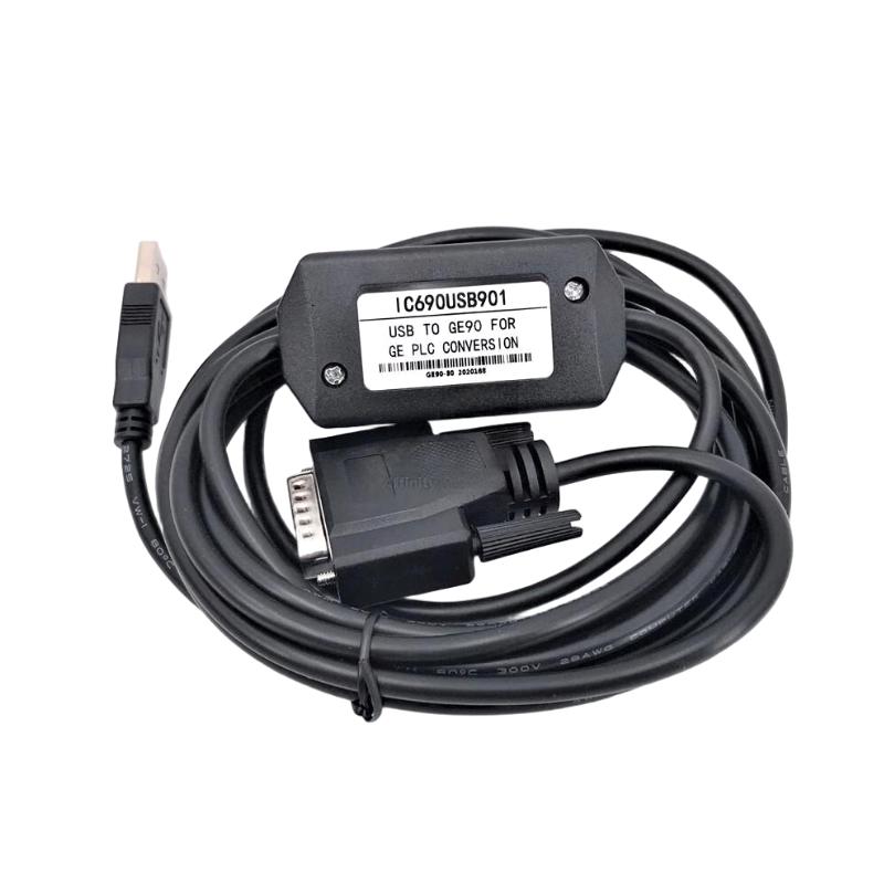
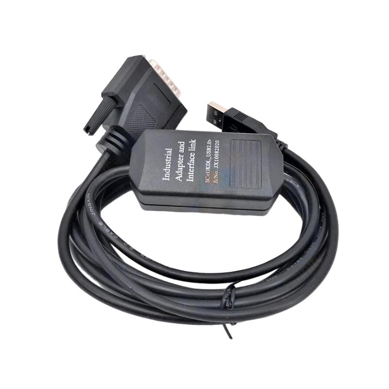
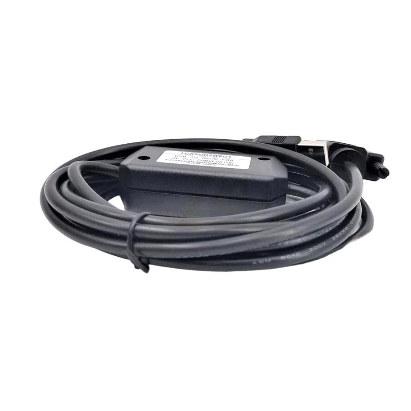
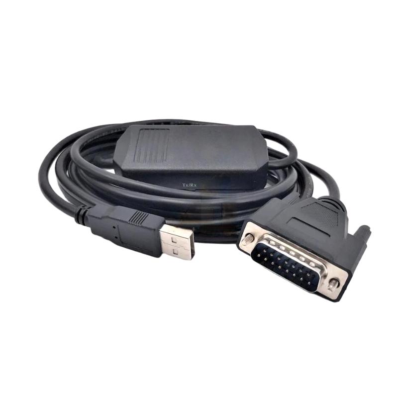
- GE
- GE IC690USB901
- Programming Cable
- USA
- 2.8 meters
- 3 kg
- Xiamen, China
- New & In Stock
- T/T, PayPal, Western Union
- 1 Year
- 1-3 Working Days
- DHL, UPS, TNT, FedEx and EMS.
- 24-Hour Service
- COO
- 42
Our advantage

Global Logistics
We have a 10-year logistics and express cooperation agreement, so our products can be shipped to any place in the world.

Brand new and original
Our products are imported in bulk from the place of origin. Because of the cooperative relationship, our products are all original and 100% new.

24-hour service
We provide 7*24 hours service to our customers. We will be there whenever you need us.

Price advantage
All our products are priced very favorably because we have our own warehouse and supply.
| Company Information | |||
| [email protected] | |||
| Mobile | +8615980777398 | ||
| +8615980777398 | |||
| 15980777398 |
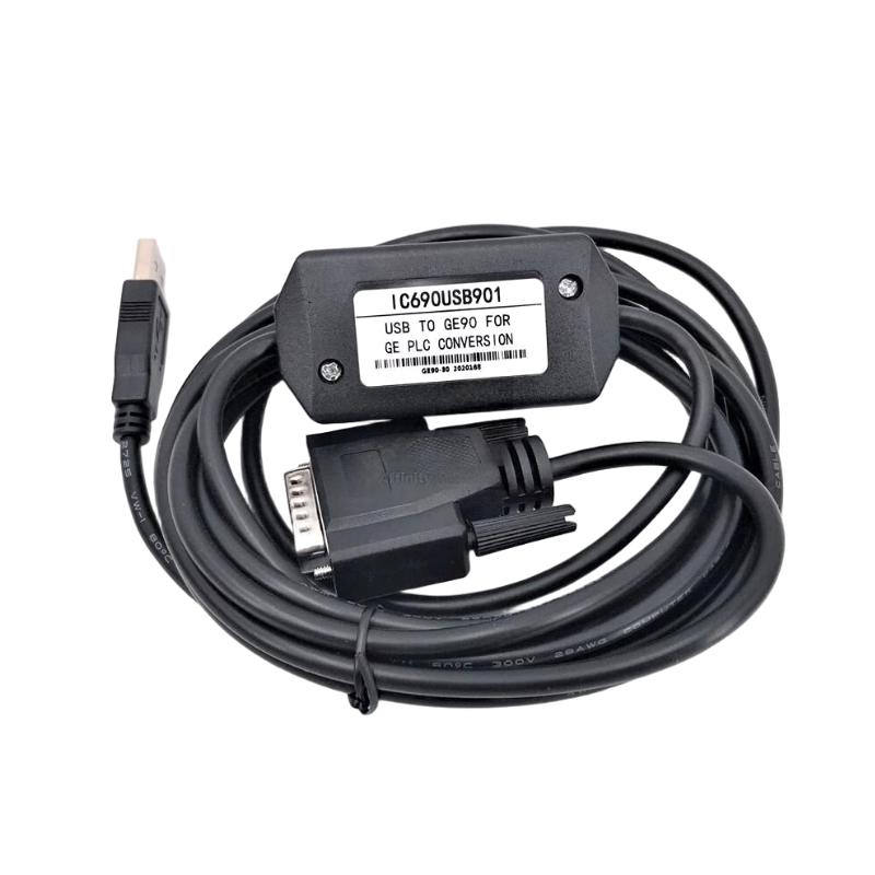
Product Overview
The GE IC690USB901 Programming Cable is an industrial automation programming and communication accessory intended to provide a connection between compatible GE control equipment and a programming or engineering workstation.
Programming cables are essential during PLC commissioning, application development, maintenance, diagnostics, parameter management, and system troubleshooting. A reliable connection allows an engineer or technician to establish communication with the controller, transfer or monitor control programs, review diagnostic information, and perform maintenance activities.
The IC690USB901 has a specified cable length of 2.8 meters and a shipping weight of 3 kg.
Because a programming cable forms the physical connection between an engineering computer and industrial control equipment, correct connector identification, compatible software, communication configuration, driver installation, and proper cable handling are important for reliable operation.
This guide covers installation, connection, commissioning, troubleshooting, maintenance, and practical application considerations for the GE IC690USB901.
Product Identification
| Parameter | Specification |
|---|---|
| Manufacturer | GE |
| Model | IC690USB901 |
| Product Type | Programming Cable |
| Application | PLC Programming and Maintenance |
| Cable Length | 2.8 meters |
| Shipping Weight | 3 kg |
| Primary Function | Controller-to-Engineering Workstation Connection |
| Typical Application | PLC Programming / Diagnostics |
| Installation Type | External Cable Connection |
| Application Environment | Industrial Automation |
Technical Specifications
| Technical Item | IC690USB901 |
|---|---|
| Manufacturer | GE |
| Model | IC690USB901 |
| Product Category | Programming Cable |
| Cable Length | 2.8 m |
| Shipping Weight | 3 kg |
| Main Application | PLC Programming |
| Secondary Application | Diagnostics and Commissioning |
| Connection | Compatible Controller to Engineering Computer |
| Typical User | Automation Engineer / Maintenance Technician |
| Installation | Plug-and-Connect |
| Maintenance | Connector and Cable Inspection |
The exact connector arrangement, communication protocol, driver requirements, and supported controller models should be verified against the specific controller and programming environment before use.
What Is the GE IC690USB901 Used For?
The IC690USB901 is intended to support communication between compatible automation equipment and a programming workstation.
Typical tasks can include:
- PLC program development
- Program upload
- Program download
- Controller monitoring
- Online diagnostics
- Configuration
- Maintenance
- Commissioning
- Fault diagnosis
- Parameter management
- Controller status inspection
A typical connection can be represented as:
Engineering Computer
↓
IC690USB901 Programming Cable
↓
GE Controller
↓
PLC / Automation System
This makes the cable particularly useful during commissioning and service operations.
Role in PLC Engineering
A programming cable is often used at several stages of an automation project’s life cycle.
Engineering
During application development, engineers can use the programming connection to transfer and test control logic.
Commissioning
During machine startup, technicians can use the connection to:
- Monitor PLC operation
- Check controller status
- Review diagnostic information
- Test control sequences
- Verify I/O behavior
Maintenance
During production maintenance, the programming connection can help technicians identify controller faults and inspect system behavior.
Troubleshooting
When a machine stops unexpectedly, online access can provide useful information about:
- Controller status
- Program execution
- Diagnostic conditions
- I/O states
- Communication conditions
- Control logic
Cable Construction and Physical Considerations
The specified cable length is:
2.8 meters
This provides useful working distance between the engineering computer and the controller while keeping the connection relatively manageable inside or around a control cabinet.
The cable should be routed carefully to prevent:
- Excessive bending
- Mechanical stress
- Crushing
- Abrasion
- Connector tension
- Exposure to excessive heat
Do not use the cable as a lifting device or allow its weight to hang from a connector.
Installation Guide
Step 1 – Confirm the Cable Model
Verify:
GE IC690USB901
Do not substitute an unidentified cable simply because its connectors appear physically similar.
Programming cables may differ in:
- Pin assignment
- Communication electronics
- Protocol
- Electrical levels
- Driver requirements
- Controller compatibility
Step 2 – Identify the Controller
Before connecting the cable, identify the exact controller or automation equipment being programmed.
Record:
- Controller model
- Controller series
- Communication interface
- Programming software
- Existing communication configuration
Confirm that the IC690USB901 is suitable for the intended controller.
Step 3 – Prepare the Engineering Computer
The engineering workstation should have the required programming or configuration software installed.
Depending on the control system, verify:
- Programming software
- Communication drivers
- USB drivers where applicable
- Controller support
- User permissions
- Communication settings
If the computer does not recognize the cable, check the operating-system device status before assuming that the cable has failed.
Step 4 – Inspect the Cable
Before connection, inspect the complete cable.
Check:
- Connector housing
- Pins
- Cable jacket
- Strain relief
- Connector locking mechanism
- Signs of corrosion
- Cuts
- Crushing
- Abrasion
- Excessive bending
Do not use a cable with exposed conductors or visibly damaged connectors.
Step 5 – Connect the Cable
Connect the appropriate end to the engineering workstation and the compatible end to the controller.
Ensure that:
- The connector is fully inserted.
- The connector is correctly oriented.
- No excessive force is applied.
- The cable is not under mechanical tension.
Do not force a connector that does not fit.
Step 6 – Establish Communication
After connection:
- Start the programming software.
- Select the appropriate controller.
- Select the programming interface.
- Configure the required communication settings.
- Attempt to establish an online connection.
- Verify controller identification.
If communication is successful, confirm that the software identifies the intended controller.
Step 7 – Verify the Controller Before Editing
Before making any changes:
- Upload or back up the existing program where appropriate.
- Save configuration information.
- Record important parameters.
- Verify the correct controller.
- Confirm the correct project file.
This is especially important in facilities containing multiple similar PLC systems.
Programming and Commissioning
Program Upload
A programming cable can be used to retrieve an existing controller program where the controller and software support the operation.
Before uploading:
- Identify the correct controller.
- Establish communication.
- Confirm the controller status.
- Save the retrieved project.
- Store a verified backup.
Program Download
When downloading a program:
- Confirm the correct project.
- Verify controller compatibility.
- Confirm that the machine is in a safe state.
- Review the program.
- Establish communication.
- Transfer the program.
- Verify the controller status.
- Test the application carefully.
Never download an unverified control program to a running production machine without considering the resulting machine behavior.
Online Monitoring
Online monitoring can help engineers observe the behavior of the PLC application.
Potential monitoring tasks include:
- Program execution
- Input status
- Output status
- Internal variables
- Timers
- Counters
- Alarms
- Controller diagnostics
This can make the IC690USB901 useful during commissioning and troubleshooting.
Troubleshooting Guide
Fault 1 – Computer Does Not Recognize the Cable
Possible Causes
- Missing driver
- USB connection problem
- Damaged cable
- Incorrect computer port
- Operating-system issue
- Incompatible cable
Diagnostic Procedure
Check:
- Physical cable connection.
- Computer USB port.
- Operating-system device status.
- Required driver.
- Programming software configuration.
- Cable condition.
Try another known-good compatible computer port where appropriate.
Fault 2 – Cable Is Detected but PLC Cannot Be Reached
Possible Causes
- Incorrect controller selection
- Incorrect communication interface
- Incorrect communication configuration
- Controller not powered
- Cable incompatibility
- Controller communication-port problem
Corrective Action
Verify the complete communication path:
Computer → Cable → Controller
Then confirm that the correct controller and interface have been selected in the programming software.
Fault 3 – Communication Is Intermittent
Possible Causes
- Loose connector
- Damaged cable
- Cable routed through a high-noise environment
- USB port problem
- Driver instability
- Connector contamination
Diagnostic Procedure
Inspect the cable physically.
Then:
- Reseat connectors.
- Try another computer port.
- Check cable routing.
- Inspect the connectors.
- Test with a known-good cable if available.
Fault 4 – Programming Software Reports a Communication Error
Possible Causes
- Wrong communication interface
- Incorrect driver
- Incorrect controller configuration
- Controller unavailable
- Cable not recognized
- Software compatibility problem
Review the software communication settings before replacing hardware.
Fault 5 – Connection Drops During Program Transfer
Possible Causes
- Loose connector
- Damaged cable
- USB port interruption
- Computer power-management behavior
- Driver problem
- Electrical interference
Corrective Action
Ensure that the cable cannot move during data transfer.
Disable inappropriate computer power-management behavior where required by the engineering environment and verify driver stability.
Fault 6 – Programming Connection Is Slow
Possible Causes
- Incorrect communication settings
- Driver problem
- Computer performance
- Controller communication issue
- Excessive electrical interference
Compare the behavior with a known-good workstation and cable if available.
Fault 7 – Controller Cannot Be Programmed After Software Installation
Possible Causes
- Incorrect driver
- Wrong programming software
- Missing controller support
- Incorrect communication interface
- User-permission problem
- Cable compatibility issue
Verify the software environment before concluding that the cable is defective.
Fault 8 – Cable Works on One Computer but Not Another
Possible Causes
- Different driver versions
- Operating-system differences
- USB-port configuration
- User permissions
- Programming software installation
- Computer security restrictions
Compare the two computer configurations.
Fault 9 – Cable Works Intermittently When Moved
Possible Causes
- Internal conductor damage
- Connector strain
- Broken shielding
- Damaged strain relief
A cable that loses communication when physically moved should be treated as suspect and replaced or professionally tested.
Fault 10 – Controller Suddenly Disconnects
Possible Causes
- Connector movement
- Cable damage
- Computer USB power interruption
- Controller power problem
- Driver issue
- Communication-port fault
Check whether the controller itself remains operational while the programming connection is lost.
Troubleshooting Flow
A systematic diagnostic sequence is:
Engineering Computer
↓
USB / Communication Port
↓
Driver
↓
IC690USB901
↓
Cable Connectors
↓
Controller Communication Interface
↓
Controller
↓
Programming Software
This approach helps identify whether the problem is related to the computer, software, cable, connector, or controller.
Cable Routing Guidelines
The 2.8-meter cable provides flexibility, but it should not be routed without considering the industrial environment.
Avoid routing the programming cable directly alongside:
- High-current motor cables
- Variable-frequency drive output cables
- Contactor wiring
- Welding equipment cables
- High-voltage conductors
Where practical, maintain separation from major electrical noise sources.
Cable Protection
Protect the IC690USB901 from:
- Crushing
- Sharp edges
- Moving machinery
- Excessive bending
- High temperatures
- Chemical exposure
- Oil contamination
- Water
- Repeated connector stress
If the cable must cross a cabinet edge, use suitable cable protection.
Maintenance Procedure
Visual Inspection
Inspect the cable periodically for:
- Cuts
- Cracks
- Abrasion
- Connector damage
- Bent pins
- Corrosion
- Loose strain relief
- Deformation
Connector Maintenance
Keep connectors clean and dry.
Do not use excessive force when inserting or removing connectors.
When disconnecting:
- Stop active programming operations.
- Confirm the controller is in a safe state.
- Disconnect the connector correctly.
- Protect the connector from contamination.
- Store the cable appropriately.
Storage
When not in use, store the IC690USB901 in a clean, dry location.
Avoid:
- Tight loops
- Sharp bends
- Heavy objects placed on the cable
- High humidity
- Excessive heat
- Direct sunlight
- Chemical contamination
The cable should be coiled loosely rather than tightly wrapped.
Preventive Maintenance Table
| Maintenance Area | Recommended Action |
|---|---|
| Cable Jacket | Inspect for cuts and abrasion |
| Connectors | Inspect for damage |
| Pins | Check for contamination or bending |
| Strain Relief | Inspect for separation |
| Cable Routing | Avoid sharp edges and high-noise areas |
| USB Port | Check connection stability |
| Programming Software | Maintain compatible configuration |
| Drivers | Verify proper installation |
| Storage | Keep clean and dry |
| Communication | Test periodically with compatible equipment |
Common Installation Mistakes
Using the Wrong Cable
Similar-looking cables can have completely different electrical characteristics.
Always verify the exact model.
Forcing Connectors
A connector should fit naturally. Excessive force can damage both the cable and controller interface.
Routing Next to High-Noise Cables
Industrial electrical noise can interfere with communication.
Allowing Connector Strain
Do not allow the 2.8-meter cable to pull downward on the controller or computer connector.
Downloading the Wrong PLC Program
Always verify the project and controller before downloading.
Programming a Live Machine Without a Safety Check
Before making program changes, ensure that the machine is in a suitable safe state.
Failing to Back Up the Existing Program
Always preserve the current project and configuration before making significant changes.
Applications
The GE IC690USB901 can be useful in several industrial automation activities.
PLC Programming
Used for connecting an engineering workstation to a compatible controller during application development.
Machine Commissioning
Useful for:
- Initial PLC configuration
- Program loading
- I/O verification
- Online monitoring
- Functional testing
Maintenance
Maintenance technicians can use the programming connection to inspect controller status and diagnose application problems.
Troubleshooting
The cable can provide engineering access for investigating:
- Logic problems
- I/O problems
- Controller diagnostics
- Communication conditions
- Machine sequence errors
Engineering Workflow
A typical maintenance workflow can be:
Connect IC690USB901
↓
Identify Controller
↓
Establish Communication
↓
Back Up Existing Program
↓
Review Diagnostics
↓
Monitor PLC Operation
↓
Correct Configuration or Logic
↓
Test Machine
↓
Save Updated Documentation
This workflow reduces the risk of making uncontrolled changes to a production controller.
Replacement Considerations
When replacing the IC690USB901, verify more than cable length.
Model
Confirm:
GE IC690USB901
Cable Length
Specified length:
2.8 meters
Connector Compatibility
Verify both ends against the intended controller and engineering workstation.
Communication Compatibility
Confirm the cable supports the required controller interface and programming environment.
Software Compatibility
Verify the required drivers and programming software.
Physical Condition
Check for:
- Damaged cable jacket
- Connector damage
- Bent pins
- Broken strain relief
- Corrosion
Key Advantages
- Designed for industrial PLC programming applications
- Supports engineering and maintenance activities
- Useful for commissioning
- Useful for controller diagnostics
- Supports program transfer where compatible
- Suitable for online monitoring
- Cable length of 2.8 meters
- Convenient working distance between workstation and controller
- Useful for industrial automation maintenance
- Supports troubleshooting workflows
- Compact and practical programming accessory
Technical FAQs
What is the GE IC690USB901?
The GE IC690USB901 is a programming cable intended to connect compatible GE automation equipment with an engineering or programming workstation.
What is the cable length?
The specified cable length is 2.8 meters.
What is the shipping weight?
The specified shipping weight is 3 kg.
What is the IC690USB901 used for?
It can be used for compatible PLC programming, commissioning, diagnostics, online monitoring, and maintenance operations.
Can the cable be used with every GE PLC?
No. Compatibility depends on the exact controller, communication interface, programming software, driver, and cable configuration.
Why does the computer not recognize the cable?
Possible causes include a missing driver, defective USB port, damaged cable, operating-system issue, or incompatible cable.
Why can the computer see the cable but not the PLC?
Possible causes include incorrect communication configuration, wrong controller selection, controller power problems, incompatible software, or a controller communication-interface problem.
Why does communication disconnect when the cable is moved?
This may indicate internal conductor damage, connector damage, or strain-relief failure. A programming cable that reacts to movement should be inspected or replaced.
Can electrical noise affect programming communication?
Yes. High-current motor cables, drives, contactors, and other sources of electromagnetic interference can affect communication depending on the interface and installation environment.
Should the PLC program be backed up before making changes?
Yes. A verified backup of the existing program and configuration is strongly recommended before significant maintenance or programming operations.
What should be checked before downloading a PLC program?
Verify the correct controller, correct project, controller compatibility, machine safety state, communication connection, and intended program version.
How should the cable be stored?
Store it in a clean and dry environment, avoid tight bends, and protect the connectors from contamination and mechanical damage.
Conclusion
The GE IC690USB901 Programming Cable is an important engineering accessory for compatible GE industrial automation systems. It provides a physical communication path between a programming workstation and controller, making it useful during PLC programming, commissioning, diagnostics, maintenance, and troubleshooting.
The specified cable length is 2.8 meters, providing a practical distance between the engineering computer and the control cabinet. The specified shipping weight is 3 kg.
Reliable operation depends on correct controller compatibility, suitable programming software, proper driver configuration, secure connector installation, and appropriate cable routing. The cable should also be protected from excessive bending, crushing, abrasion, moisture, heat, and electrical interference.
During troubleshooting, technicians should systematically check the computer, driver, communication configuration, cable, connectors, controller interface, and programming software rather than immediately assuming that the PLC itself has failed.
For maintenance work, keeping a known-good programming cable available can significantly simplify controller diagnostics and commissioning. Before making program changes, always verify the target controller and maintain a current backup of the existing PLC program and configuration.