

ProductPRODUCT
Featured products



Contact Us
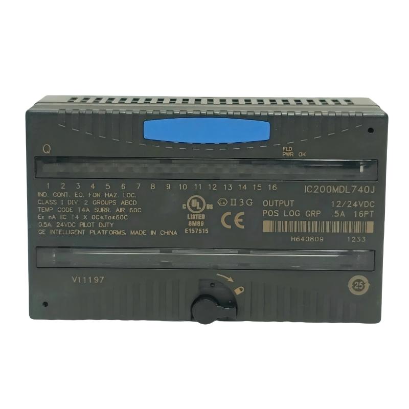
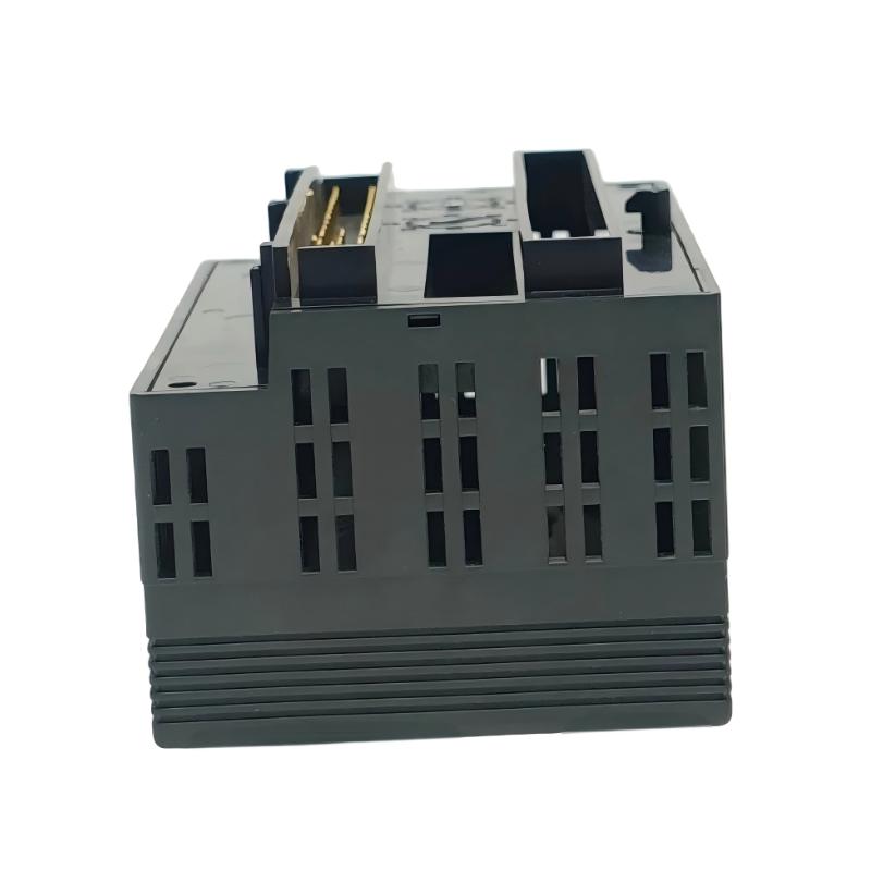
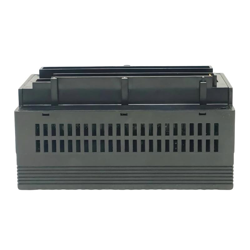
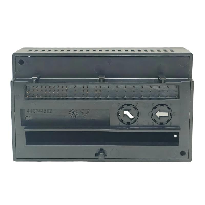
- GE
- IC200MDL740J
- Discrete Output Module
- USA
- 110 × 66.8 × 50 mm
- 0.231 kg
- Xiamen, China
- New & In Stock
- T/T, PayPal, Western Union
- 1 Year
- 1-3 Working Days
- DHL, UPS, TNT, FedEx and EMS.
- 24-Hour Service
- COO
- 50
Our advantage

Global Logistics
We have a 10-year logistics and express cooperation agreement, so our products can be shipped to any place in the world.

Brand new and original
Our products are imported in bulk from the place of origin. Because of the cooperative relationship, our products are all original and 100% new.

24-hour service
We provide 7*24 hours service to our customers. We will be there whenever you need us.

Price advantage
All our products are priced very favorably because we have our own warehouse and supply.
| Company Information | |||
| [email protected] | |||
| Mobile | +8615980777398 | ||
| +8615980777398 | |||
| 15980777398 |
Product Overview
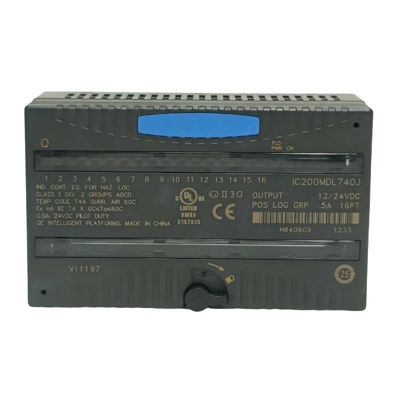
The GE IC200MDL740J VersaMax Discrete Output Module is a digital output component used in GE VersaMax PLC systems to send binary control signals from the controller to field-side devices.
In a machine or process-control cabinet, the PLC continuously makes decisions based on program logic and incoming signals. Some of those decisions need to become physical actions: a motor starter must receive a run command, a solenoid must energize, an indicator must turn on, or a relay must change state. The IC200MDL740J handles this type of discrete output interface.
The module belongs to the output side of the VersaMax I/O architecture. It sits between the PLC’s control logic and the external circuits that execute the commanded action.
A simplified arrangement is:
VersaMax CPU → IC200MDL740J → Output Circuit → Field Device
For example, a conveyor-control application may use one output channel to start a motor-control circuit and another to operate a warning indicator. The PLC program determines when each output should change state, while the output module transfers those states to the corresponding field circuits.
The same concept applies to valves, contactors, relays, solenoids, machine actuators, and other equipment controlled through discrete signals.
When troubleshooting an output that does not produce the expected field action, the module should not automatically be considered the source of the problem. The investigation should also cover the output wiring, terminal assembly, external relay or contactor, protection devices, and the final field device.
Technical Specifications
| Parameter | Specification |
|---|---|
| Manufacturer | GE |
| Model | IC200MDL740J |
| Product Family | VersaMax |
| Product Type | Discrete Output Module |
| Primary Function | Discrete Field Signal Output |
| System Role | PLC Output Interface |
| Application | Industrial Automation / Machine Control |
| Installation | GE VersaMax Control System |
| Dimensions | 110 × 66.8 × 50 mm |
| Weight | 0.231 kg |
Product Features
The IC200MDL740J is used where a VersaMax controller needs to issue defined ON/OFF output commands to external circuits.
- GE VersaMax Discrete Output Module
- Model IC200MDL740J
- Digital field-output interface
- Transfers PLC logic states to external circuits
- Suitable for machine-control applications
- Applicable to relay and contactor control
- Can be used in solenoid and actuator circuits
- Supports equipment start/stop functions
- Suitable for indicator and status-control circuits
- Integrates with VersaMax PLC architectures
- Useful for maintenance and replacement projects
The actual field connection should always be matched with the existing PLC configuration and electrical design.
Working Principle
The IC200MDL740J takes a binary state from the VersaMax control program and makes that state available to the connected output circuit.
The practical path is:
PLC Logic → IC200MDL740J → Terminal / Wiring → External Circuit → Field Device
Suppose a PLC program determines that a conveyor should start.
The controller evaluates the required conditions. Once the start condition is satisfied, the relevant output is commanded to its configured state. The IC200MDL740J transfers this output condition to the connected circuit, which may then operate a relay, contactor, or motor-control interface.
The sequence can be viewed as:
Start Condition → PLC Output Command → IC200MDL740J → Motor-Control Circuit → Conveyor Starts
For a solenoid application, the same process may look like:
Valve Command → IC200MDL740J → Solenoid Circuit → Valve Actuation
The module therefore handles the electrical interface between the PLC program and the external control circuit. The actual process logic remains within the VersaMax controller.
Output Control in a VersaMax System
Discrete output modules are particularly useful where equipment needs clearly defined states rather than continuously variable control.
A typical arrangement may contain several different output functions:
| Output Function | Example Equipment |
|---|---|
| Start | Pump or motor |
| Stop | Motor-control circuit |
| Open | On/off valve |
| Close | Valve actuator |
| Enable | Machine or auxiliary equipment |
| Reset | Drive or control device |
| Alarm | Horn or warning indicator |
| Status | Pilot lamp or external indication |
| Solenoid Command | Pneumatic or hydraulic device |
| Relay Command | External switching circuit |
The IC200MDL740J can therefore participate in both simple machine logic and more involved automated sequences.
Role in a VersaMax PLC Architecture
The module occupies the field-output layer between the VersaMax controller and external equipment.
A simplified architecture is:
Sensors / Inputs → VersaMax CPU → IC200MDL740J → Field Control Circuits → Equipment
| System Element | Function |
|---|---|
| GE IC200MDL740J | Sends discrete output states |
| VersaMax CPU | Executes PLC application logic |
| VersaMax Power Supply | Supports system power requirements |
| I/O Carrier / Interface | Integrates I/O hardware |
| Terminal Assembly | Connects field wiring |
| Relay / Contactor | Switches external equipment circuits |
| Solenoid | Executes a binary actuation command |
| Motor Starter | Controls motor operation |
| Discrete Input Module | Acquires equipment feedback |
| HMI | Displays equipment and process status |
| Field Devices | Perform the commanded action |
A discrete input module can be used alongside the output module when the application needs feedback confirming that the commanded action actually occurred.
Practical Output-Circuit Troubleshooting
A common mistake during maintenance is to assume that an output command and equipment response are the same thing.
They are not.
If the PLC program shows that an output has been commanded, engineers should trace the physical circuit to determine whether the command reaches the final device.
A useful troubleshooting path is:
PLC Logic → IC200MDL740J → Terminal → Field Wiring → Relay / Contactor → Actuator → Equipment
For example, if a motor does not start:
- Check whether the PLC program has issued the start command.
- Confirm the corresponding output channel state.
- Inspect the output connection and terminal assembly.
- Check the field wiring.
- Inspect the relay or contactor.
- Verify the motor-control circuit.
- Check equipment permissives and protection devices.
- Confirm motor-running feedback where available.
This approach prevents unnecessary replacement of the I/O module when the actual fault exists farther downstream.
Industrial Applications
| Application | Typical Use |
|---|---|
| Manufacturing | Machine start/stop control |
| Packaging | Actuator and conveyor commands |
| Material Handling | Motor and conveyor control |
| Water Treatment | Pump and valve operation |
| Process Automation | Equipment sequence control |
| Industrial Machinery | Solenoid and relay control |
| Assembly Systems | Machine actuator commands |
| Building Equipment | Discrete equipment switching |
Installation and Maintenance
Before replacing an IC200MDL740J, the existing output assignment should be documented so that each field circuit can be restored correctly.
Recommended practices include:
- Confirm the complete IC200MDL740J model.
- Verify its position within the VersaMax system.
- Record output-channel assignments.
- Identify the equipment connected to each channel.
- Document existing terminal and field wiring.
- Follow the required electrical isolation procedure.
- Inspect connectors and terminals.
- Check for loose or damaged conductors.
- Inspect external relays and contactors.
- Check solenoid and actuator circuits where applicable.
- Verify the PLC output configuration.
- Inspect the replacement module before installation.
- Install the module according to the approved procedure.
- Restore the field wiring.
- Check PLC and I/O status after power-up.
- Test representative output channels.
- Verify the actual field-device response.
- Confirm feedback signals where available.
- Test relevant machine or process sequences.
- Record the final maintenance condition.
If an output channel appears to operate correctly but the field device does not respond, trace the downstream circuit rather than immediately installing another output module.
Compatible System Components
The IC200MDL740J is normally used together with other VersaMax control and I/O hardware.
| Component | Function |
|---|---|
| GE IC200MDL740J | VersaMax Discrete Output Module |
| GE IC200PWR101B | VersaMax Power Supply Module |
| VersaMax CPU | Executes PLC control logic |
| VersaMax Input Modules | Acquire field conditions |
| VersaMax Analog Modules | Handle process-variable signals |
| I/O Carrier | Provides module interconnection |
| Terminal Assembly | Provides field wiring interface |
| Relay / Contactor | Interfaces external loads |
| Motor Starter | Controls motor circuits |
| Solenoid | Executes discrete commands |
| HMI | Displays machine or process status |
| Field Sensors | Supply process feedback |
Recommended Related Models
| Model / Product Family | Product Type | Typical Application |
|---|---|---|
| GE IC200MDL740J | VersaMax Discrete Output Module | Digital equipment control |
| GE IC200PWR101B | VersaMax Power Supply Module | PLC system power |
| GE IC200PWR102F | VersaMax Power Supply Module | VersaMax power applications |
| GE IC200ALG230D | VersaMax Analog Input Module | Analog signal acquisition |
| GE IC200ALG321B | VersaMax Analog Input Module | Industrial analog inputs |
| GE IC200ALG442B | VersaMax Analog I/O Module | Process signal handling |
| GE VersaMax Discrete Input Modules | VersaMax Discrete Input | Equipment status acquisition |
Key Advantages
- GE VersaMax Discrete Output Module.
- Model IC200MDL740J.
- Transfers PLC logic states to field circuits.
- Suitable for motor, relay, solenoid, and actuator control.
- Supports machine start/stop functions.
- Applicable to automated equipment sequences.
- Can work with discrete feedback inputs.
- Suitable for VersaMax maintenance and replacement applications.
Technical FAQs
What is the IC200MDL740J used for in a VersaMax PLC system?
The IC200MDL740J is used to transfer discrete output commands from the VersaMax control system to external circuits. Typical functions include equipment start/stop, relay switching, solenoid control, actuator commands, and other binary control actions.
What should be checked when the PLC output changes but the equipment does not operate?
Start by confirming the output channel state, then inspect the terminal connection and field wiring. The next checks should include external relays or contactors, protection devices, the actuator or motor-control circuit, and the final equipment. The output module should only be considered faulty after the downstream circuit has been checked.
Why is discrete feedback useful with an output module?
An output tells the PLC what command has been issued, while a feedback input can indicate the actual equipment condition. For example, a motor-start output can be paired with a running-status input. This allows the control program to detect a command that did not produce the expected equipment response.
What information should be recorded before replacing an IC200MDL740J?
Engineers should record the module position, output-channel assignments, connected field devices, terminal connections, and relevant PLC configuration. This information helps ensure that the replacement module is installed into the correct system position and that the existing field circuits are restored properly.