Product Overview
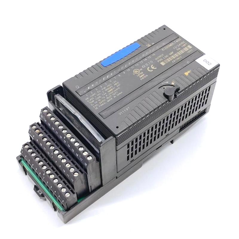
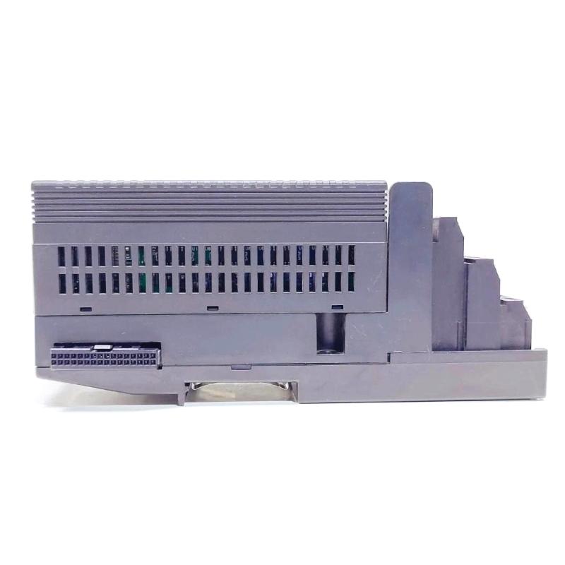
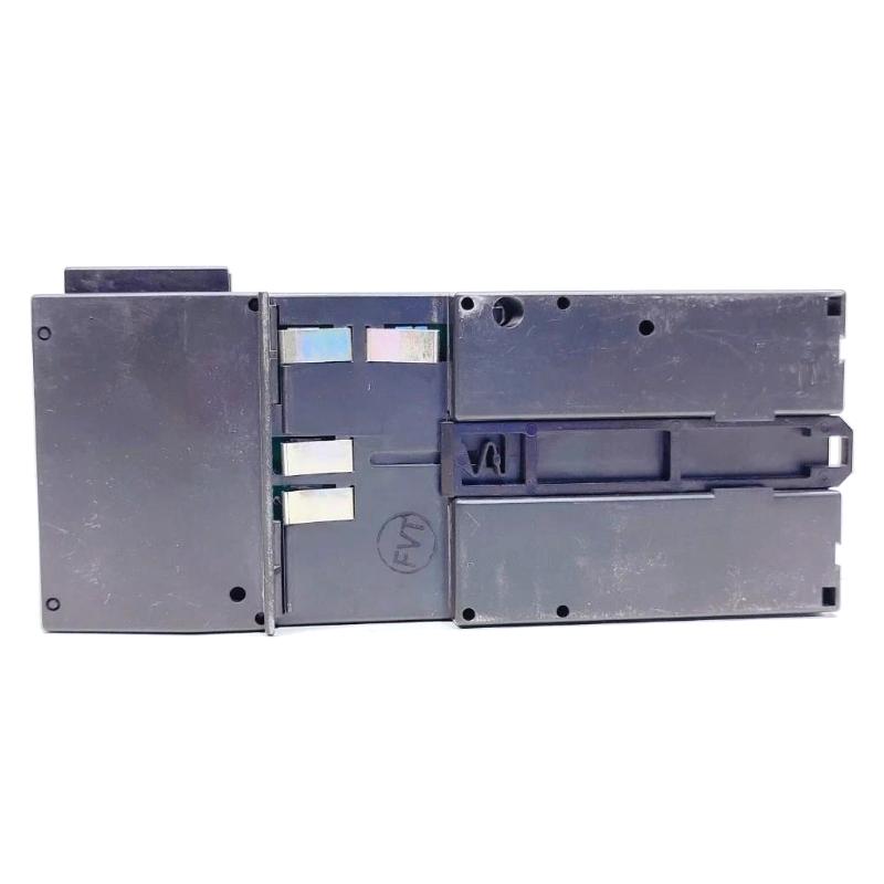
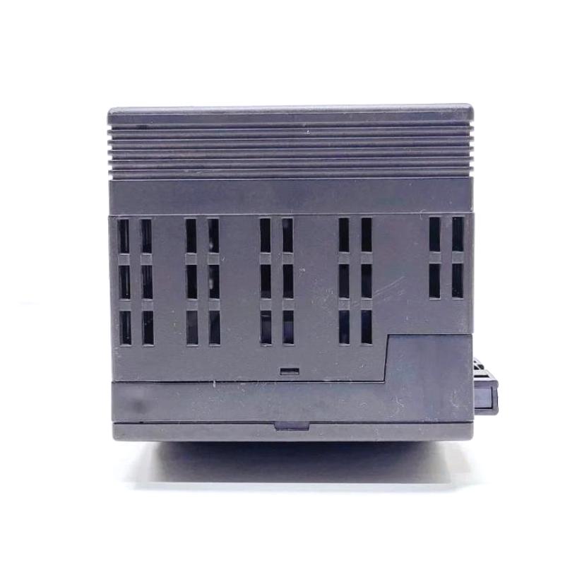
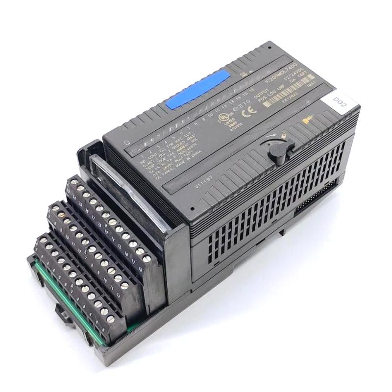
The GE IC200MDL740G VersaMax Discrete Output Module handles the output side of a VersaMax PLC application, sending discrete control states from the controller to external electrical equipment.
In a typical machine, the module can sit between the PLC logic and devices such as contactors, relays, solenoid valves, indicator circuits, motor-control interfaces, and other discrete actuators. When the PLC determines that a machine action should occur, the corresponding output channel changes state and the connected circuit responds.
A packaging machine provides a straightforward example. A product sensor may first confirm that an item is correctly positioned. The PLC then executes the programmed sequence and commands an output associated with a pneumatic solenoid. The IC200MDL740G transfers that discrete command into the field circuit, allowing the actuator to perform the next movement.
The control relationship can be represented as:
PLC Logic → IC200MDL740G → Field Circuit → Actuator / Equipment
The module can also be used in equipment-status sequences where an output command is followed by feedback through a separate input circuit. This allows the PLC to distinguish between command issued and equipment actually reached the expected state.
For replacement work, engineers should check the complete output path rather than treating the module as an isolated component. The output channel, terminal connection, external switching device, field wiring, and controlled load can all affect the final equipment response.
Technical Specifications
| Parameter |
Specification |
| Manufacturer |
GE |
| Model |
IC200MDL740G |
| Product Family |
VersaMax |
| Product Type |
Discrete Output Module |
| Primary Function |
Discrete Field Signal Output |
| System Role |
PLC Output Interface |
| Application |
Industrial Automation / Machine Control |
| Installation |
GE VersaMax Control System |
| Dimensions |
110 × 66.8 × 50 mm |
| Weight |
0.231 kg |
Product Features
- GE VersaMax Discrete Output Module
- Model IC200MDL740G
- Digital output interface for field control
- Suitable for binary equipment commands
- Applicable to relay and contactor control circuits
- Useful for solenoid-operated devices
- Suitable for machine sequence outputs
- Applicable to actuator-control functions
- Supports equipment enable and command signals
- Useful for retrofit and replacement projects
- Integrates with the VersaMax PLC architecture
Working Principle
The IC200MDL740G receives discrete output commands generated by the VersaMax control program and transfers the corresponding electrical state to the connected output circuit.
The practical control path is:
VersaMax CPU → IC200MDL740G → Terminal Connection → External Control Circuit → Equipment
Consider a conveyor application. The PLC receives a product-detection signal through an input module and determines that the conveyor should move. The application logic then commands the appropriate output.
Product Detected → PLC Logic → Output Command → IC200MDL740G → Motor-Control Circuit → Conveyor Operation
A pneumatic application follows a similar pattern:
Sequence Condition Satisfied → PLC Output → IC200MDL740G → Solenoid Circuit → Valve Operation
The output module transfers the commanded discrete state. The external device converts that electrical command into the required mechanical or process action.
When feedback is available, the PLC can separately monitor whether the commanded action actually occurred.
Output Control in a VersaMax System
Discrete outputs are often associated with individual machine functions. The same output architecture can support simple commands as well as multi-step automatic sequences.
| Control Function |
Typical External Device |
| Motor Start Command |
Contactor / Motor Starter |
| Valve Open Command |
Solenoid Valve |
| Valve Close Command |
Solenoid Valve |
| Cylinder Extend |
Pneumatic Solenoid |
| Cylinder Retract |
Pneumatic Solenoid |
| Equipment Enable |
Relay / Control Circuit |
| Alarm Output |
Indicator / Alarm Circuit |
| Machine Release |
Solenoid Actuator |
| Auxiliary Equipment |
Relay-Controlled Device |
| Sequence Command |
External Control Circuit |
The actual field application depends on the machine’s electrical design and the output circuit connected to each channel.
Role in a VersaMax PLC Architecture
The IC200MDL740G occupies the output portion of the VersaMax control architecture.
Input Devices → VersaMax CPU → IC200MDL740G → External Control Circuit → Field Equipment
| System Element |
Function |
| GE IC200MDL740G |
Sends discrete control states |
| VersaMax CPU |
Executes PLC application logic |
| VersaMax Power Supply |
Supports system power requirements |
| VersaMax I/O Carrier |
Provides module interconnection |
| Discrete Input Module |
Acquires field feedback |
| Analog I/O Modules |
Handle continuous process signals |
| Terminal Hardware |
Connects field wiring |
| Relay / Contactor |
Switches external circuits |
| Solenoid Valve |
Controls pneumatic or hydraulic equipment |
| Motor Starter |
Interfaces with motor circuits |
| HMI |
Displays equipment conditions |
The module can work together with discrete input hardware to create a command-and-feedback loop.
PLC Command → Output Module → Equipment → Feedback Device → Input Module → PLC
This arrangement is common in automated machinery where equipment status must be verified before the next operation begins.
Command and Feedback Monitoring
An output changing state confirms that the PLC has issued a command; it does not necessarily confirm that the external equipment completed the requested action.
For example:
IC200MDL740G → Motor Starter → Motor
may be paired with:
Motor Auxiliary Contact → VersaMax Discrete Input → PLC
The PLC can compare the command with the feedback condition. If the expected response does not arrive, the application can identify a potential equipment or field-circuit problem.
This type of arrangement is useful for:
- Motor start confirmation
- Valve-position verification
- Cylinder movement
- Equipment-ready conditions
- Sequence progression
- Machine interlocks
- Fault monitoring
- Actuator-status confirmation
Industrial Applications
| Application |
Typical Use |
| Manufacturing |
Machine start/stop control |
| Packaging |
Solenoid and actuator commands |
| Material Handling |
Conveyor and motor control |
| Assembly Machinery |
Positioning and clamping functions |
| Machine Tools |
Auxiliary equipment control |
| Water Treatment |
Pump and valve commands |
| Process Equipment |
Discrete actuator operation |
| Automated Production Lines |
Sequence-control outputs |
Installation and Maintenance
The output assignment should be documented before replacing the IC200MDL740G, particularly on machines where one module controls several independent devices.
- Confirm the complete IC200MDL740G model.
- Verify its position within the VersaMax system.
- Record output-channel assignments.
- Identify the equipment connected to each channel.
- Document terminal connections.
- Inspect field wiring.
- Check terminals for loose conductors.
- Inspect relays and contactors.
- Check solenoid circuits.
- Verify motor-control interfaces.
- Review the PLC output configuration.
- Follow the approved electrical isolation procedure.
- Install the replacement module.
- Restore field connections.
- Check controller and I/O diagnostics.
- Verify the commanded output state.
- Test representative output channels.
- Confirm the response of connected equipment.
- Check associated feedback inputs.
- Test machine sequences and interlocks.
- Record the completed maintenance configuration.
If a PLC output appears active but the equipment does not respond, inspect the external control circuit before assuming that the IC200MDL740G has failed.
Compatible System Components
| Component |
Function |
| GE IC200MDL740G |
VersaMax Discrete Output Module |
| GE IC200MDL241B |
VersaMax Discrete Input Module |
| GE IC200PWR101B |
VersaMax Power Supply Module |
| GE IC200PWR102F |
VersaMax Power Supply Module |
| VersaMax CPU |
Executes control logic |
| VersaMax I/O Carrier |
Provides module interconnection |
| VersaMax Analog I/O Modules |
Acquire or process analog signals |
| Terminal Assembly |
Provides field wiring connections |
| Relay / Contactor |
Switches external equipment circuits |
| Solenoid Valve |
Operates pneumatic or hydraulic equipment |
| Motor Starter |
Controls motor circuits |
| HMI |
Displays machine and equipment status |
Recommended Related Models
| Model / Product Family |
Product Type |
Typical Application |
| GE IC200MDL740G |
VersaMax Discrete Output Module |
Digital equipment control |
| GE IC200MDL740J |
VersaMax Discrete Output Module |
Digital field output |
| GE IC200MDL241B |
VersaMax Discrete Input Module |
Digital field-state acquisition |
| GE IC200PWR101B |
VersaMax Power Supply Module |
VersaMax system power |
| GE IC200PWR102F |
VersaMax Power Supply Module |
PLC power applications |
| GE IC200ALG230D |
VersaMax Analog Input Module |
Analog process-signal acquisition |
| GE IC200ALG321B |
VersaMax Analog Input Module |
Industrial analog inputs |
Key Advantages
- GE VersaMax Discrete Output Module.
- Model IC200MDL740G.
- Transfers PLC commands to discrete field circuits.
- Suitable for relay, contactor, solenoid, and actuator applications.
- Supports machine sequence control.
- Useful for motor and valve command circuits.
- Can be combined with discrete input feedback.
- Suitable for VersaMax maintenance and replacement work.
Technical FAQs
What is the IC200MDL740G used for in a VersaMax PLC?
The IC200MDL740G is used to send discrete control states from the VersaMax PLC to external equipment. Typical applications include commands associated with relays, contactors, solenoid valves, motors, and machine actuators.
Does an active output prove that the controlled device is operating?
No. An active PLC output indicates that the control system has issued the programmed command. The external relay, contactor, solenoid, wiring, and equipment still need to respond correctly. Feedback through a separate input circuit can be used to confirm the actual equipment state.
What should be checked when a VersaMax output does not operate the connected equipment?
Check the PLC output state first, then inspect the module connection, terminal wiring, external relay or contactor, field circuit, and controlled device. If the output command is present but the load does not respond, the fault may be outside the output module.
Why are discrete output modules commonly used in machine sequencing?
Many machine actions are fundamentally state-based: a valve opens, a motor starts, a cylinder extends, or an actuator returns to its home position. A discrete output can issue these commands while corresponding input signals confirm whether the expected machine condition has been reached.