

ProductPRODUCT
Featured products



Contact Us
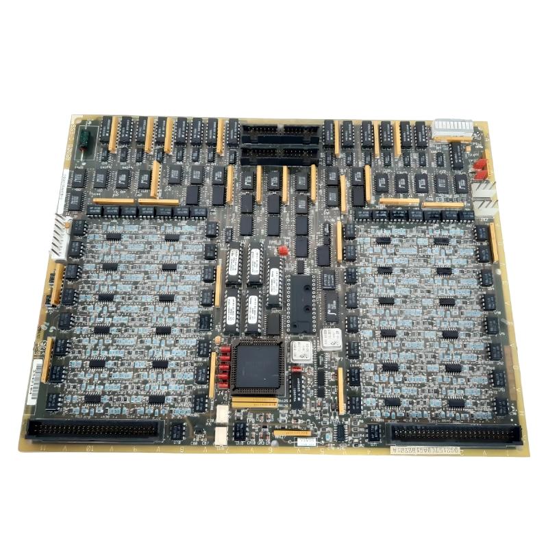
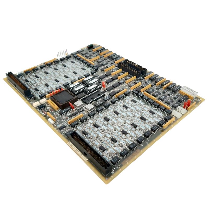
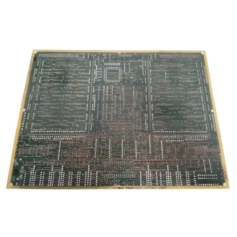
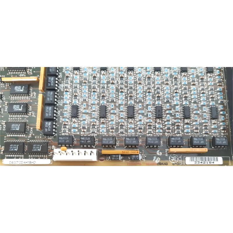
- GE
- DS215TCDAG1BZZ01A
- Printed Circuit Board
- USA
- 265 × 180 × 32 mm
- 0.7 kg
- Xiamen, China
- New & In Stock
- T/T, PayPal, Western Union
- 1 Year
- 1-3 Working Days
- DHL, UPS, TNT, FedEx and EMS.
- 24-Hour Service
- COO
- 53
Our advantage

Global Logistics
We have a 10-year logistics and express cooperation agreement, so our products can be shipped to any place in the world.

Brand new and original
Our products are imported in bulk from the place of origin. Because of the cooperative relationship, our products are all original and 100% new.

24-hour service
We provide 7*24 hours service to our customers. We will be there whenever you need us.

Price advantage
All our products are priced very favorably because we have our own warehouse and supply.
| Company Information | |||
| [email protected] | |||
| Mobile | +8615980777398 | ||
| +8615980777398 | |||
| 15980777398 |
Product Overview
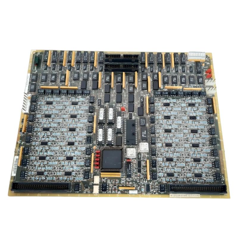
The GE DS215TCDAG1BZZ01A is a specialized Digital I/O Printed Circuit Board designed for compatible GE Mark V turbine control systems. It belongs to the GE Speedtronic control hardware family and is used to process digital field signals and exchange control information with other parts of the turbine control architecture.
The board is commonly identified by its functional board family as the TCDA. In a typical Mark V architecture, the TCDA board provides an interface between field-level contact signals and the main control system. It can receive digital input information from terminal boards and process digital output information associated with turbine control functions.
The DS215TCDAG1BZZ01A is therefore not simply a passive circuit board. It forms an active digital input/output interface within the control system and contains processing, memory, interface, and diagnostic circuitry required for its assigned control functions.
The DS215 identification represents the configured board assembly, while the associated DS200TCDAG1B family identifies the underlying board design. Depending on the exact hardware configuration, different DS200 board revisions or suffixes may be associated with the DS215 assembly. For replacement work, the complete DS215TCDAG1BZZ01A identification should always be checked against the original installed hardware.
With specified dimensions of 265 × 180 × 32 mm and a weight of 0.7 kg, the board is intended for integration into industrial control equipment rather than standalone operation.
Technical Specifications
| Parameter | Details |
|---|---|
| Manufacturer | GE General Electric |
| Model | DS215TCDAG1BZZ01A |
| Functional Board Family | TCDA |
| Associated Board Family | DS200TCDAG1B |
| Product Type | Digital I/O Printed Circuit Board |
| System Family | GE Mark V Speedtronic |
| Primary Function | Digital input and output processing |
| Input Type | Digital / contact input signals |
| Output Type | Digital control output signals |
| Processing | On-board digital signal and I/O processing |
| Memory | On-board memory and programmable logic resources |
| Communication | IONET and associated control-system interfaces |
| Application | Turbine control and industrial automation |
| Installation | Mark V control cabinet / I/O core |
| Dimensions | 265 × 180 × 32 mm |
| Weight | 0.7 kg |
| Construction | Industrial printed circuit board assembly |
| Service Application | Maintenance, replacement and system restoration |
Function and Working Principle
The primary function of the DS215TCDAG1BZZ01A is to process digital input and output information within a compatible GE Mark V control system.
Industrial turbine systems contain many field devices that operate as discrete signals. These devices may indicate whether a valve is open or closed, whether a motor is running, whether a pressure switch has changed state, or whether a protective device has been activated.
The TCDA board provides the electronic interface required to bring these digital signals into the control system and distribute digital output commands to the appropriate field equipment.
A simplified digital input path can be represented as:
Field Contact / Switch → Terminal Board → TCDA Board → I/O Processing → Control Network → Main Controller
For digital output functions, the direction is reversed:
Main Controller → Control Network → TCDA Board → Output Interface → Terminal Board → Field Device
This two-way operation allows the board to participate in both monitoring and control functions.
The board can therefore handle information associated with:
- Limit switches
- Pressure switches
- Temperature switch contacts
- Valve position indications
- Motor status signals
- Relay contact information
- Equipment permissive signals
- Protection signals
- Digital control commands
- Alarm and status outputs
Because these signals can be used by turbine protection and control logic, reliable digital I/O operation is essential to the overall control system.
Role in Industrial Control Systems
The GE DS215TCDAG1BZZ01A plays an important role as an interface between field equipment and the Mark V control architecture.
A turbine control system must continuously collect information from switches, relays, valves, protection devices, and other discrete field equipment. The control processor then uses this information to determine equipment status and execute control logic.
The TCDA board provides the digital interface required to move this information between the field and the control processors.
Within a typical system, the board can work alongside:
- GE Mark V control processors
- DTBA terminal boards
- DTBB terminal boards
- TCQC control boards
- TCRA relay output boards
- IONET communication interfaces
- TCPS power supply boards
- Other Mark V I/O boards
- Field switches and relay contacts
- Industrial valves and actuators
The board’s position in the signal chain makes it important for both normal operation and fault diagnosis.
For example, if a valve-position signal is not received by the controller, the problem could originate at the field switch, terminal board, wiring, TCDA input channel, communication path, or control processor. The TCDA should therefore always be evaluated as part of the complete signal path.
Industrial Applications
The GE DS215TCDAG1BZZ01A is associated primarily with GE Mark V Speedtronic turbine control systems and other compatible industrial automation environments.
Typical application areas include:
- Gas turbine control systems
- Steam turbine control systems
- Power generation plants
- Industrial turbine installations
- Generator auxiliary systems
- Industrial process equipment
- Combustion control systems
- Turbine protection and monitoring systems
- Legacy GE Speedtronic installations
In power-generation applications, digital I/O information is essential for monitoring equipment state and executing discrete control commands.
Examples include monitoring whether a valve has reached its commanded position, determining whether an auxiliary motor is running, detecting a protective relay condition, or sending a control command to a relay output circuit.
The board therefore supports the basic communication between the physical equipment and the digital control logic running in the Mark V system.
Digital Input Function
One of the major functions of the DS215TCDAG1BZZ01A is digital input processing.
Digital input signals generally represent two-state information. Depending on the application, the state can represent conditions such as ON/OFF, OPEN/CLOSED, RUN/STOP, HEALTHY/FAULT, or ENABLE/DISABLE.
The board receives these signals through the associated terminal and interface hardware. The input circuitry processes the signal and passes the resulting digital state into the control system.
Typical digital inputs can include:
- Valve limit switches
- Pressure switch contacts
- Relay status contacts
- Motor running indications
- Breaker status
- Equipment permissives
- Trip indications
- Alarm contacts
- Auxiliary equipment status
The control system can then use these states in sequencing, permissive logic, alarm generation, and protection functions.
Digital Output Function
In addition to digital input processing, the TCDA architecture can participate in digital output functions.
A digital output command originates in the control logic. The command is transmitted through the control system to the appropriate I/O hardware and then delivered to the external interface or terminal board.
The output may ultimately operate a relay, solenoid, contactor, or other discrete control device.
Typical applications include:
- Relay control
- Valve control commands
- Solenoid operation
- Auxiliary motor commands
- Alarm outputs
- Equipment permissive signals
- Control-system status outputs
This output capability allows the Mark V controller to interact directly with the physical turbine system.
IONET Communication
The DS215TCDAG1BZZ01A can communicate with the wider Mark V control architecture through the system’s I/O communication network.
IONET provides the communication path between the I/O boards and control-system hardware. The TCDA uses this communication architecture to exchange digital input and output information with the appropriate control components.
The communication process can be summarized as:
TCDA Digital I/O Processing → IONET → Mark V Control Processor
For output operations, the information travels in the opposite direction:
Mark V Control Logic → IONET → TCDA → Field Output Interface
This architecture separates field signal wiring from the main control processing hardware while maintaining a structured communication path between them.
Compatible System Components
The DS215TCDAG1BZZ01A operates as part of a larger Mark V I/O architecture. Several related boards and components can be used alongside the TCDA depending on the turbine configuration.
| Component | Type | Function |
|---|---|---|
| DS200TCDAG1B | Digital I/O Board | Underlying TCDA digital I/O board family |
| DTBA | Terminal Board | Provides field digital signal connections |
| DTBB | Terminal Board | Interfaces field contact inputs and related signals |
| TCQC | Control Board | Processes and communicates control information |
| TCRA | Relay Output Board | Handles relay output functions |
| TCPS | Power Supply Board | Provides control-system power |
| IONET Hardware | Communication Interface | Transfers I/O information within the Mark V system |
| Field Switches | Digital Input Devices | Provide discrete equipment status information |
| Relays and Solenoids | Output Devices | Execute digital control commands |
These components form a complete signal chain between field equipment and the turbine control processor.
Board Hardware and Interface Design
The DS215TCDAG1BZZ01A contains active electronic circuitry used for digital I/O processing and communication. The underlying TCDA board family can include a microprocessor, programmable memory devices, status indicators, connectors, and configuration hardware.
Its physical interfaces are important because different connectors can serve different functions.
Depending on the specific configuration, the board interfaces can be associated with:
- System power
- IONET communication
- Digital field signal connections
- Relay or output information
- Inter-board communication
- Configuration and diagnostic functions
Technicians should always document connector positions before removing the original board. Similar-looking connectors should not be assumed to have the same electrical function.
Installation and System Integration
Proper installation is important because the DS215TCDAG1BZZ01A is connected to both field-level signals and the Mark V control network.
A recommended installation procedure includes:
- Place the turbine control system in the approved maintenance state.
- Isolate electrical power according to the equipment safety procedure.
- Verify that the control cabinet is safe to access.
- Record the complete DS215TCDAG1BZZ01A identification.
- Record the associated DS200TCDAG1B board information.
- Document all cable and connector locations.
- Record jumper and configuration positions.
- Inspect the replacement board for physical damage.
- Check connectors for bent contacts, corrosion, or contamination.
- Install the board in the correct Mark V I/O location.
- Reconnect the IONET and field interface connections.
- Verify that all connectors are fully seated.
- Check the board mounting and grounding arrangement.
- Restore power according to the approved procedure.
- Check board status indicators.
- Verify digital input status.
- Verify digital output operation under controlled conditions.
- Confirm communication with the Mark V control system.
Electrostatic discharge protection should be used whenever the PCB is handled. The board should be stored and transported in suitable anti-static packaging.
After installation, technicians should verify the complete signal path rather than checking only whether the board powers up.
Maintenance and Troubleshooting Considerations
Troubleshooting the DS215TCDAG1BZZ01A requires a systematic approach because a digital I/O fault can originate from many different points in the signal chain.
| Observed Condition | Possible Area to Check |
|---|---|
| Digital input remains OFF | Field switch, wiring, terminal board, input channel and TCDA connection |
| Digital input remains ON | Field contact, wiring short, input circuit and configuration |
| Several inputs fail simultaneously | Power, common wiring, terminal board or TCDA hardware |
| Digital output does not operate | Control logic, IONET communication, TCDA output and terminal interface |
| Intermittent I/O signal | Loose connector, wiring, vibration, terminal connection or PCB condition |
| IONET communication fault | Network cable, connectors, communication hardware and TCDA interface |
| Board does not initialize | Power supply, configuration memory, board hardware and communication path |
| Incorrect I/O status | Configuration, field wiring, input polarity and control logic |
When only one digital input is affected, technicians should first inspect the corresponding field device and wiring. A single-channel fault does not necessarily indicate a complete board failure.
If many channels fail simultaneously, common power, communication, or board-level problems should be considered.
Similarly, if digital outputs cannot be activated, the control command should first be verified. The problem may exist in the control logic or IONET communication rather than in the output hardware.
Diagnostic Indicators
Status LEDs can provide useful information during troubleshooting. The TCDA board architecture can use indicator LEDs to show board or channel-related status.
When diagnosing a problem, technicians should observe the board indicators together with the system diagnostic information.
Useful observations include:
- Power indication
- Board status
- Communication activity
- I/O state indication
- Abnormal LED patterns
- Changes during system startup
LED information should not be interpreted independently. A complete diagnosis should compare the observed LED status with the expected system state and field measurements.
Firmware and Configuration Considerations
The DS215TCDAG1BZZ01A can be associated with firmware or configuration information specific to the Mark V application.
This is an important consideration when replacing the board. Two boards with similar hardware design may not necessarily contain identical application information.
Before replacement, technicians should document:
- Complete board part number
- Hardware revision
- Firmware identification
- Memory device arrangement
- Jumper settings
- Connector configuration
- System core location
Matching these parameters helps reduce the possibility of configuration-related problems after installation.
Role in Mark V Redundant Control Architecture
GE Mark V systems can use redundant or multiple control paths depending on the specific turbine configuration. Digital I/O information may therefore be processed through more than one control channel or associated I/O core.
The TCDA board can be installed within designated I/O cores where it exchanges information with terminal boards and control processors.
This architecture improves system availability by separating control functions and providing structured signal paths.
For maintenance personnel, it is important to identify the exact core and board position before replacement. Installing a correctly identified board into the wrong system location can create configuration or communication problems.
Recommended Alternative Models
The following models are related to the GE Mark V control and I/O ecosystem and may be useful for comparison or spare-parts planning. They should not automatically be considered direct replacements for the DS215TCDAG1BZZ01A.
| Model | Type | Key Feature | Application |
|---|---|---|---|
| DS215TCDAG1BZZ01A | Digital I/O Board | TCDA digital input/output processing | GE Mark V turbine control |
| DS200TCDAG1B | Digital I/O Board | Underlying TCDA board family | GE Mark V I/O systems |
| DS200TCDAG1BCB | Digital I/O Board | TCDA board configuration | Mark V turbine control |
| DS200TCDAG1BDB | Digital I/O Board | Related TCDA hardware configuration | GE Mark V digital I/O |
| DS215TCEAG1BZZ01A | Digital I/O Board | Related Mark V I/O architecture | GE turbine control systems |
| DS215TCQAG1BZZ01A | Control / I/O Board | Related Mark V control interface | GE Speedtronic systems |
| DS215TCQBG1BZZ01A | Control / I/O Board | Related control-system processing | GE Mark V installations |
Replacement recommendation: The DS215TCDAG1BZZ01A should preferably be matched using the complete part number and installed configuration. Related DS200TCDAG1B variants can have different hardware revisions, firmware, memory arrangements, or I/O configurations, so functional similarity alone should not be used as the final replacement criterion.
Key Advantages
- Designed for GE Mark V turbine control architecture
- Provides digital input and output processing
- Interfaces field contact signals with the control system
- Supports communication with the Mark V control network
- Supports turbine status and alarm monitoring
- Can participate in digital control commands
- Provides active processing rather than passive signal routing
- Suitable for legacy GE Speedtronic installations
- Useful for maintenance and replacement of existing Mark V systems
- Supports integration between field devices and control processors
Technical FAQs
What is the GE DS215TCDAG1BZZ01A?
The GE DS215TCDAG1BZZ01A is a Digital I/O Printed Circuit Board used in compatible GE Mark V Speedtronic turbine control systems. It belongs to the TCDA functional board family.
What is the main function of the DS215TCDAG1BZZ01A?
Its primary function is to process digital input and output information between field devices, terminal boards, and the Mark V control system.
What does TCDA mean?
TCDA identifies the functional board family associated with digital I/O processing in the Mark V control architecture.
What are the dimensions of the DS215TCDAG1BZZ01A?
The specified dimensions are 265 × 180 × 32 mm.
How much does the DS215TCDAG1BZZ01A weigh?
The specified weight is 0.7 kg.
Where is the DS215TCDAG1BZZ01A used?
It is associated with GE Mark V Speedtronic turbine control systems, particularly applications requiring digital field input and output processing.
Is the DS215TCDAG1BZZ01A an input board or an output board?
It is a Digital I/O Board, meaning that its architecture supports both digital input and digital output functions within the compatible control system.
What is the relationship between DS215TCDAG1BZZ01A and DS200TCDAG1B?
DS215TCDAG1BZZ01A identifies the configured DS215-series assembly, while DS200TCDAG1B identifies the associated underlying TCDA board family. The exact revision and hardware configuration should be checked before replacement.
What components work with the DS215TCDAG1BZZ01A?
Associated components can include DTBA and DTBB terminal boards, TCQC control hardware, TCRA relay output boards, TCPS power supplies, IONET communication hardware, field switches, relays, solenoids, and other Mark V I/O components.
What should be checked before replacing the TCDA board?
The complete part number, hardware revision, firmware, memory devices, jumper settings, connector positions, I/O core location, and associated terminal-board wiring should be checked before replacement.
Can a similar DS200TCDAG1B board be used as a direct replacement?
Not automatically. Different DS200TCDAG1B revisions may have different configuration details. The replacement should be matched to the complete installed system configuration.
Conclusion
The GE DS215TCDAG1BZZ01A Digital I/O Printed Circuit Board is an important interface component within compatible GE Mark V Speedtronic turbine control systems. As part of the TCDA board family, it provides digital input and output processing between field equipment and the central control architecture.
The board can receive discrete status information from switches, relays, valves, motors, and protection devices while also participating in digital output commands used to control external equipment. Through its communication interface with the Mark V system, the TCDA provides an important connection between field-level signals and turbine control logic.
With specified dimensions of 265 × 180 × 32 mm and a weight of 0.7 kg, the DS215TCDAG1BZZ01A is designed for integration into industrial control cabinets and Mark V I/O cores. Its active processing, memory, communication, and diagnostic functions make it more than a simple terminal interface.
For maintenance engineers and industrial automation specialists, accurate identification is essential when replacing this legacy GE board. The complete DS215TCDAG1BZZ01A configuration should be compared with the original board, including its hardware revision, firmware, memory arrangement, jumper settings, connector configuration, and I/O location.
When correctly installed and integrated with the appropriate terminal boards, communication hardware, control processors, and field devices, the DS215TCDAG1BZZ01A provides a reliable digital I/O interface for established GE Mark V turbine control applications. Proper installation, signal verification, and systematic troubleshooting are essential for maintaining stable operation of the overall control system.