

ProductPRODUCT
Featured products



Contact Us
- GE
- DS215TCDAG1BZZ01A DS200TCDAG1BDB
- Printed Circuit Board
- USA
- 265 × 180 × 32 mm
- 0.7 kg
- Xiamen, China
- New & In Stock
- T/T, PayPal, Western Union
- 1 Year
- 1-3 Working Days
- DHL, UPS, TNT, FedEx and EMS.
- 24-Hour Service
- COO
- 55
Our advantage

Global Logistics
We have a 10-year logistics and express cooperation agreement, so our products can be shipped to any place in the world.

Brand new and original
Our products are imported in bulk from the place of origin. Because of the cooperative relationship, our products are all original and 100% new.

24-hour service
We provide 7*24 hours service to our customers. We will be there whenever you need us.

Price advantage
All our products are priced very favorably because we have our own warehouse and supply.
| Company Information | |||
| [email protected] | |||
| Mobile | +8615980777398 | ||
| +8615980777398 | |||
| 15980777398 |
Product Overview
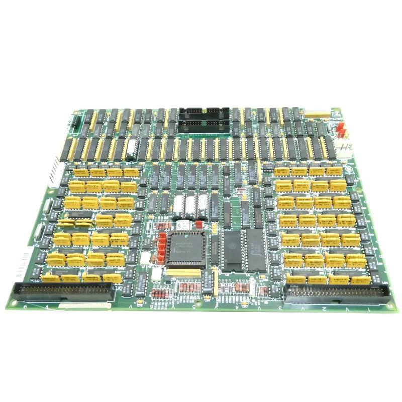
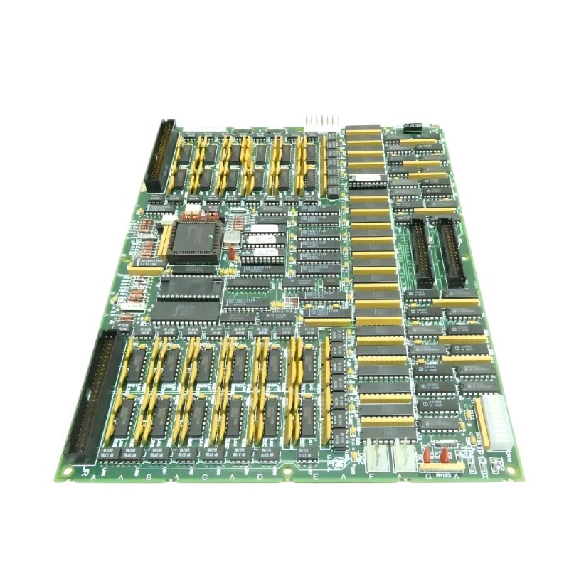
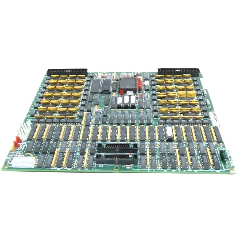
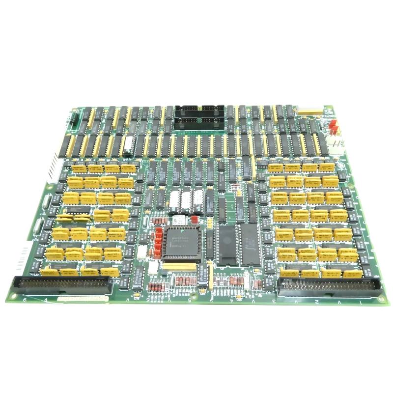
The GE DS215TCDAG1BZZ01A with the associated DS200TCDAG1BDB is a Digital I/O Printed Circuit Board designed for compatible GE Mark V Speedtronic turbine control systems. The board belongs to the TCDA family and provides an important interface between field-level digital signals and the control architecture.
In an industrial turbine control system, digital information is required to continuously monitor equipment status and execute discrete control commands. Signals from switches, relays, valves, auxiliary equipment, protection circuits, and other field devices must be transferred reliably to the control processors. The TCDA board provides the electronic processing and interface functions required for this purpose.
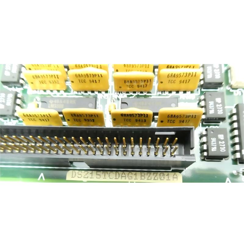
The DS215TCDAG1BZZ01A identifies the configured DS215-series assembly, while DS200TCDAG1BDB identifies the associated TCDA Digital I/O board configuration. These two identifiers are important when selecting replacement hardware for an existing Mark V installation.
The board is designed to handle digital input and output functions within the turbine control architecture. It can receive discrete contact information through associated terminal boards, process the information, and communicate the resulting status to the Mark V control system. It can also participate in output functions where control commands are transferred toward relays, solenoids, valves, and other discrete field devices.
Because it contains active electronic processing and communication circuitry, the DS215TCDAG1BZZ01A is more than a simple passive printed circuit board. It forms part of the active I/O processing layer of the control system.
The specified physical dimensions of this product configuration are 265 × 180 × 32 mm, with a specified weight of 0.7 kg.
Technical Specifications
| Parameter | Details |
|---|---|
| Manufacturer | GE General Electric |
| Model | DS215TCDAG1BZZ01A |
| Associated Board | DS200TCDAG1BDB |
| Functional Board Family | TCDA |
| Product Type | Digital I/O Printed Circuit Board |
| System Family | GE Mark V Speedtronic |
| Primary Function | Digital input and output processing |
| Input Function | Digital contact and status signal processing |
| Output Function | Discrete control and relay output interfacing |
| Signal Type | Digital / discrete signals |
| Communication | Mark V I/O communication architecture |
| Associated Terminal Hardware | DTBA / DTBB and compatible Mark V terminal boards |
| Installation | Mark V control cabinet / I/O core |
| Application | Turbine control and industrial automation |
| Dimensions | 265 × 180 × 32 mm |
| Weight | 0.7 kg |
| Board Designation | TCDA Digital I/O |
| Service Application | Maintenance, replacement and system restoration |
Function and Working Principle
The main function of the DS215TCDAG1BZZ01A DS200TCDAG1BDB is to process digital field information and exchange it with the GE Mark V turbine control system.
Digital signals are commonly used in turbine automation because many physical conditions can be represented by discrete states. For example, a valve may be open or closed, a motor may be running or stopped, a breaker may be open or closed, and a protection contact may indicate either normal or fault status.
The TCDA board receives these signals through the associated I/O interface and processes them so that they can be used by the Mark V control logic.
A simplified digital input signal path can be represented as:
Field Device → Field Wiring → Terminal Board → TCDA Board → I/O Processing → Mark V Network → Control Processor
For output operation, the signal path is reversed:
Mark V Control Processor → I/O Network → TCDA Board → Output Interface → Terminal Board → Field Device
This two-way interface allows the turbine control system to monitor physical equipment while also issuing discrete commands.
The board can therefore participate in functions involving:
- Valve open and closed feedback
- Motor running status
- Motor stopped status
- Breaker status
- Relay contact monitoring
- Pressure switch signals
- Limit switch signals
- Equipment permissive signals
- Alarm contacts
- Protection indications
- Trip-related discrete signals
- Solenoid control
- Relay output commands
Reliable processing of these signals is essential because many turbine sequences depend on correct digital feedback. A controller may require confirmation that a valve has reached the requested position before continuing with another operation. Similarly, an auxiliary motor may need to be confirmed as running before a subsequent control sequence is permitted.
Role in Industrial Control Systems
The GE DS215TCDAG1BZZ01A plays an important role in the I/O architecture of compatible Mark V turbine control systems.
A turbine installation can contain a large number of discrete signals. These signals may originate from field switches, relay contacts, valves, motors, circuit breakers, protection systems, and auxiliary equipment.
The control processor requires an organized method for receiving this information. The TCDA board provides part of this interface by processing digital field information and exchanging it with the control architecture.
Depending on the specific Mark V configuration, the board can operate alongside:
- GE Mark V control processors
- DTBA terminal boards
- DTBB terminal boards
- TCRA relay output boards
- TCQA control boards
- TCQE control boards
- TCEA interface boards
- STCA interface hardware
- TCPS power supply boards
- Mark V I/O communication hardware
- Field switches and relays
- Valves and solenoids
The TCDA board is particularly important because it forms a processing point between field-level electrical signals and higher-level control logic.
For maintenance purposes, this means that an apparent control-system fault may not necessarily originate inside the board. A faulty field switch, loose terminal connection, damaged cable, incorrect configuration, or communication problem can produce symptoms that look like a TCDA failure.
A systematic troubleshooting method is therefore recommended whenever abnormal digital I/O behavior is observed.
Digital Input Function
Digital input processing is one of the principal functions associated with the DS200TCDAG1BDB.
Field equipment can provide discrete contact signals representing different operating states. These signals are routed through terminal hardware and then presented to the I/O board.
Examples of digital input information include:
- Valve position feedback
- Motor running feedback
- Motor fault feedback
- Breaker position
- Relay state
- Pressure switch state
- Limit switch state
- Equipment permissive status
- Protection status
- Auxiliary equipment status
The TCDA board processes these discrete conditions and makes the corresponding information available to the Mark V control system.
This information can then be used for alarm generation, sequence control, permissive logic, interlocking, equipment monitoring, and other control functions.
For example, if a valve is commanded to open, the controller may require a digital feedback signal confirming the open position. If the expected feedback does not arrive, the control system can identify an abnormal condition and prevent the next sequence from proceeding.
Digital Output Function
The board also participates in digital output functions within the Mark V architecture.
A digital output command is generated by control logic and transmitted through the I/O communication architecture. The TCDA board receives the relevant command and interfaces it with the associated output circuitry.
Typical output applications include:
- Relay activation
- Solenoid control
- Valve commands
- Auxiliary equipment commands
- Discrete enable signals
- Alarm outputs
- Equipment permissive outputs
Digital outputs provide the connection between software-based control decisions and physical equipment.
For example, a Mark V control sequence may issue a command to energize a solenoid. The command is processed through the control system and I/O architecture, and the appropriate output circuit is activated.
The correct operation of this path depends on the controller, communication network, TCDA board, terminal hardware, wiring, and field device all operating correctly.
Mark V Communication Architecture
The DS215TCDAG1BZZ01A operates within the communication architecture of the GE Mark V control system.
Digital I/O information must be transferred between the I/O hardware and control processors. The Mark V communication architecture provides the path for this exchange.
The general signal flow can be represented as:
Field Input → Terminal Board → TCDA → I/O Communication → Control Processor
For output control:
Control Processor → I/O Communication → TCDA → Terminal Board → Field Output
This arrangement separates field wiring from the main control-processing hardware while maintaining a structured data path.
When a communication problem occurs, several I/O channels can potentially be affected at the same time. Therefore, simultaneous loss of multiple digital signals should prompt technicians to inspect common communication and power paths rather than immediately replacing several field devices.
Industrial Applications
The DS215TCDAG1BZZ01A DS200TCDAG1BDB is primarily associated with GE Mark V Speedtronic turbine control systems.
Typical industrial applications include:
- Gas turbine control
- Steam turbine control
- Power generation systems
- Industrial turbine installations
- Combined-cycle power plants
- Generator auxiliary systems
- Turbine protection systems
- Industrial process control
- Legacy GE Speedtronic installations
In these applications, the board can support the monitoring of equipment states and the execution of discrete commands.
For example, turbine auxiliary equipment may provide running-status signals to the control system, while the control system can send relay or solenoid commands to field equipment. The TCDA board provides an important part of this interface.
Its role becomes particularly important in systems where large numbers of discrete signals must be processed continuously and reliably.
Compatible System Components
The DS215TCDAG1BZZ01A is normally integrated with multiple components rather than operating as a standalone device.
| Component | Type | Function |
|---|---|---|
| DS200TCDAG1BDB | Digital I/O Board | Associated TCDA board configuration |
| DTBA | Terminal Board | Field signal termination and interface |
| DTBB | Terminal Board | Digital field input interface |
| TCRA | Relay Output Board | Relay and discrete output functions |
| TCQA | Control Board | Mark V control processing and interface |
| TCQE | Control Board | Related turbine control functions |
| TCEA | Interface Board | System interface functions |
| STCA | Interface Board | Mark V system interface |
| TCPS | Power Supply Board | Control-system power distribution |
| I/O Network Hardware | Communication Interface | Transfers I/O information |
| Field Switches | Digital Input Devices | Provide equipment status |
| Relays / Solenoids | Output Devices | Execute discrete commands |
The actual combination of components depends on the specific Mark V installation and turbine configuration.
Installation and System Integration
Correct installation is essential for reliable operation of the DS215TCDAG1BZZ01A because the board is connected to both the control communication system and field I/O hardware.
Before installation, the complete identification of the existing board should be recorded.
A recommended installation sequence includes:
- Place the turbine control system in the approved maintenance state.
- Follow the site’s electrical isolation and lockout procedures.
- Verify that the relevant power has been removed.
- Record the complete DS215TCDAG1BZZ01A part number.
- Record the DS200TCDAG1BDB identification.
- Document the board location and I/O core position.
- Record all connector positions.
- Record jumper and configuration settings.
- Inspect the replacement PCB for physical damage.
- Check connectors and pins before installation.
- Install the board in the correct rack or I/O position.
- Reconnect all communication connections.
- Reconnect field interface connections.
- Verify that each connector is fully seated.
- Check board mounting and grounding.
- Restore power according to the approved procedure.
- Observe board initialization and status indicators.
- Verify communication with the control system.
- Check digital input states.
- Perform controlled output testing.
- Confirm normal system operation.
Electrostatic discharge precautions should be used when handling the printed circuit board. The PCB should be handled by its edges and protected from conductive surfaces and static discharge.
After installation, technicians should verify actual I/O operation instead of relying solely on board power indicators.
Hardware Configuration
The DS200TCDAG1BDB configuration can include hardware resources that influence its operation within the Mark V system.
Configuration information may be associated with jumpers, memory devices, programmable logic, board revision, and other hardware characteristics.
Before replacing the board, maintenance personnel should document:
- Complete board identification
- Hardware revision
- Jumper settings
- Memory device arrangement
- Firmware or programmable logic information
- Connector arrangement
- I/O core location
- Associated terminal board
This information is particularly important when replacing legacy control-system hardware because boards from the same functional family may have different configurations.
A board that appears physically similar may not necessarily be electrically or functionally identical to the installed version.
Maintenance and Troubleshooting
Troubleshooting the DS215TCDAG1BZZ01A DS200TCDAG1BDB should begin with the complete signal path rather than immediately assuming that the PCB is defective.
| Observed Condition | Possible Area to Check |
|---|---|
| One digital input is missing | Field switch, wiring, terminal connection and input channel |
| Several digital inputs fail simultaneously | Power, terminal board, communication or TCDA hardware |
| Input remains permanently active | Field contact, wiring short, input circuit or configuration |
| Input remains permanently inactive | Field device, wiring, terminal hardware or input circuit |
| Digital output does not operate | Control command, communication, output circuit or terminal hardware |
| Several outputs fail together | Common power, communication or board-level problem |
| Intermittent I/O operation | Connector, wiring, vibration, contamination or PCB condition |
| Communication fault | I/O network, connectors, board power or communication circuitry |
| Board fails to initialize | Power, configuration, memory or hardware problem |
If only one input channel is affected, technicians should inspect the corresponding field device and terminal connection first.
If multiple channels fail at the same time, common power, communication, terminal-board, or board-level causes become more likely.
Intermittent problems should be investigated carefully because vibration, loose connectors, aging wiring, thermal cycling, and contamination can all create unstable signal conditions.
Diagnostic Indicators
Board status indicators can provide useful information during troubleshooting.
During startup and operation, technicians can observe:
- Power status
- Board initialization
- Communication activity
- I/O activity
- Abnormal LED conditions
- Changes in status during field-device operation
However, LED indications should be considered together with control-system diagnostics and field measurements. A normal power indication does not prove that every I/O channel is functioning correctly.
A complete diagnostic process should compare the expected control-system state with actual field conditions and measured electrical signals.
Common Failure Causes
Several conditions can contribute to digital I/O problems in a legacy Mark V installation.
- Loose terminal connections
- Damaged field wiring
- Faulty switches
- Relay contact problems
- Communication cable problems
- Power supply interruptions
- Incorrect jumper configuration
- Configuration mismatch
- PCB component aging
- Connector contamination
- Thermal stress
- Mechanical vibration
- Improper board installation
Because these faults can produce similar symptoms, technicians should isolate the problem systematically.
For example, if a valve-position indication is missing, the investigation should proceed from the valve limit switch through the field wiring and terminal board to the TCDA input and finally to the control-system display.
Replacement and Compatibility Considerations
When sourcing a replacement for the GE DS215TCDAG1BZZ01A DS200TCDAG1BDB, the complete identification should be checked.
Important information includes:
- DS215TCDAG1BZZ01A
- DS200TCDAG1BDB
- TCDA board family
- Hardware revision
- Firmware configuration
- Memory configuration
- Jumper arrangement
- Connector arrangement
- System I/O core position
The associated terminal hardware should also be identified before installing a replacement board.
Related TCDA models may appear similar and may have compatible functions, but differences in board revision or configuration can affect system behavior. Therefore, the closest complete part-number match is generally preferred for maintenance and spare-parts planning.
Recommended Alternative Models
The following models belong to the related GE Mark V I/O and control hardware family. They can be considered for comparison or spare-parts planning, but they should not be treated as automatic direct replacements without verifying the complete system configuration.
| Model | Type | Key Feature | Application |
|---|---|---|---|
| DS215TCDAG1BZZ01A | Digital I/O Board | Configured TCDA assembly | GE Mark V turbine control |
| DS200TCDAG1BDB | Digital I/O Board | TCDA digital I/O processing | Mark V Speedtronic systems |
| DS200TCDAG1BCB | Digital I/O Board | Related TCDA configuration | GE Mark V digital I/O |
| DS200TCDAG1B | Digital I/O Board | Base TCDA board family | Mark V I/O applications |
| DS200TCDAG1BFD | Digital I/O Board | Related TCDA hardware configuration | GE turbine control |
| DS215TCEAG1BZZ01A | Digital I/O Board | Related Mark V I/O architecture | GE Speedtronic systems |
| DS215TCQAG1BZZ01A | Control / I/O Board | Related control-system processing | GE Mark V installations |
Replacement recommendation: The complete DS215TCDAG1BZZ01A DS200TCDAG1BDB identification should be used when matching replacement hardware. Other TCDA variants should be evaluated for hardware revision, firmware, memory configuration, jumper settings, and system compatibility before installation.
Key Advantages
- Designed for compatible GE Mark V Speedtronic turbine control systems
- Provides digital input and output processing
- Interfaces field status signals with the control system
- Supports discrete equipment monitoring
- Supports relay and solenoid control functions
- Works within the Mark V I/O communication architecture
- Provides an active interface between terminal hardware and control processors
- Suitable for legacy turbine control maintenance
- Useful for industrial automation spare-parts planning
- Supports reliable transfer of digital control information
Technical FAQs
What is the GE DS215TCDAG1BZZ01A?
The GE DS215TCDAG1BZZ01A is a configured Digital I/O Printed Circuit Board associated with the GE Mark V Speedtronic turbine control architecture. The corresponding board identification is DS200TCDAG1BDB.
What is the main function of the DS200TCDAG1BDB?
The DS200TCDAG1BDB provides digital input and output processing between field-level equipment and the Mark V control system.
What does the TCDA board do?
The TCDA board processes discrete field signals and exchanges digital I/O information with the Mark V control architecture. It can support both monitoring and discrete control functions.
What are the dimensions of the DS215TCDAG1BZZ01A?
The specified dimensions are 265 × 180 × 32 mm.
What is the weight of the DS215TCDAG1BZZ01A DS200TCDAG1BDB?
The specified product weight is 0.7 kg.
Where is the DS215TCDAG1BZZ01A used?
It is used in compatible GE Mark V Speedtronic turbine control systems, particularly applications requiring digital field signal processing.
Is the DS215TCDAG1BZZ01A an input board or an output board?
It is a Digital I/O Board, meaning that it participates in both digital input and digital output functions within the compatible control architecture.
What components are commonly associated with this board?
Associated components can include DTBA and DTBB terminal boards, TCRA relay output hardware, TCQA and TCQE control boards, TCPS power supply hardware, I/O communication equipment, field switches, relays, valves, and solenoids.
What should be checked before replacing the DS200TCDAG1BDB?
The complete board number, hardware revision, firmware or programmable logic configuration, memory arrangement, jumper positions, connector locations, I/O core position, and associated terminal hardware should be checked.
Can another DS200TCDAG1B board automatically replace the DS200TCDAG1BDB?
No. Although related DS200TCDAG1B variants can belong to the same TCDA functional family, their hardware and configuration details may differ. Compatibility should be confirmed before installation.
What are common symptoms of a TCDA board problem?
Possible symptoms include missing digital inputs, incorrect input states, non-operating digital outputs, intermittent I/O signals, communication faults, or abnormal board initialization. These symptoms can also originate from field wiring, terminal boards, power supplies, or control communication paths.
How should a TCDA I/O fault be diagnosed?
A practical diagnostic approach is to trace the signal from the field device through the wiring and terminal board, then verify the TCDA channel, communication path, control processor, and operator indication. This helps separate field-device problems from board-level problems.
Conclusion
The GE DS215TCDAG1BZZ01A DS200TCDAG1BDB Digital I/O Printed Circuit Board is an important component within compatible GE Mark V Speedtronic turbine control systems. As part of the TCDA family, it provides the digital interface required to exchange field-level status information and discrete control commands with the turbine control architecture.
The board supports the processing of digital signals associated with valves, motors, switches, relays, protection devices, auxiliary equipment, and other discrete field components. By connecting field I/O with the control-system communication architecture, it enables the Mark V controller to monitor equipment conditions and execute appropriate control functions.
The specified physical dimensions are 265 × 180 × 32 mm, with a specified weight of 0.7 kg. The DS215 identification should be considered together with the associated DS200TCDAG1BDB board identification when selecting replacement hardware.
For maintenance engineers, turbine-control specialists, and industrial automation system integrators, accurate board identification is essential. Before replacement, the complete part number, hardware revision, firmware configuration, memory arrangement, jumper settings, connector positions, I/O core location, and associated terminal boards should be checked.
When correctly matched and properly integrated with the surrounding Mark V control hardware, the GE DS215TCDAG1BZZ01A DS200TCDAG1BDB provides a practical digital I/O interface for legacy turbine automation systems. Proper installation, systematic signal verification, and structured troubleshooting help maintain reliable operation of the overall control architecture.