

ProductPRODUCT
Featured products



Contact Us
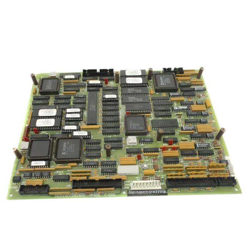
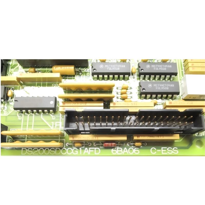
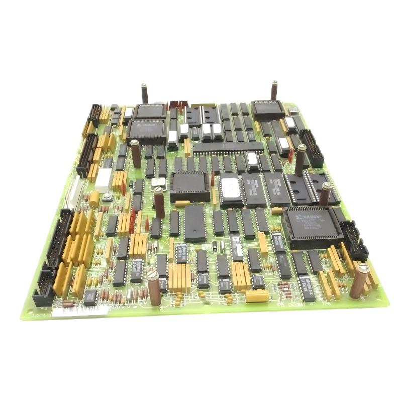
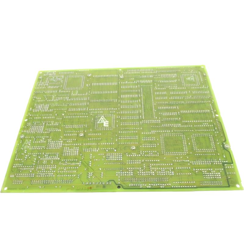
- GE
- DS215SDCCG1AZZ01A DS200SDCCG1AFD
- Drive Control Board
- USA
- 200 × 150 × 50 mm
- 0.95 kg
- Xiamen, China
- New & In Stock
- T/T, PayPal, Western Union
- 1 Year
- 1-3 Working Days
- DHL, UPS, TNT, FedEx and EMS.
- 24-Hour Service
- COO
- 50
Our advantage

Global Logistics
We have a 10-year logistics and express cooperation agreement, so our products can be shipped to any place in the world.

Brand new and original
Our products are imported in bulk from the place of origin. Because of the cooperative relationship, our products are all original and 100% new.

24-hour service
We provide 7*24 hours service to our customers. We will be there whenever you need us.

Price advantage
All our products are priced very favorably because we have our own warehouse and supply.
| Company Information | |||
| [email protected] | |||
| Mobile | +8615980777398 | ||
| +8615980777398 | |||
| 15980777398 |
Product Overview
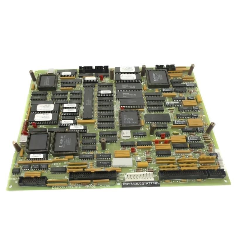
The GE DS215SDCCG1AZZ01A with the associated DS200SDCCG1AFD Drive Control Board is a specialized control assembly used in GE Mark V industrial drive and excitation systems. The DS200SDCCG1AFD is the functional Drive Control Card, while the DS215 designation identifies the related hardware configuration used in the larger GE Speedtronic architecture.
The SDCC family is designed to provide the main processing and interface functions required by compatible drives. It handles drive-control logic, motor-related signal processing, customer I/O, and communication with other control boards. This makes the SDCC one of the important processing elements within a compatible GE industrial drive system.
The DS215SDCCG1AZZ01A is particularly relevant to maintenance of legacy GE equipment because the DS215 version can incorporate the hardware and memory configuration required by the installed application. When replacing an existing board, technicians should therefore identify the complete DS215 part number rather than selecting a DS200 board solely because the functional description appears similar.
The specified assembly has dimensions of 200 × 150 × 50 mm and a weight of 0.95 kg. Its exact installation position and connected components depend on the GE drive or control system in which it is installed.
Technical Specifications
| Parameter | Details |
|---|---|
| Manufacturer | GE General Electric |
| Model | DS215SDCCG1AZZ01A |
| Associated Board | DS200SDCCG1AFD |
| Product Type | Drive Control Board / Drive Control Card |
| Functional Acronym | SDCC |
| Product Family | GE Mark V / DS200 / DS215 |
| Primary Function | Drive control, processing and signal interface |
| Control Processing | Multi-processor drive-control architecture |
| Signal Processing | Motor, drive and customer I/O signal processing |
| Communication | Interfaces with associated control and communication boards |
| Application | Industrial drive and excitation systems |
| Installation | Industrial control cabinet / drive system |
| Dimensions | 200 × 150 × 50 mm |
| Weight | 0.95 kg |
| Construction | Industrial printed circuit board assembly |
| Service Application | Maintenance, replacement and system restoration |
Function and Working Principle
The primary function of the DS200SDCCG1AFD is to act as a central control board for a compatible GE drive or exciter. It contains the processing and interface circuitry required to coordinate drive operation and communicate with other parts of the system.
The board uses multiple processing resources to handle different control tasks. This architecture allows drive-control calculations, motor-related processing, system management, and interface functions to be handled within the same control platform.
The SDCC control architecture can process information associated with:
- Motor operating conditions
- Drive control commands
- Speed and position information
- Current and voltage-related signals
- Customer input and output signals
- Drive status information
- Diagnostic information
- Communication data
The processed information is used to determine appropriate control actions. Commands can then be transferred through the associated drive interface circuitry to the relevant power and control hardware.
The board is therefore not simply an interface PCB. It provides substantial control-processing functionality and forms part of the real-time control path between the system processor, drive electronics, feedback circuits, and external equipment.
Role in Industrial Control Systems
The DS215SDCCG1AZZ01A plays an important role within compatible GE industrial drive architectures because it connects processing functions with the physical drive-control system.
A typical system can contain several functional layers. Field devices and sensors provide feedback information, I/O circuits transfer that information to the control system, the SDCC processes the information, and the drive power electronics execute the resulting control commands.
The board can therefore interact with:
- GE Mark V control processors
- Drive power electronics
- Motor feedback devices
- Current and voltage sensing circuits
- Customer I/O circuits
- LAN communication hardware
- Signal processing boards
- Terminal and interface boards
- Operator interface equipment
This arrangement allows the drive system to continuously monitor operating conditions and adjust its control response according to configured requirements.
Because the SDCC is positioned close to the center of the control architecture, a fault on the board can affect several functions simultaneously. Symptoms may include drive startup problems, loss of feedback, communication errors, incorrect control response, or system diagnostic alarms.
Industrial Applications
The GE DS215SDCCG1AZZ01A and DS200SDCCG1AFD are associated with GE industrial drive and control equipment. The SDCCG1 configuration is particularly associated with compatible drive applications within the GE Mark V family.
Potential application areas include:
- Industrial motor drives
- AC drive systems
- DC drive systems
- Excitation systems
- Power-generation equipment
- Turbine auxiliary systems
- Industrial rotating machinery
- Legacy GE Speedtronic installations
In these applications, accurate control of current, speed, position, and other operating parameters is important for maintaining stable equipment performance.
The board can also participate in system diagnostics and communication, allowing operators and maintenance personnel to identify abnormal conditions and evaluate the status of the drive system.
DS200SDCCG1AFD Drive Control Board
The DS200SDCCG1AFD is the associated functional Drive Control Board specified for this assembly. It provides the primary control circuitry and processing functions required by the compatible drive system.
The board contains multiple microprocessors and shared memory resources designed to support different control tasks. This processing structure enables the drive-control system to handle several operations at the same time.
| Processing Area | Typical Function |
|---|---|
| Drive Control Processing | Manages overall drive-control operations |
| Motor Control Processing | Handles motor-specific control functions |
| Signal Processing | Processes drive and feedback signals |
| I/O Processing | Handles customer and system I/O information |
| Communication | Exchanges information with compatible system boards |
| Diagnostics | Supports fault and operating-status monitoring |
The board can also accommodate additional interface hardware depending on the specific drive configuration. This modular architecture allows the SDCC platform to support different drive applications.
DS215SDCCG1AZZ01A and DS200SDCCG1AFD Relationship
The relationship between the two identifiers is important when selecting replacement hardware.
| Identification | Role |
|---|---|
| DS215SDCCG1AZZ01A | DS215-series Drive Control Card assembly identification |
| DS200SDCCG1AFD | Associated SDCC Drive Control Board / functional board number |
The DS200SDCCG1AFD identifies the functional SDCC board, while the DS215SDCCG1AZZ01A represents the corresponding DS215 configuration used in the system.
This distinction matters because DS215 boards can include memory or configuration hardware associated with the installed application. A DS200 board with a similar functional description should therefore not automatically be considered a complete equivalent.
When replacing an existing DS215SDCCG1AZZ01A, the original board configuration, memory devices, jumpers, firmware, connectors, and associated option cards should be checked carefully.
Installation and System Integration
Installation of a GE SDCC Drive Control Board requires careful attention to board configuration and cable connections. The SDCC is connected to multiple parts of the drive system, so an incorrectly installed connector can affect more than one function.
A recommended installation procedure includes:
- Place the drive system into the approved maintenance state.
- Disconnect and isolate all relevant power sources.
- Verify that the equipment is electrically safe before handling the board.
- Record the complete DS215SDCCG1AZZ01A identification.
- Record the DS200SDCCG1AFD board identification and revision.
- Document all connector and cable positions.
- Record jumper and configuration positions before removing the original board.
- Inspect the replacement PCB for physical damage.
- Check connectors for contamination, corrosion, or bent contacts.
- Transfer applicable configuration hardware according to the approved maintenance procedure.
- Install the board in the correct rack or mounting position.
- Reconnect all cables carefully.
- Verify connector seating and board mounting.
- Restore power according to the commissioning procedure.
- Check diagnostics and communication status.
- Test drive operation under controlled conditions.
Configuration matching is particularly important. Hardware jumpers and stored configuration information can influence how the board operates within the drive system. The replacement board should therefore be configured to match the original application before full commissioning.
Compatible System Components
The SDCC board normally operates as part of a larger GE drive-control system. Several types of boards and devices can be associated with it.
| Component | Type | Function |
|---|---|---|
| DS200SDCCG1AFD | Drive Control Board | Primary drive-control processing |
| DS215SDCCG1AZZ01A | Drive Control Assembly | DS215-series SDCC configuration |
| LAN Communication Board | Communication Hardware | Provides network communication functions |
| Signal Processing Board | Signal Interface | Expands drive signal-processing functions |
| Power Supply / Interface Board | Power Interface | Provides required control power and system interfaces |
| Terminal Board | Interface Hardware | Connects external signals and wiring |
| Feedback Devices | Sensor Hardware | Provides speed, position and operating feedback |
| Drive Power Electronics | Power Hardware | Executes motor-control commands |
Drive Control and Signal Processing
The SDCC board is responsible for processing information required for drive operation. A typical control sequence begins with feedback from the motor or associated equipment.
Feedback information can include speed, current, position, or other parameters depending on the application. The control board evaluates this information together with operator commands and configured control parameters.
The resulting control decisions are then transferred to the relevant drive-control and power circuitry.
The overall control sequence can be represented as:
Feedback Devices → Interface / I/O → SDCC Processing → Drive Control → Power Electronics → Motor
The SDCC therefore forms a central processing point in the control loop.
In addition to control calculations, the board can manage system-level functions and exchange information with other boards. This integrated architecture allows the drive to respond to changing operating conditions while maintaining communication with the wider control system.
Configuration and Memory Considerations
One important consideration when replacing an SDCC board is configuration data. The DS215 version of the SDCC family can contain memory devices associated with the installed application.
These memory devices may contain factory-programmed configuration information and field-adjustable parameters. For this reason, technicians should compare the memory configuration of the original board with the replacement board before installation.
Hardware jumpers can also affect board operation. The original jumper configuration should be documented before removal, and the replacement board should be configured appropriately for the target application.
Incorrect configuration can result in symptoms that resemble hardware failure, including communication problems, incorrect drive operation, or failure to initialize.
Maintenance and Troubleshooting Considerations
When troubleshooting the DS215SDCCG1AZZ01A, it is important to separate board-level problems from faults originating elsewhere in the drive system.
| Observed Condition | Possible Area to Check |
|---|---|
| Drive does not start | Control power, SDCC board, configuration and enable signals |
| Drive loses feedback | Feedback devices, wiring, interface boards and SDCC inputs |
| Incorrect motor response | Control configuration, feedback circuits and drive-control processing |
| Communication failure | Communication board, cables, connectors and SDCC interface |
| Intermittent operation | Power stability, connectors, wiring and PCB condition |
| Diagnostic fault codes | Board diagnostics, connected hardware and system configuration |
| Repeated board failure | External power conditions, wiring and associated drive electronics |
A visual inspection should be performed before removing the board. Technicians should look for discoloration, damaged components, contamination, corrosion, loose connectors, or signs of overheating.
If a replacement board produces the same fault as the original, the external system should be investigated. Power supplies, feedback circuits, communication hardware, terminal boards, and drive power electronics can all cause symptoms that appear to originate from the SDCC.
Systematic troubleshooting is therefore more effective than replacing the control board without testing the surrounding equipment.
Recommended Alternative Models
The following models are related to the GE Mark V drive-control family and can be useful for comparison or spare-parts planning. They should not automatically be treated as direct substitutes because application, revision, firmware, and hardware configuration can differ.
| Model | Type | Key Feature | Application |
|---|---|---|---|
| DS215SDCCG1AZZ01A | Drive Control Board | DS215 SDCC drive-control configuration | GE Mark V drive systems |
| DS200SDCCG1AFD | Drive Control Board | Primary SDCC drive controller | GE Mark V drive and exciter applications |
| DS200SDCCG1AGD | Drive Control Board | Related SDCCG1 hardware revision | Compatible GE drive systems |
| DS200SDCCG1AHD | Drive Control Board | Related SDCCG1 hardware revision | GE Mark V applications |
| DS200SDCCG4AFD | Drive Control Board | Different SDCC group configuration | GE Mark V drive systems |
| DS215SLCCG1AZZ01A | LAN Communication Card | Communication interface for compatible systems | GE Mark V control networks |
| DS215GASQG4AZZ01A | Drive Control Assembly | Drive control and communication configuration | GE Mark V industrial systems |
Replacement recommendation: If the installed system uses DS215SDCCG1AZZ01A, the same complete DS215 configuration should be preferred. The DS200SDCCG1AFD can identify the functional board, but technicians should verify memory, firmware, jumpers, connectors, and application requirements before substituting one configuration for another.
Key Advantages
- Designed for GE Mark V industrial drive-control architecture
- Provides central drive-control processing
- Supports motor and drive signal processing
- Handles customer and system I/O functions
- Supports communication with associated control boards
- Uses a multi-processor control architecture
- Suitable for compatible AC and DC drive applications
- Useful for legacy GE industrial maintenance projects
- Supports continuous monitoring and control of drive operation
Technical FAQs
What is the GE DS215SDCCG1AZZ01A?
The GE DS215SDCCG1AZZ01A is a Drive Control Board assembly associated with the GE Mark V industrial control platform. The functional board identified with this configuration is the DS200SDCCG1AFD.
What is the main function of the DS200SDCCG1AFD?
The DS200SDCCG1AFD provides primary drive-control processing. It handles drive and motor control functions, signal processing, customer I/O, and interfaces with other system boards.
What is SDCC?
SDCC is the functional acronym used for the Drive Control Card. It identifies a family of GE control boards designed to provide processing and interface functions for compatible drive systems.
What are the dimensions of the DS215SDCCG1AZZ01A?
The specified dimensions are 200 × 150 × 50 mm.
How much does the DS215SDCCG1AZZ01A weigh?
The specified weight is 0.95 kg.
Where is the DS215SDCCG1AZZ01A used?
It is associated with compatible GE Mark V industrial drive and excitation systems, including applications involving motors, rotating machinery, and power-generation equipment.
What processors are associated with the DS200SDCCG1AFD?
The DS200SDCCG1AFD uses multiple processing resources for drive control, motor control, and signal-processing functions. The architecture is designed to divide different control tasks among dedicated processing sections.
Can DS200SDCCG1AFD replace DS215SDCCG1AZZ01A directly?
Not automatically. Although DS200SDCCG1AFD identifies the associated functional board, the DS215 configuration can include application-specific memory and configuration hardware. The complete installed configuration should be verified before replacement.
What components work with the SDCC board?
Depending on the system, associated components can include LAN communication boards, signal-processing boards, terminal boards, power/interface boards, feedback devices, drive power electronics, and other GE Mark V control hardware.
What should be checked before installing a replacement SDCC board?
The complete part number, hardware revision, memory configuration, jumper settings, firmware, connectors, and associated option boards should be checked. The original wiring should also be documented before removal.
Conclusion
The GE DS215SDCCG1AZZ01A DS200SDCCG1AFD Drive Control Board is an important control component for compatible GE Mark V industrial drive and excitation systems. The DS200SDCCG1AFD provides the primary drive-control processing, signal handling, customer I/O, and system interface functions required by the associated drive architecture.
The SDCC platform uses a multi-processor design to handle drive-control and motor-related processing tasks. It can work with feedback devices, communication boards, signal-processing hardware, terminal boards, and drive power electronics to create a complete industrial control system.
With specified dimensions of 200 × 150 × 50 mm and a weight of 0.95 kg, the DS215SDCCG1AZZ01A is suitable for integration into compatible GE industrial equipment. For maintenance and replacement work, accurate identification is particularly important because DS200 and DS215 versions can differ in configuration and stored application information.
For system integrators and maintenance engineers, matching the complete DS215SDCCG1AZZ01A configuration, including the associated DS200SDCCG1AFD board, memory, firmware, jumpers, and connected hardware, can help reduce installation errors and improve the reliability of replacement work. Proper configuration and systematic commissioning are essential for restoring stable operation in legacy GE Mark V drive-control systems.