

ProductPRODUCT
Featured products
Contact Us
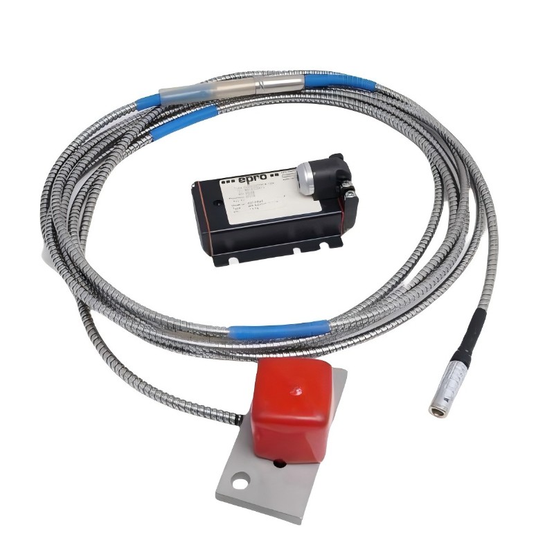
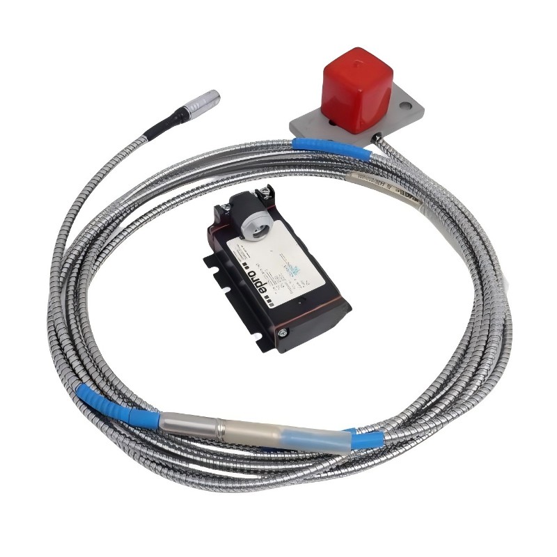
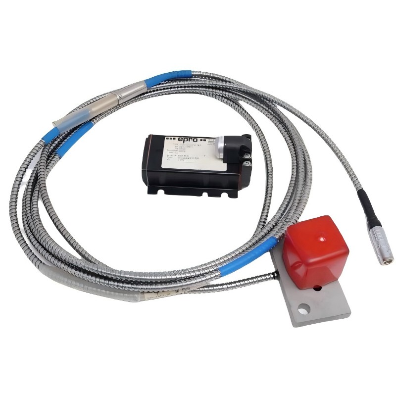
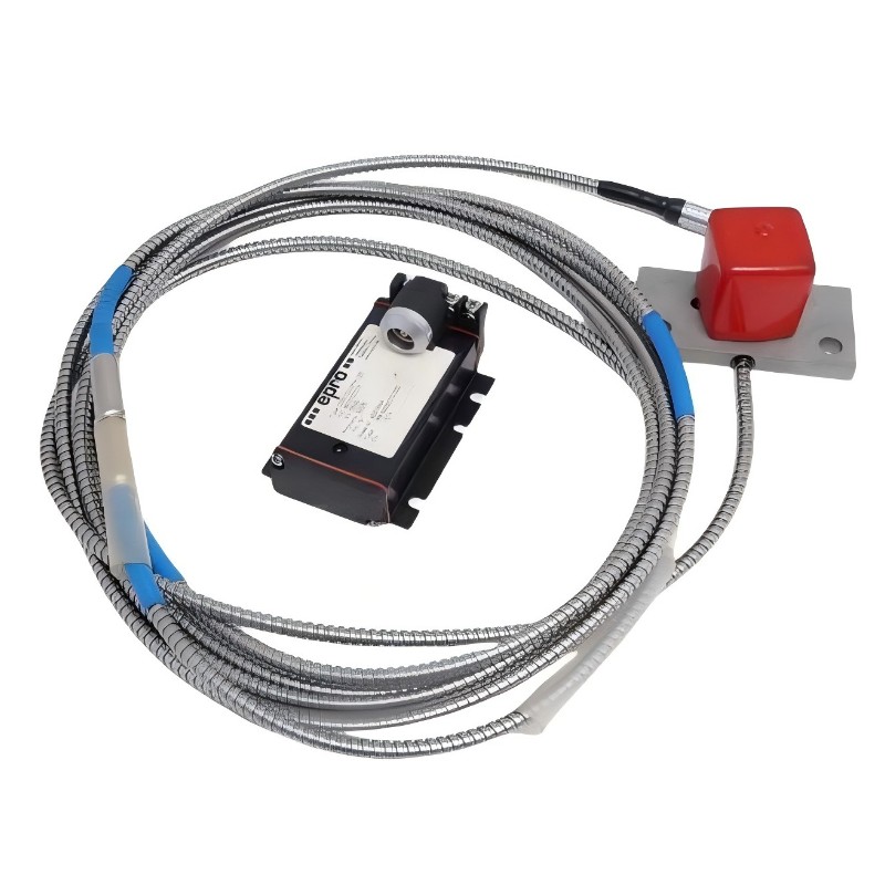
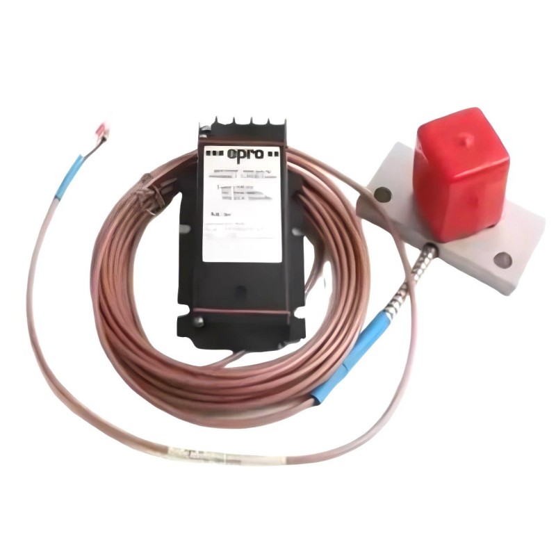
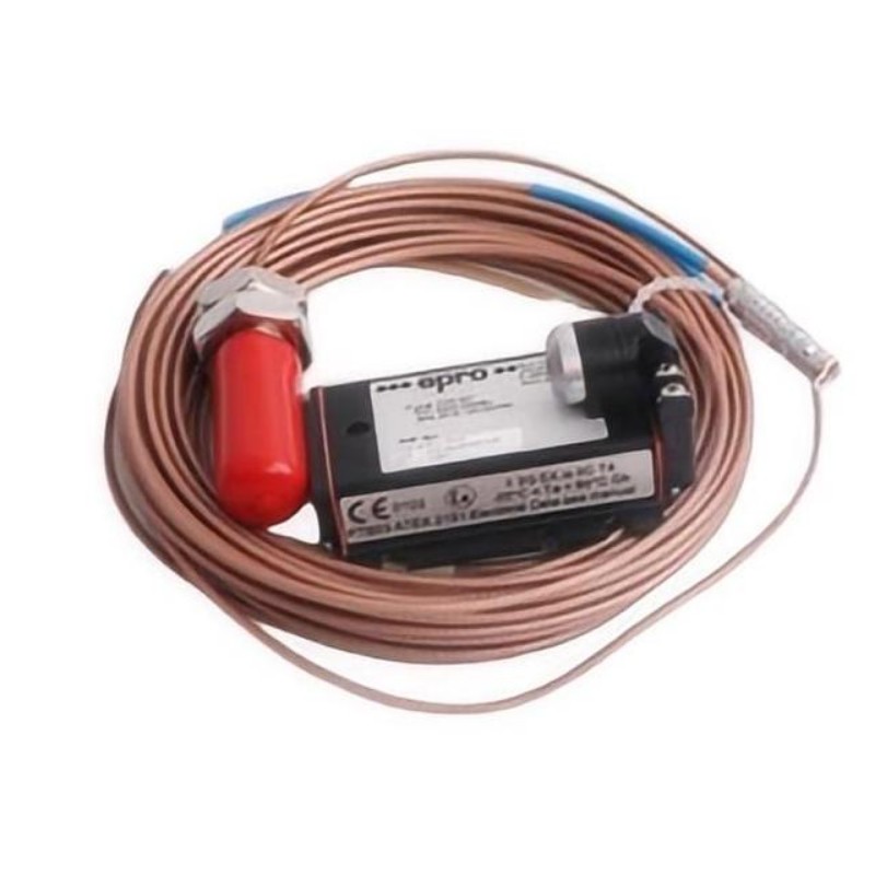
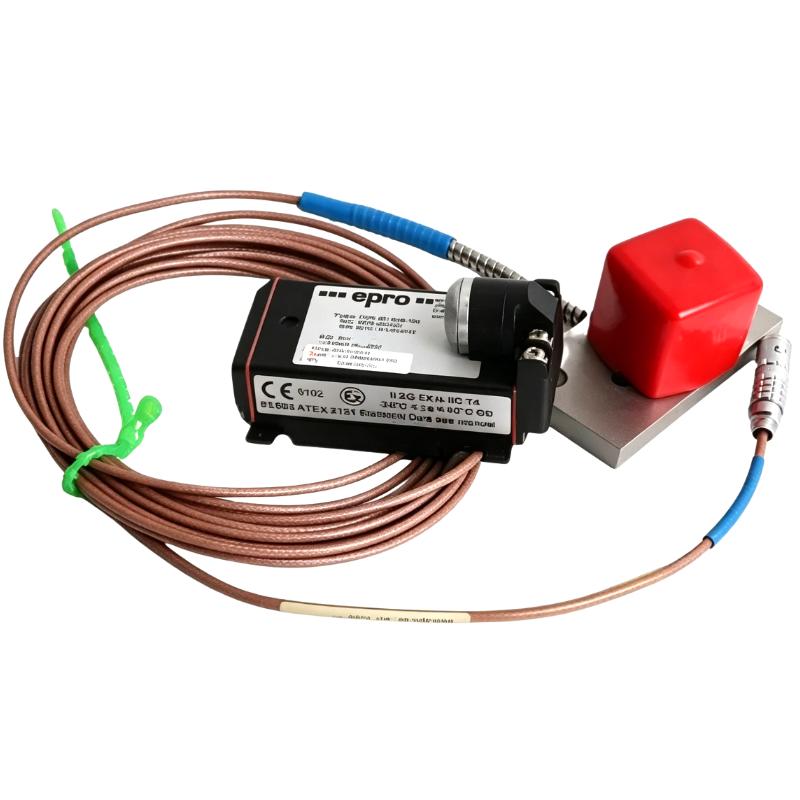
- Epro
- PR6426/000-110
- 32 mm Eddy Current Sensor
- Germany
- 32 mm
- 0.8 kg
- Xiamen, China
- New & In Stock
- T/T, PayPal, Western Union
- 1 Year
- 1-3 Working Days
- DHL, UPS, TNT, FedEx and EMS.
- 24-Hour Service
- COO
- 3
Our advantage

Global Logistics
We have a 10-year logistics and express cooperation agreement, so our products can be shipped to any place in the world.

Brand new and original
Our products are imported in bulk from the place of origin. Because of the cooperative relationship, our products are all original and 100% new.

24-hour service
We provide 7*24 hours service to our customers. We will be there whenever you need us.

Price advantage
All our products are priced very favorably because we have our own warehouse and supply.
| Company Information | |||
| [email protected] | |||
| Mobile | +8615980777398 | ||
| +8615980777398 | |||
| 15980777398 |
Product Overview
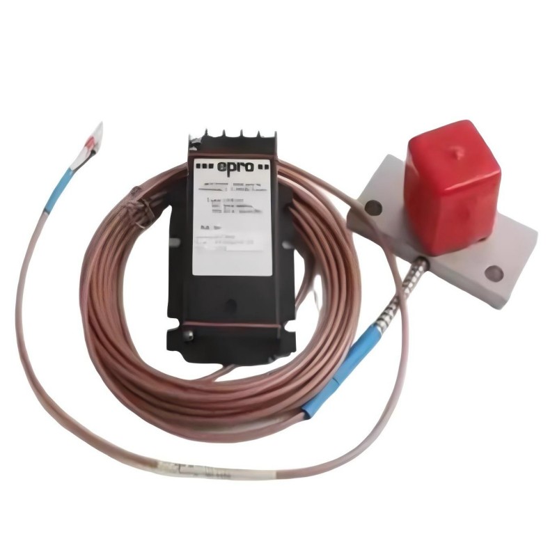
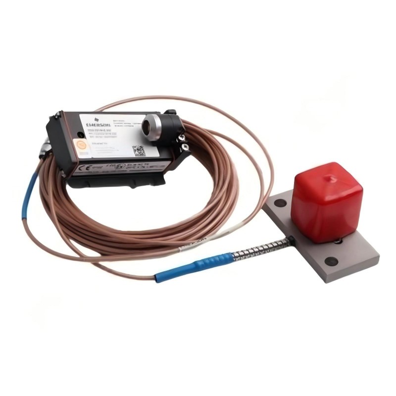
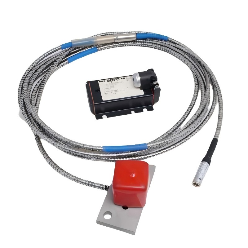
The Epro PR6426/000-110 is a 32 mm eddy current sensor used to measure shaft displacement without physical contact. It belongs to the PR6426 family of sensors for critical rotating machinery, including steam turbines, gas turbines, hydro turbines, compressors, pumps, and industrial fans. Its primary task is to detect changes in the distance between the probe and a conductive shaft surface, allowing a monitoring system to track rotor position and movement during operation.
In a turbine or large compressor, shaft position can change as the machine warms up, load conditions shift, or thrust-bearing behavior changes. The PR6426/000-110 can be installed near the shaft to measure these movements continuously. The resulting signal helps engineers monitor axial or radial displacement, assess shaft eccentricity, and identify changes that warrant further investigation.
The PR6426 family is intended for larger shafts and offers a standard static measuring range of ±4.0 mm. Its 32 mm sensing head is suited to installations where the available target area and shaft geometry meet the probe’s requirements. Measurement accuracy depends on the initial air gap, target material, mounting alignment, and the compatibility of the sensor with its associated converter.
The PR6426/000-110 is commonly listed in configurations paired with a CON021 signal converter. The converter processes the probe response into an electrical output that can be interpreted by the monitoring system. Before installing a replacement, check the complete model code, connector arrangement, cable configuration, and converter compatibility rather than assuming that all PR6426 variants are interchangeable.
For maintenance personnel, the value of this sensor lies in the trend information it supplies. A gradual shift in shaft position may require a different investigation from a sudden signal change. Reviewing displacement data alongside vibration, bearing temperature, and operating load helps put the measurement into its mechanical context.
Technical Specifications
| Parameter | Specification |
|---|---|
| Manufacturer | Epro |
| Model | PR6426/000-110 |
| Product Family | PR6426 |
| Product Type | 32 mm Eddy Current Sensor |
| Measuring Principle | Non-contact eddy current |
| Sensor Head Diameter | 32 mm |
| Static Measuring Range | ±4.0 mm |
| Sensitivity | 2 V/mm (50.8 mV/mil), maximum deviation ±1.5% |
| Nominal Center Air Gap | Approximately 5.5 mm |
| Long-Term Drift | Less than 0.3% |
| Standard Reference Target Material | Ferromagnetic steel, 42CrMo4 |
| Operating Temperature | -35 to +175°C |
| Short-Term Temperature Excursion | Up to +200°C for less than 4 hours |
| Maximum Cable Temperature | +200°C |
| Sensor Sleeve Material | Stainless steel |
| Cable Material | PTFE |
| Dynamic Frequency Range | Up to 20 kHz (-3 dB), depending on the measuring chain |
| Typical Cable Length Options | 4 m, 5 m, 8 m, and 10 m |
| Compatible Conversion Equipment | CON021 configuration; verify alternatives against the sensor connection and monitoring system |
| Typical Applications | Turbines, compressors, pumps, and fans |
| Weight | 0.8 kg |
Product Features
- Non-contact shaft measurement: Detects changes in the gap between the probe and a rotating metal surface.
- 32 mm sensing head: Suited to large-shaft displacement applications within the PR6426 family.
- Wide static measurement range: Supports a nominal range of ±4.0 mm under the standard configuration.
- Continuous displacement tracking: Supplies data for observing changes in rotor position during machine operation.
- Converter-based output: Works with compatible signal-conversion equipment to make probe measurements available to monitoring systems.
- Industrial materials: Uses a stainless-steel sleeve and PTFE cable in the specified sensor assembly.
- Dynamic response: Supports shaft-motion monitoring within the bandwidth of the complete measuring chain.
- Condition monitoring integration: Can be incorporated into compatible machinery monitoring and protection arrangements.
Working Principle
The PR6426/000-110 uses an electromagnetic field to measure the distance between its sensing face and a conductive metal target. When the field interacts with the shaft, eddy currents form in the target. Changes in the gap alter the electrical response of the sensor circuit, allowing displacement to be measured without contact.
The measurement chain typically follows this path:
Rotating Shaft → PR6426/000-110 Sensor → CON021 Signal Converter → Monitoring System
As the shaft moves closer to the probe, the gap decreases. As it moves away, the gap increases. Within the configured linear region, the sensor response changes in proportion to the displacement. The converter processes this response into an output that the monitoring equipment can display, trend, and evaluate against configured limits.
The standard PR6426 configuration supports a static range of ±4.0 mm, with nominal sensitivity of 2 V/mm for the specified reference target. The actual signal range depends on the converter configuration. Where the system supports different output modes or extended measuring ranges, the probe and converter settings must be matched before commissioning.
Target material is a key part of the measurement relationship. The standard reference is 42CrMo4 ferromagnetic steel. If the actual shaft material differs, its electrical and magnetic characteristics may affect the output for a given gap. Target compatibility and calibration should therefore be checked when installing the sensor.
The initial air gap determines the probe’s operating point within its measuring range. An incorrect setting can reduce the available measurement travel or cause part of the expected shaft movement to fall outside the linear region. Correct positioning is particularly important when the sensor is used to monitor movement in both directions.
The probe measures displacement; it does not independently generate a machine shutdown command. Alarm and trip decisions are handled by the connected monitoring or protection system according to its configured logic.
Role in a Machinery Condition Monitoring System
The PR6426/000-110 acts as the sensing element in a shaft-displacement channel. Its output represents changes in the distance between the sensor and the shaft, while the converter and monitoring equipment turn that response into usable operating data.
Rotating Shaft → PR6426/000-110 → CON021 Converter → Monitoring Channel → Alarm or Protection Logic
| System Element | Function |
|---|---|
| PR6426/000-110 Sensor | Detects changes in the gap between the probe and the conductive shaft |
| CON021 Signal Converter | Processes the probe signal into a configured electrical output |
| Machinery Monitoring System | Displays and records displacement measurements |
| Protection System | Applies alarm or trip logic where supported |
| Shaft or Rotor | Provides the conductive target surface |
| Sensor Mounting Assembly | Holds the probe at the required measurement position |
| Sensor Cable and Connector | Carries the probe signal to the converter |
| Plant Control System | Uses available monitoring data for operational supervision |
Industrial Applications
| Application | Typical Use |
|---|---|
| Steam Turbines | Tracking axial or radial shaft movement during startup and load changes |
| Gas Turbines | Monitoring rotor position as part of machinery condition assessment |
| Hydro Turbines | Measuring shaft displacement in turbine-generator assemblies |
| Industrial Compressors | Observing changes in rotor position during continuous operation |
| Large Pumps | Monitoring shaft movement in critical pumping equipment |
| Industrial Fans | Tracking shaft position in rotating equipment requiring ongoing supervision |
| Power Generation Plants | Feeding displacement measurements into turbine monitoring systems |
| Petrochemical Facilities | Monitoring critical rotating machinery in demanding process environments |
| Machinery Protection Systems | Supplying shaft-displacement signals to compatible monitoring channels |
| Predictive Maintenance Programs | Comparing displacement trends with vibration and operating data |
Installation and Maintenance
- Confirm the complete model code: Verify that the sensor is PR6426/000-110 and that the connection and cable arrangement match the installed system.
- Inspect the mounting location: Ensure that the probe can be secured and aligned with the intended shaft measurement point.
- Set the initial air gap: Follow the applicable installation instructions and the selected converter configuration to establish the correct operating position.
- Check the target material: Confirm compatibility with the measuring-chain calibration, especially if the shaft differs from the standard 42CrMo4 reference material.
- Maintain the required clearance: Keep nearby ferrous structures outside the specified clearance zone to minimize measurement interference.
- Verify converter compatibility: Confirm that the CON021 or another proposed converter supports the specific sensor connection and required output configuration.
- Inspect the cable and connector: Look for damaged insulation, abrasion, loose connections, or signs of heat exposure.
- Protect cable routing: Avoid sharp edges, excessive bending, moving components, and sources of electrical interference.
- Validate the signal: Check that the output corresponds to the expected initial gap and selected measurement mode before placing the channel into service.
- Investigate unusual readings: Review probe alignment, target condition, cable connections, converter settings, and machine operating conditions if the signal changes unexpectedly.
- Follow machinery safety procedures: Apply the required isolation and site safety measures before accessing the probe near rotating equipment.
- Document baseline conditions: Record the model, target material, initial gap, converter configuration, and initial readings for future comparisons.
Compatible System Components
| Component | Function |
|---|---|
| Epro PR6426/000-110 Sensor | Detects shaft displacement through non-contact eddy current measurement |
| CON021 Signal Converter | Converts the sensor response into a configured electrical output |
| Compatible PR6426 Signal Converter | Provides an alternative only where the exact sensor connection and specifications are supported |
| MMS 3000 Series Monitoring Equipment | Processes compatible measurement signals for machinery monitoring |
| Sensor Mounting Assembly | Maintains the required probe position and alignment |
| Compatible Sensor Cable | Carries the probe signal to the converter |
| LEMO Connector Arrangement | Provides the sensor-side connection in applicable configurations |
| Conductive Shaft Target | Provides the metal surface used for displacement measurement |
| Machinery Monitoring Channel | Displays, records, and evaluates processed displacement data |
Recommended Related Models
| Model | Product Type | Selection Consideration |
|---|---|---|
| Epro PR6426/000-100 | 32 mm Eddy Current Sensor | Compare the complete order code, connector arrangement, and converter compatibility |
| Epro PR6426/000-101 | 32 mm Eddy Current Sensor | Verify the specific version and cable configuration before considering substitution |
| Epro PR6426/000-040 | 32 mm Eddy Current Sensor | Check the required measurement-chain configuration against the installed system |
| Epro PR6425 Series | Eddy Current Sensor | Consider when a different probe geometry or measuring range is required |
| Epro PR6424 Series | Eddy Current Sensor | Evaluate for applications where a different sensor diameter and measurement range are suitable |
Key Advantages
- Measures shaft displacement without contacting the rotating surface.
- Supports a nominal static measuring range of ±4.0 mm.
- Supplies measurement data through compatible conversion equipment.
- Supports continuous monitoring of shaft position in critical machinery.
- Helps engineers evaluate displacement trends alongside other operating measurements.
Technical FAQs
What is the main function of the PR6426/000-110?
It measures the gap between the sensor and a conductive shaft surface. Depending on its mounting position, the measurement can be used to monitor axial or radial displacement, shaft position, and eccentricity in rotating machinery.
Is the CON021 converter required for this sensor?
The PR6426/000-110 is commonly offered in a CON021 configuration. Before using a different converter, verify the connector arrangement, electrical interface, measurement range, and output requirements of the existing system.
What shaft conditions should be considered when installing the sensor?
The target material, shaft diameter, available target area, initial air gap, and probe alignment all affect measurement performance. The standard PR6426 reference target is 42CrMo4 steel, and the installation should meet the specified clearance requirements.
How can technicians distinguish a sensor problem from actual shaft movement?
Review the signal trend alongside machine load, vibration, and bearing temperature. If the reading changes unexpectedly, inspect the initial gap, mounting, cable and connector, and converter configuration before attributing the change to a mechanical fault.