

ProductPRODUCT
Featured products
Contact Us
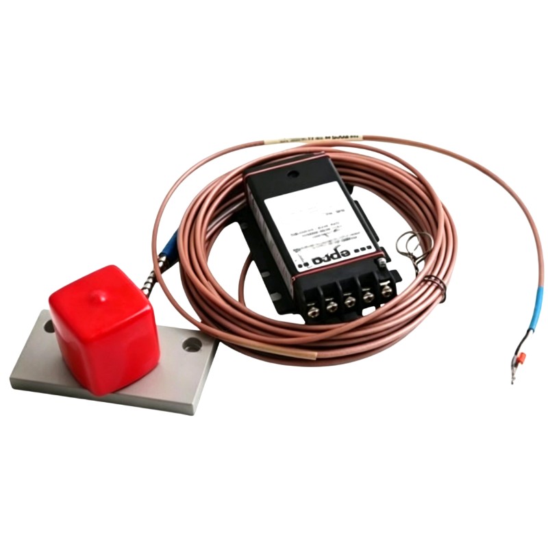
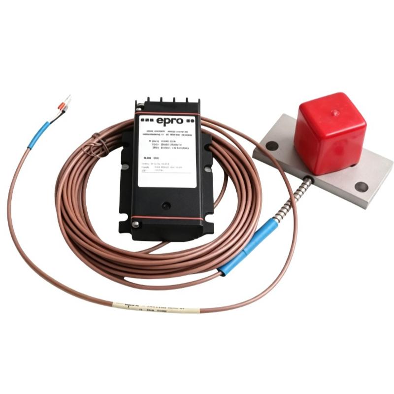
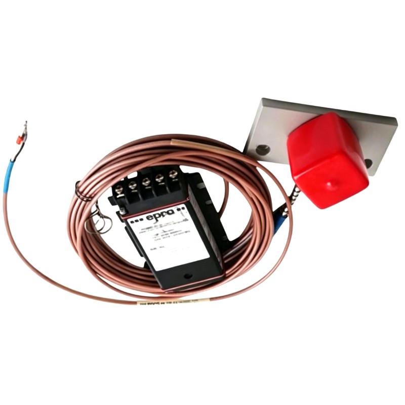
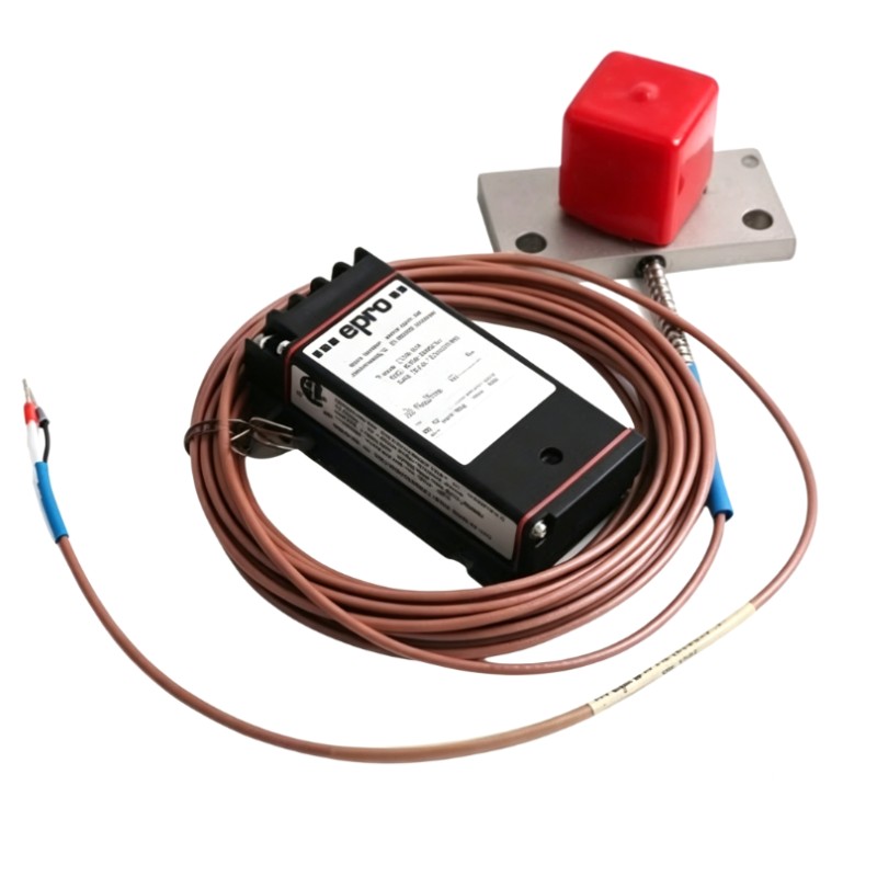
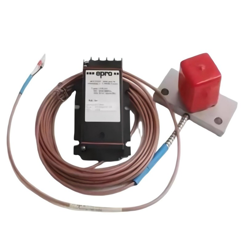
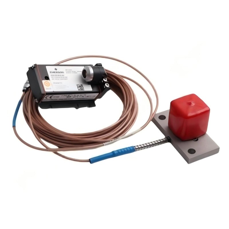
- Epro
- PR6426/000-100
- 32 mm Eddy Current Sensor
- Germany
- 32 mm
- 0.8 kg
- Xiamen, China
- New & In Stock
- T/T, PayPal, Western Union
- 1 Year
- 1-3 Working Days
- DHL, UPS, TNT, FedEx and EMS.
- 24-Hour Service
- COO
- 3
Our advantage

Global Logistics
We have a 10-year logistics and express cooperation agreement, so our products can be shipped to any place in the world.

Brand new and original
Our products are imported in bulk from the place of origin. Because of the cooperative relationship, our products are all original and 100% new.

24-hour service
We provide 7*24 hours service to our customers. We will be there whenever you need us.

Price advantage
All our products are priced very favorably because we have our own warehouse and supply.
| Company Information | |||
| [email protected] | |||
| Mobile | +8615980777398 | ||
| +8615980777398 | |||
| 15980777398 |
Product Overview
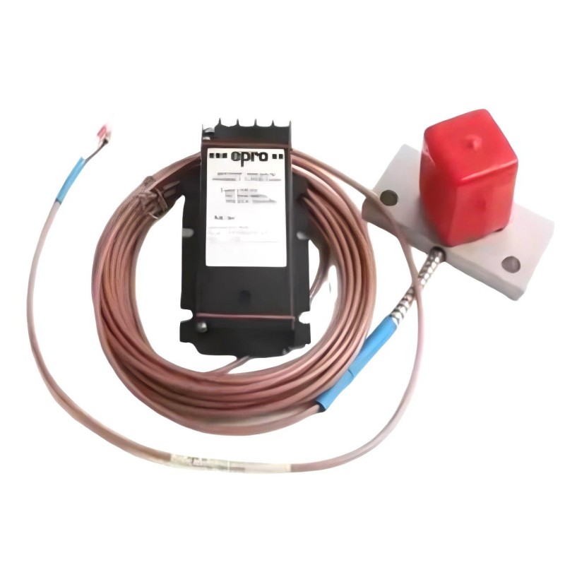
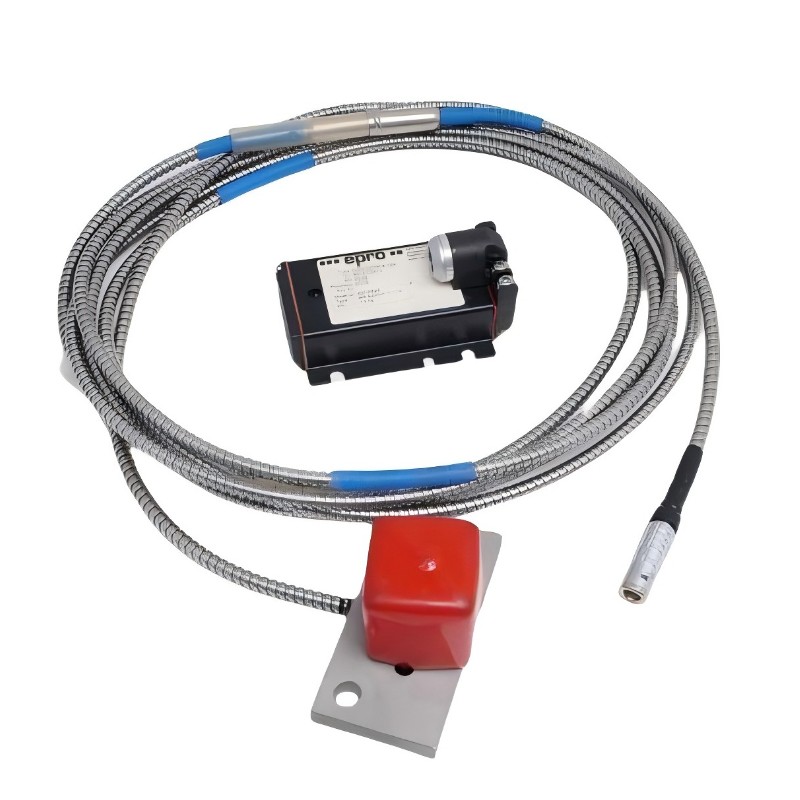
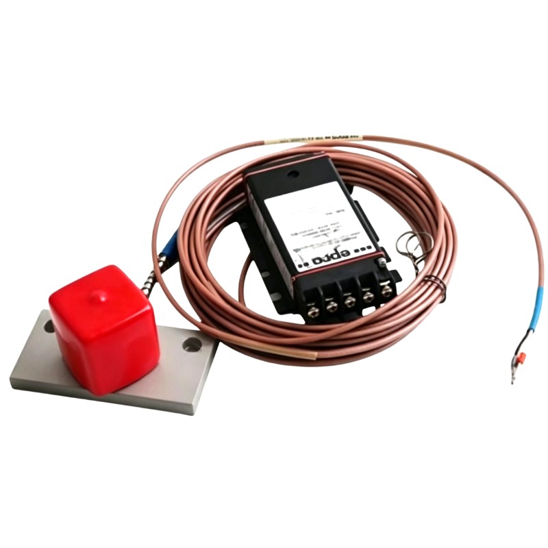
The Epro PR6426/000-100 is a 32 mm eddy current sensor used for non-contact measurement of shaft displacement in large rotating machinery. It belongs to the PR6426 family, which is intended for monitoring axial and radial shaft movement, eccentricity, and other changes in rotor position. Typical applications include steam turbines, gas turbines, hydro turbines, industrial compressors, pumps, and fans.
In a turbine bearing assembly, changes in rotor position can occur as the machine heats up, operating loads vary, or bearing conditions deteriorate. The PR6426/000-100 measures the changing distance between its sensing face and the conductive shaft surface. Its output can be processed by compatible signal-conversion equipment and used by a machinery monitoring system to track shaft position during operation.
The 32 mm sensing head is intended for applications involving large shafts and a relatively wide displacement range. The PR6426 family supports static measurement up to ±4.0 mm under its standard configuration. This is useful where the monitoring system needs to detect significant changes in shaft position rather than only small-amplitude vibration. The sensor’s actual measurement performance depends on the target material, initial air gap, converter configuration, and installation geometry.
The PR6426/000-100 is a sensing component, not a standalone protection instrument. It forms part of a measuring chain that includes compatible signal-conversion equipment or an integrated monitoring interface. The complete configuration determines how the sensor signal is converted, displayed, and evaluated by the machinery monitoring system.
For maintenance engineers, shaft-displacement data can help distinguish gradual changes in rotor position from sudden mechanical events. When a measurement deviates from its established trend, the sensor mounting, target surface, cable connections, converter, and other machine readings should be checked before attributing the change to a particular mechanical fault.
Technical Specifications
| Parameter | Specification |
|---|---|
| Manufacturer | Epro |
| Model | PR6426/000-100 |
| Product Family | PR6426 |
| Product Type | 32 mm Eddy Current Sensor |
| Measuring Principle | Non-contact eddy current |
| Sensor Head Diameter | 32 mm |
| Static Measuring Range | ±4.0 mm |
| Sensitivity | 2 V/mm (50.8 mV/mil), maximum deviation ±1.5% |
| Nominal Center Air Gap | Approximately 5.5 mm |
| Long-Term Drift | Less than 0.3% |
| Standard Reference Target Material | Ferromagnetic steel, 42CrMo4 |
| Operating Temperature | -35 to +180°C |
| Short-Term Temperature Excursion | Up to +200°C for less than 4 hours |
| Maximum Cable Temperature | +200°C |
| Sensor Sleeve Material | Stainless steel |
| Cable Material | PTFE |
| Dynamic Frequency Range | Up to 20 kHz (-3 dB), depending on the measuring chain |
| Typical Cable Length | 4 m continuous cable for the standard configuration |
| Compatible Conversion Equipment | CON 011, CON 021, CON 031, CON 041, or supported MMS 3000 series configurations |
| Typical Applications | Turbines, compressors, pumps, and fans |
| Weight | 0.8 kg |
Product Features
- Non-contact displacement measurement: Detects shaft movement without physical contact with the rotating surface.
- 32 mm sensing head: Suited to large-shaft measurement applications within the PR6426 family.
- Wide static measuring range: Supports displacement measurement up to ±4.0 mm under the standard configuration.
- Continuous shaft monitoring: Supplies measurement data for tracking changes in rotor position during operation.
- Converter-based signal processing: Works with compatible conversion equipment to make displacement data available to monitoring systems.
- Industrial construction: Uses a stainless-steel sleeve and PTFE cable for the specified sensor assembly.
- High-temperature capability: Supports demanding machinery environments within the applicable temperature limits.
- Condition monitoring integration: Can be used as part of a larger machinery monitoring and protection arrangement.
Working Principle
The PR6426/000-100 measures the gap between its sensing face and a conductive metal target using the eddy current principle. The sensor generates an electromagnetic field that interacts with the metal shaft, inducing eddy currents in the target. Changes in the gap alter the electrical response of the sensor circuit.
A compatible signal converter processes this response and produces an output corresponding to the measured displacement. The basic measurement path is:
Rotating Shaft → PR6426/000-100 Sensor → Signal Converter → Machinery Monitoring System
When the shaft moves toward the sensor, the gap decreases; when it moves away, the gap increases. Within the configured linear measuring range, these changes produce corresponding variations in the measurement signal. The monitoring system can use the output to display displacement, record operating trends, or compare the measurement against configured alarm limits.
The standard PR6426 configuration supports static measurement up to ±4.0 mm, with a nominal sensitivity of 2 V/mm for the specified reference target. If a wider measurement span is needed, a suitable extended-range converter configuration may be required. The sensitivity and output characteristics must be verified for the complete measuring chain.
Target material affects the relationship between gap and output. The standard reference material is 42CrMo4 ferromagnetic steel. If the actual shaft uses another material, its electrical and magnetic properties may influence the sensor response, so the target and measuring-chain calibration must be compatible.
Initial-gap adjustment is also important. The sensor should be positioned within the intended measurement range, with sufficient travel available for the expected shaft movement in both directions. An incorrectly set gap can reduce the usable linear range or result in misleading displacement readings.
The sensor supplies measurement information rather than making independent alarm or shutdown decisions. Those functions depend on the connected monitoring or protection equipment and its configured logic.
Role in a Machinery Condition Monitoring System
The PR6426/000-100 serves as the sensing element in a shaft-displacement measurement channel. It detects changes in the distance between the probe and the shaft, while compatible conversion and monitoring equipment process the signal for operational assessment.
Rotating Shaft → PR6426/000-100 → Signal Converter → Monitoring Channel → Alarm or Protection Logic
| System Element | Function |
|---|---|
| PR6426/000-100 Sensor | Detects changes in the gap between the sensing face and the conductive shaft |
| Compatible Signal Converter | Processes the sensor response and produces the configured measurement output |
| Machinery Monitoring System | Displays, records, and evaluates shaft-displacement data |
| Protection System | Applies configured alarm or trip logic where supported |
| Shaft or Rotor | Provides the conductive target surface |
| Sensor Mounting Assembly | Maintains the required sensor position and initial air gap |
| Sensor Cable | Carries the measurement signal to the converter |
| Plant Control System | Uses available monitoring data for operational supervision |
Industrial Applications
| Application | Typical Use |
|---|---|
| Steam Turbines | Monitoring axial and radial shaft displacement as operating loads change |
| Gas Turbines | Tracking rotor movement during continuous machinery operation |
| Hydro Turbines | Measuring shaft position in turbine-generator assemblies |
| Industrial Compressors | Monitoring rotor displacement and identifying changes in mechanical behavior |
| Large Pumps | Measuring shaft movement in critical pumping equipment |
| Industrial Fans | Tracking shaft position in rotating equipment requiring continuous supervision |
| Power Generation Plants | Supplying displacement data to turbine monitoring systems |
| Petrochemical Facilities | Monitoring critical rotating machinery under demanding process conditions |
| Machinery Protection Systems | Providing displacement measurements to compatible monitoring channels |
| Predictive Maintenance Programs | Tracking shaft-position trends to support condition assessment and maintenance planning |
Installation and Maintenance
- Verify the complete model number: Confirm that the sensor is PR6426/000-100 and that its cable and connection arrangement match the intended installation.
- Check the mounting position: Secure the sensor assembly and align its sensing face with the intended shaft measurement point.
- Set the initial air gap: Follow the applicable installation procedure to establish the correct starting position for the selected measurement range.
- Confirm target-material compatibility: Check that the shaft material matches the reference calibration or that the required adjustment has been accounted for.
- Maintain installation clearance: Follow the specified clearance requirements around the probe to limit interference from nearby ferrous structures.
- Verify converter compatibility: Confirm that the selected converter supports the sensor and the required measurement range and output configuration.
- Inspect the cable and connector: Check for abrasion, damaged insulation, loose connections, or signs of excessive heat exposure.
- Protect the cable route: Avoid sharp edges, excessive bending, mechanical interference, and sources of electrical noise.
- Check the output signal: Confirm that the measurement corresponds to the expected initial gap and converter configuration before enabling the monitoring channel.
- Investigate abnormal readings: Check the mounting, target surface, cable connections, converter status, and machine operating conditions if the displacement signal changes unexpectedly.
- Follow machinery safety procedures: Apply the required isolation and protection measures before accessing the sensor near rotating equipment.
- Record commissioning settings: Document the sensor model, initial gap, target material, converter configuration, and baseline readings for future trend analysis.
Compatible System Components
| Component | Function |
|---|---|
| Compatible PR6426 Signal Converter | Processes the sensor response for displacement measurement |
| CON 011 Converter | Supports compatible sensor configurations using the specified connector interface |
| CON 021 Converter | Supports compatible eddy current measurement arrangements |
| CON 031 Converter | Provides signal conversion for supported sensor configurations |
| CON 041 Converter | Supports compatible standard or extended measuring-range configurations |
| MMS 3000 Series Monitoring Equipment | Processes supported sensor measurements for machinery monitoring |
| Sensor Mounting Assembly | Maintains the required probe position and alignment |
| Compatible Sensor Cable | Carries the sensor signal to the converter |
| Conductive Shaft Target | Provides the surface from which displacement is measured |
| Plant Monitoring Interface | Receives and displays processed measurements where supported |
Recommended Related Models
| Model | Product Type | Selection Consideration |
|---|---|---|
| Epro PR6426/000-031 | 32 mm Eddy Current Sensor | Compare the complete order code and connection arrangement before considering it as an alternative |
| Epro PR6426/000-040 | 32 mm Eddy Current Sensor | Verify the exact configuration and measuring-chain requirements before substitution |
| Epro PR6426/010-100 | 32 mm Eddy Current Sensor | Compare cable protection and connection details with the installed configuration |
| Epro PR6425 Series | Eddy Current Sensor | Consider when a different probe configuration or measuring range is required |
| Epro PR6424 Series | Eddy Current Sensor | Evaluate for installations requiring a different sensor diameter and displacement range |
Key Advantages
- Measures shaft displacement without contacting the rotating surface.
- Supports static displacement measurement up to ±4.0 mm.
- Supplies measurement data to compatible machinery monitoring systems.
- Supports continuous assessment of rotor movement in critical machinery.
- Allows shaft-position trends to be compared with other operating measurements.
Technical FAQs
What distinguishes the PR6426/000-100 from other PR6426 variants?
The complete order code identifies the sensor’s specific version and connection arrangement. When selecting a replacement, verify the cable configuration, connector type, and compatibility with the existing converter rather than relying on the shared PR6426 family designation.
What is the standard measuring range of this sensor?
The PR6426 family supports a static measuring range of ±4.0 mm under the standard configuration. The usable range and sensitivity depend on the associated converter and the measuring-chain setup.
Which shaft characteristics affect measurement accuracy?
The target material, shaft diameter, available target area, initial gap, and probe alignment can all affect the measurement. The standard reference target is 42CrMo4 steel, and the installation should meet the applicable clearance and geometry requirements.
What should be checked if the sensor signal becomes unstable?
Inspect the probe mounting, initial air gap, cable connections, converter configuration, and target surface. Compare the displacement trend with other machine measurements to help determine whether the change reflects actual shaft movement or a measurement-system issue.