

ProductPRODUCT
Featured products



Contact Us
- Emerson
- VE4015
- Pulse Counting Input Card
- USA
- 107 x 41 x 105 mm
- 0.36 kg
- Xiamen, China
- New & In Stock
- T/T, PayPal, Western Union
- 1 Year
- 1-3 Working Days
- DHL, UPS, TNT, FedEx and EMS.
- 24-Hour Service
- COO
- 41
Our advantage

Global Logistics
We have a 10-year logistics and express cooperation agreement, so our products can be shipped to any place in the world.

Brand new and original
Our products are imported in bulk from the place of origin. Because of the cooperative relationship, our products are all original and 100% new.

24-hour service
We provide 7*24 hours service to our customers. We will be there whenever you need us.

Price advantage
All our products are priced very favorably because we have our own warehouse and supply.
| Company Information | |||
| [email protected] | |||
| Mobile | +8615980777398 | ||
| +8615980777398 | |||
| 15980777398 |
Product Overview
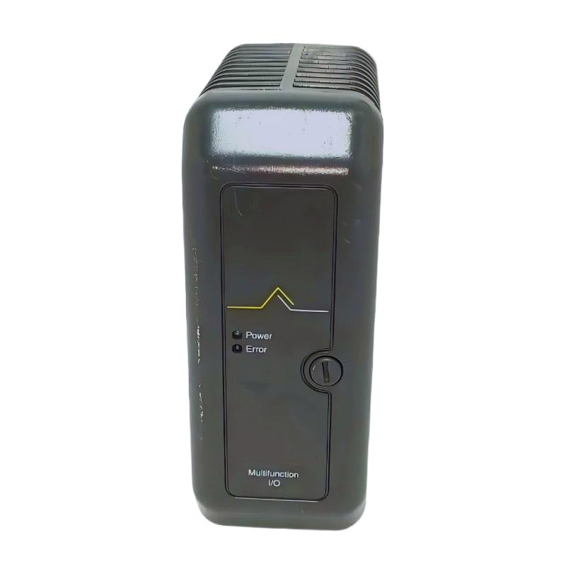
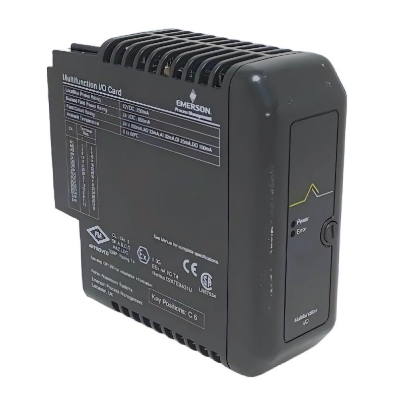
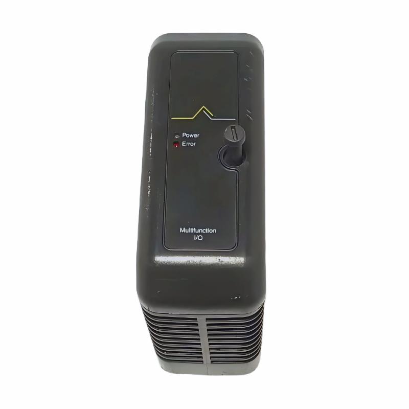
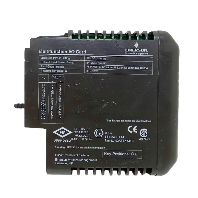
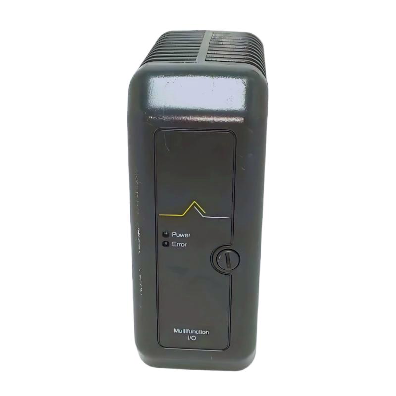
The Emerson VE4015 Pulse Counting Input Card is an industrial automation input component designed to acquire and process pulse-based signals within compatible Emerson process control and distributed control system architectures. It provides an interface between pulse-generating field devices and the control system, allowing discrete pulse information to become part of an automated monitoring, measurement, and control strategy.
Pulse signals are commonly produced by equipment such as flow meters, speed sensors, frequency generators, rotating machinery sensors, and other field instruments. Unlike a conventional analog signal that represents a continuously varying process value, a pulse input represents information through electrical transitions occurring at a defined frequency or count. By detecting these pulses, an automation system can determine events, rotational speed, flow-related information, or other process conditions.
The Emerson VE4015 is identified as a Pulse Counting Input Card and has listed dimensions of 107 × 41 × 105 mm with an approximate weight of 0.36 kg. Its compact design allows it to be integrated into industrial control cabinets together with other Emerson I/O, interface, communication, and controller components.
For replacement and maintenance applications, the complete VE4015 identification, hardware revision, associated terminal arrangement, and host-system compatibility should be verified before installation.
Technical Specifications
| Parameter | Specification |
|---|---|
| Manufacturer | Emerson |
| Model | VE4015 |
| Product Type | Pulse Counting Input Card |
| Product Family | Emerson VE Series |
| Primary Function | Pulse signal acquisition and counting |
| Signal Type | Pulse / frequency-based input |
| Application | Industrial Process Control and Automation |
| Interface Role | Field pulse signal to control-system interface |
| Dimensions | 107 × 41 × 105 mm |
| Weight | 0.36 kg |
| Installation | Compatible Emerson control-system equipment |
| Typical Applications | Flow, speed, counting, frequency and event monitoring |
Exact input electrical characteristics, supported frequency range, channel configuration, threshold levels, isolation characteristics, terminal assignments, and other detailed specifications should be confirmed against the applicable Emerson documentation and hardware revision.
What Is the Emerson VE4015?
The Emerson VE4015 Pulse Counting Input Card is designed to bring pulse-based field information into a compatible industrial control system.
In an automated process, many devices generate signals in the form of electrical pulses. A pulse can represent one event, while the frequency of pulses can represent a continuously changing operating condition.
For example:
- A flow meter may generate pulses proportional to flow.
- A rotational sensor may generate pulses corresponding to shaft movement.
- A speed sensor may produce a frequency proportional to rotational speed.
- A counting device may generate one pulse for every product passing a defined point.
- A process instrument may produce pulse information representing a measured condition.
The VE4015 provides an input interface for this type of signal.
A simplified signal path is:
Field Pulse Device → VE4015 → Control System → Logic / Calculation → HMI or SCADA
The exact application depends on the connected field instrument and control-system configuration.
Pulse Counting Input Principle
Pulse counting is based on detecting changes in an electrical signal.
A typical pulse waveform contains repeated transitions between two electrical states. The input card detects these transitions and provides corresponding information to the control system.
There are two common ways pulse information can be interpreted.
Pulse Count
The system can count the number of detected pulses during a defined measurement period.
For example, if a sensor generates one pulse for every completed mechanical cycle, the accumulated pulse count can represent the number of cycles.
Pulse Frequency
The system can determine how frequently pulses occur.
If the pulse frequency increases, the corresponding process condition may also increase. For example, a rotating machine may generate a higher pulse frequency as shaft speed increases.
A general relationship can be expressed as:
Frequency = Number of Pulses ÷ Measurement Time
The actual engineering calculation depends on the characteristics of the sensor and the application.
Main Functions of the VE4015
Pulse Signal Acquisition
The primary function of the VE4015 is to receive pulse signals from compatible field devices.
The card provides the interface between the external pulse source and the control-system electronics.
Pulse Counting
The input system can be used to count electrical transitions associated with field events.
This is useful for applications involving:
- Product counting
- Machine cycles
- Rotational events
- Meter pulses
- Equipment operation
- Process events
Frequency-Based Measurement
Pulse frequency can also provide information about continuously changing process conditions.
A controller can use frequency information to calculate values such as speed or flow when the sensor’s pulse relationship is known.
Process Monitoring
Pulse information can be incorporated into the control system for monitoring, alarm generation, historical trending, and operational analysis.
Integration With Control Logic
Once the pulse information is available to the control architecture, the controller can use it in programmed calculations and control strategies.
Pulse Counting in Industrial Automation
Pulse counting provides a useful alternative to traditional analog measurement when the field instrument naturally produces a digital pulse output.
Consider a rotating machine equipped with a pulse-generating sensor.
The general measurement sequence is:
Rotating Equipment → Pulse Sensor → VE4015 → Control Processor → Speed Calculation → Operator Display
If the sensor generates a known number of pulses per revolution, the controller can determine rotational speed from the measured pulse frequency.
Similarly, a pulse-output flow meter can provide flow-related information based on the number or frequency of pulses generated by the meter.
This makes pulse-counting inputs useful in applications where event frequency itself carries process information.
Role in Process Control Systems
The VE4015 can serve as part of the input layer of an industrial automation system.
A typical architecture may include:
Process Equipment
↓
Pulse Sensor / Pulse-Output Instrument
↓
VE4015 Pulse Counting Input Card
↓
Control Processor
↓
Control Logic / Calculations
↓
HMI / SCADA / Historian
This arrangement allows pulse information to be converted into useful process data.
For example, a controller may use pulse information to:
- Calculate equipment speed
- Count production units
- Monitor machine cycles
- Detect equipment operation
- Calculate flow
- Trigger alarms
- Monitor process events
- Generate maintenance information
The exact implementation depends on the control application.
Industrial Applications
Flow Measurement
Some flow meters provide pulse outputs rather than conventional analog signals.
The VE4015 can provide an interface for compatible pulse-output flow instrumentation, allowing the control system to use pulse information for flow calculations and monitoring.
Rotational Speed Monitoring
Rotating machinery can generate pulses through proximity sensors, magnetic pickups, encoders, or other compatible sensing devices.
Pulse frequency can then be associated with shaft speed.
Typical equipment includes:
- Pumps
- Fans
- Compressors
- Turbines
- Motors
- Rotating process equipment
Production Counting
Manufacturing systems often need to count products or machine cycles.
A pulse-generating sensor can generate an event each time a product passes a detection point.
The control system can then use the accumulated count for production monitoring and sequencing.
Packaging Machinery
Packaging equipment frequently contains sensors that generate pulses as products, containers, or machine cycles move through the production line.
Pulse counting can therefore be used for machine synchronization and production monitoring.
Conveyor Systems
Conveyor applications may use pulse-generating sensors to monitor belt movement, shaft rotation, product counts, or operating cycles.
Utility Equipment
Pulse-output meters and monitoring devices can be used in utility systems where consumption or equipment operation needs to be monitored.
System Integration
The VE4015 should be integrated as part of a complete control architecture rather than operated as a standalone controller.
A typical arrangement can include:
| System Layer | Typical Function |
|---|---|
| Field Sensor | Generates pulse signal |
| Signal Cable | Transfers pulse information |
| VE4015 | Acquires pulse input |
| Control Processor | Processes input information |
| Control Logic | Performs calculations and decisions |
| HMI | Displays operating information |
| SCADA | Provides supervisory monitoring |
| Historian | Stores process data |
The quality of the final measurement depends on the entire signal chain.
A correctly installed input card cannot compensate for an unsuitable sensor, damaged cable, incorrect wiring, or an improperly configured control system.
Installation Guidelines
Verify Product Identification
Before installation, confirm:
- VE4015 model number
- Hardware revision
- Existing board markings
- Installation position
- Associated terminal hardware
- Host-system configuration
- Field-device connection
The complete product identification should be checked before replacement.
Power Isolation
Follow the plant’s approved electrical isolation and lockout procedures before removing or installing the card.
Inspect Connectors
Check connectors for:
- Bent contacts
- Corrosion
- Contamination
- Loose connections
- Mechanical damage
- Heat-related discoloration
Verify Field Wiring
Pulse signals can be affected by incorrect wiring or electrical interference.
Verify the field cable routing and termination against the approved system wiring documentation.
Pulse Signal Wiring Considerations
Reliable pulse acquisition depends on maintaining signal integrity.
Cable Routing
Pulse signal wiring should be routed appropriately and separated from high-power switching conductors where practical.
Shielding
Where required by the system design, suitable shielding can help reduce electromagnetic interference.
Grounding
The grounding arrangement should follow the electrical design of the installed Emerson control system.
Connection Security
Loose terminals or connectors can produce intermittent pulse detection and inaccurate counts.
Sensor Compatibility
The connected pulse source must be electrically compatible with the input interface. Do not assume that every pulse-generating sensor can be connected directly without verifying the required interface characteristics.
Commissioning Procedure
After installation, the VE4015 should be commissioned systematically.
Step 1: Confirm Hardware
Verify the VE4015 identification and correct installation position.
Step 2: Check Connections
Inspect all relevant card, terminal, and field-device connections.
Step 3: Verify Sensor Operation
Confirm that the pulse-generating field device is operating correctly.
Step 4: Check Input Recognition
Verify that the control system receives the expected pulse information.
Step 5: Confirm Counting
Operate the associated equipment and verify that the control system registers the expected number of events.
Step 6: Check Frequency
Where frequency measurement is used, compare the displayed value against an appropriate reference.
Step 7: Verify Control Logic
Confirm that calculations, alarms, interlocks, and control functions respond correctly to the pulse input.
Step 8: Monitor During Operation
Observe the system under normal operating conditions to confirm stable pulse acquisition.
Troubleshooting the Emerson VE4015
Troubleshooting should consider the sensor, wiring, input card, configuration, and control logic as one complete system.
No Pulse Detected
Possible causes include:
- Sensor not operating
- Incorrect wiring
- Loose connector
- Damaged cable
- Incorrect input configuration
- Lack of sensor power
- Input interface problem
- VE4015 hardware fault
The field sensor should be tested before concluding that the input card has failed.
Incorrect Pulse Count
An incorrect count may result from:
- Electrical noise
- Incorrect sensor installation
- Missed pulses
- False triggering
- Incorrect signal configuration
- Damaged wiring
- Poor connections
- Incorrect control-system calculation
Compare the actual field events with the value registered by the control system.
Unstable Frequency Reading
An unstable frequency value can be associated with:
- Sensor instability
- Electrical interference
- Mechanical vibration
- Poor cable routing
- Loose wiring
- Inconsistent equipment speed
- Signal-conditioning issues
The physical process should be checked before replacing electronic hardware.
Count Stops Unexpectedly
If counting suddenly stops, inspect:
- Field sensor
- Sensor power
- Cable continuity
- Terminal connections
- VE4015 seating
- System diagnostics
- Input configuration
- Control logic
This approach helps distinguish field-device problems from interface-card problems.
Preventive Maintenance
Regular maintenance helps preserve reliable pulse measurement.
Inspect Sensors
Check pulse-generating sensors for contamination, mechanical damage, incorrect alignment, and deterioration.
Inspect Cables
Look for damaged insulation, loose connections, excessive bending, and environmental deterioration.
Check Connectors
Ensure that card and terminal connections remain secure.
Monitor Pulse Trends
Unexpected changes in pulse frequency can provide early indications of changes in machine speed, flow, or other monitored conditions.
Maintain Cabinet Conditions
Protect electronic equipment from excessive dust, moisture, heat, and vibration.
Review Diagnostic History
Recurring input faults should be recorded and investigated to identify underlying problems.
Replacement Considerations
When replacing an Emerson VE4015 Pulse Counting Input Card, verify the complete product identification before ordering or installing the replacement.
Important information includes:
- Model: VE4015
- Product Type: Pulse Counting Input Card
- Hardware revision
- Board markings
- Installation position
- Connector configuration
- Associated terminal hardware
- Host control-system configuration
The listed physical specifications are:
Dimensions: 107 × 41 × 105 mm
Weight: 0.36 kg
Physical dimensions alone should not be used to determine interchangeability.
A card with a similar mechanical form factor may have a completely different signal function or electrical interface.
Cabinet Installation and Space Planning
The VE4015 has a listed size of 107 × 41 × 105 mm.
Its compact dimensions allow it to be installed within industrial automation cabinets alongside other control-system components.
When planning installation, engineers should account for:
- Module insertion and removal space
- Field wiring
- Terminal access
- Cable bending radius
- Heat dissipation
- Neighboring modules
- Maintenance access
Good cabinet organization helps reduce wiring errors and makes future troubleshooting easier.
Compatible System Components
The VE4015 may form part of an industrial pulse-measurement system containing several categories of components.
| Component | Typical Function |
|---|---|
| Pulse Sensor | Generates electrical pulses |
| Flow Meter | Provides pulse-based flow information |
| Speed Sensor | Generates rotational-speed pulses |
| Proximity Sensor | Detects machine or product events |
| VE4015 | Pulse counting input interface |
| I/O / Terminal Hardware | Field signal connection |
| Control Processor | Executes calculations and logic |
| HMI | Displays pulse-related process information |
| SCADA System | Supervisory monitoring |
| Historian | Stores operating data |
Exact compatibility depends on the Emerson system architecture and electrical requirements of the connected field device.
Related Emerson Models
The Emerson VE family includes various I/O, communication, interface, and control components.
| Model | Product Type | General Role |
|---|---|---|
| VE3005 | Controller MD Module | Control-system processing |
| VE3006 | Digital Input Module | Digital signal acquisition |
| VE4002 Series | Digital Output Hardware | Discrete output control |
| VE4003 Series | Analog Input Hardware | Analog measurement |
| VE4005 Series | Analog Output Hardware | Analog process output |
| VE4006P | Serial Interface Module | Serial communication |
| VE4007 | Fieldbus Card | Fieldbus integration |
| VE4009 | ASI Interface Card | ASI interface |
| VE4010 Series | Digital Input Hardware | Discrete input processing |
| VE4011 Series | Digital Output Hardware | Digital output processing |
| VE4012 Series | Analog Input Hardware | Analog input acquisition |
| VE4013 Series | Input Hardware | Process input interface |
| VE4014 | PROFIBUS DP Interface Module | Digital fieldbus communication |
| VE4015 | Pulse Counting Input Card | Pulse and frequency input acquisition |
These products should not automatically be treated as interchangeable. Compatibility should be confirmed using the complete model designation and host-system requirements.
Engineering Best Practices
Match the Sensor to the Input Interface
Before connecting a pulse sensor, verify that its electrical output is suitable for the installed input system.
Minimize Electrical Noise
Keep pulse wiring away from high-current switching circuits wherever practical.
Validate Counting Accuracy
During commissioning, compare the system count with a known number of field events.
Monitor Long-Term Trends
Trend pulse frequency and accumulated counts where these values represent important process conditions.
Maintain Accurate Documentation
Keep current wiring diagrams, sensor specifications, control-system configurations, and module identification records.
Keep an Identified Spare
For critical applications, an appropriately identified VE4015 spare can help reduce downtime during hardware replacement.
Key Advantages
The Emerson VE4015 offers practical benefits for industrial pulse-based measurement applications:
- Dedicated pulse counting input functionality
- Suitable for industrial process automation
- Supports pulse-based event monitoring
- Can support frequency-related measurements
- Compact 107 × 41 × 105 mm construction
- Approximate weight of 0.36 kg
- Integrates pulse-generating field devices with compatible control systems
- Suitable for distributed automation architectures
- Supports applications involving speed, flow, counting, and machine events
- Designed for modular industrial control-system integration
Technical FAQs
What is the Emerson VE4015?
The Emerson VE4015 is a Pulse Counting Input Card designed to acquire pulse-based signals within compatible Emerson industrial automation systems.
What does the VE4015 measure?
The card is intended for pulse-based input applications. Depending on the connected sensor and control-system configuration, pulse information can be used for event counting, frequency measurement, speed monitoring, flow calculations, and related process functions.
What are the dimensions of the VE4015?
The listed dimensions are 107 × 41 × 105 mm.
How much does the VE4015 weigh?
The listed weight is approximately 0.36 kg.
What types of devices can generate signals for a pulse counting input?
Potential sources include compatible flow meters, speed sensors, proximity sensors, rotating-machine sensors, production counters, and other pulse-output field instruments.
Is the VE4015 an analog input card?
No. The VE4015 is identified as a Pulse Counting Input Card, intended for pulse-based signal acquisition rather than conventional analog measurement.
Can pulse frequency be used to calculate speed?
Yes, when the relationship between sensor pulses and mechanical rotation is known, pulse frequency can be used by the control system to calculate rotational speed.
Can the VE4015 be used for flow measurement?
It can be used in compatible systems where a flow instrument provides a pulse output and the control application is configured to convert the pulse information into a flow-related value.
What causes missed pulses?
Possible causes include electrical interference, poor sensor installation, damaged cables, loose connections, unsuitable signal characteristics, or configuration problems.
What should be checked before replacing the VE4015?
Verify the complete model number, hardware revision, connector arrangement, installation position, associated terminal hardware, field-device requirements, and host-system configuration.
Can another Emerson VE-series card replace the VE4015?
Not automatically. A replacement must provide the required pulse-input function and be compatible with the specific Emerson control architecture.
Conclusion
The Emerson VE4015 Pulse Counting Input Card is a specialized industrial automation component designed to acquire pulse-based information from compatible field devices. By bringing pulse signals into the control architecture, the module can support applications involving event counting, machine-speed monitoring, flow measurement, production counting, and other frequency-based process measurements.
The VE4015 has listed dimensions of 107 × 41 × 105 mm and a weight of approximately 0.36 kg, providing a compact solution for industrial control cabinets and modular process-control installations.
Its performance depends on the complete measurement chain, including the pulse-generating sensor, field wiring, interface hardware, control-system configuration, and application logic. Correct sensor selection, proper wiring, appropriate installation, and systematic commissioning are therefore essential for reliable pulse acquisition.
For maintenance and replacement, the complete Emerson VE4015 identification should be verified before installation. Physical dimensions alone are not sufficient to establish compatibility, and the applicable hardware revision and host-system configuration should always be checked.