

ProductPRODUCT
Featured products



Contact Us
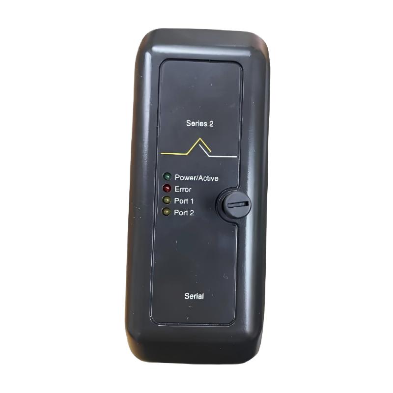
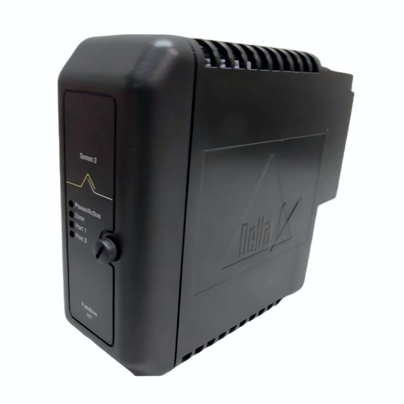
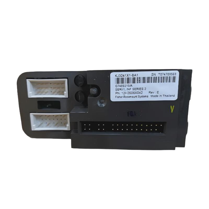
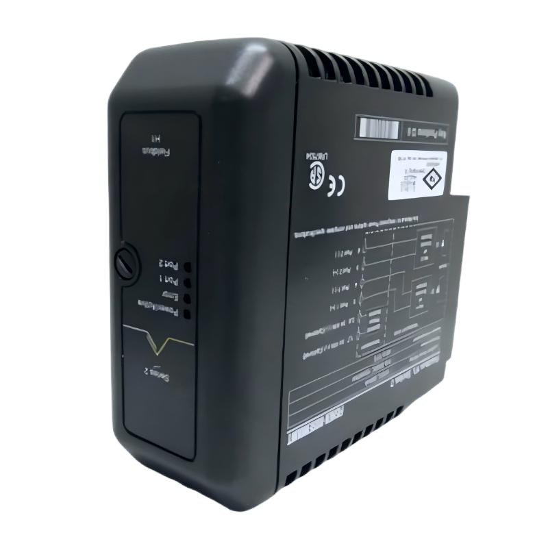
- Emerson
- VE4011B1
- Digital Output Module
- USA
- 107 x 41 x 105 mm
- 0.22 kg
- Xiamen, China
- New & In Stock
- T/T, PayPal, Western Union
- 1 Year
- 1-3 Working Days
- DHL, UPS, TNT, FedEx and EMS.
- 24-Hour Service
- COO
- 35
Our advantage

Global Logistics
We have a 10-year logistics and express cooperation agreement, so our products can be shipped to any place in the world.

Brand new and original
Our products are imported in bulk from the place of origin. Because of the cooperative relationship, our products are all original and 100% new.

24-hour service
We provide 7*24 hours service to our customers. We will be there whenever you need us.

Price advantage
All our products are priced very favorably because we have our own warehouse and supply.
| Company Information | |||
| [email protected] | |||
| Mobile | +8615980777398 | ||
| +8615980777398 | |||
| 15980777398 |
Product Overview
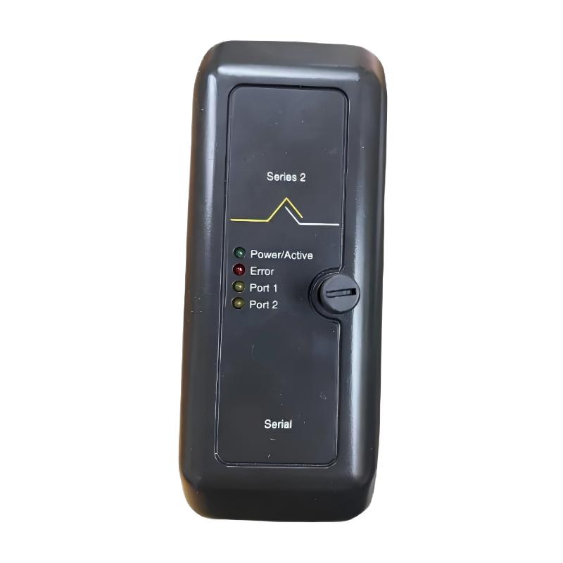
The Emerson VE4011B1 Digital Output Module is an industrial automation interface component designed to provide discrete output signals from a compatible Emerson control system to field devices. As part of an industrial process-control architecture, the module can be used to translate controller commands into discrete electrical states for operating or controlling compatible field equipment.
Digital output functions are fundamental to automated industrial systems. A controller may determine that a pump should start, a valve should change position, an actuator should operate, or an alarm device should be activated. The corresponding digital output signal provides the interface between the programmed control logic and the physical equipment.
The Emerson VE4011B1 is therefore suited to applications where reliable ON/OFF control signals are required. Depending on the system configuration, digital outputs can participate in equipment control, sequencing, permissive logic, alarm functions, interlocking, and process automation.
The module has listed dimensions of 107 × 41 × 105 mm and a weight of approximately 0.22 kg. Its compact form factor makes it suitable for control cabinets and distributed I/O assemblies where multiple automation modules must be installed efficiently.
Exact electrical output characteristics, channel configuration, output ratings, isolation, terminal assignments, and supported field-device types should be verified against the applicable Emerson documentation and the specific hardware revision before installation.
Technical Specifications
| Parameter | Specification |
|---|---|
| Manufacturer | Emerson |
| Model | VE4011B1 |
| Product Type | Digital Output Module |
| Functional Category | Discrete Output |
| Primary Function | Digital control signal output |
| Signal Type | Digital / Discrete Output |
| Application | Industrial Process Automation |
| Interface Role | Control-system output to field-device interface |
| Dimensions | 107 × 41 × 105 mm |
| Weight | 0.22 kg |
| Installation | Compatible Emerson control-system equipment |
| Typical Applications | Valve control, actuator control, equipment commands, alarms, sequencing |
Note: Exact output voltage, output current, channel count, load type, isolation characteristics, protection functions, and terminal configuration should be confirmed against the applicable VE4011B1 documentation and installed system configuration.
What Is the Emerson VE4011B1?
The VE4011B1 Digital Output Module is an industrial control-system component used to provide discrete electrical commands to compatible field devices.
In an automated process, the controller does not directly operate every field device. Instead, the controller generates commands that pass through appropriate I/O hardware before reaching the field equipment.
A simplified control path is:
Controller → VE4011B1 → Field Wiring → Actuator / Valve / Relay → Process Equipment
The digital output normally represents a discrete state such as:
OFF → ON
or:
Inactive → Active
The receiving field device interprets the output according to its design.
Examples include commands for:
- Motor starters
- Solenoid valves
- Relays
- Contactors
- Actuators
- Indicator devices
- Alarm circuits
- Other compatible discrete loads
The exact load compatibility must be checked against the electrical specifications of the installed system.
Digital Output Working Principle
A digital output module converts a control-system command into an appropriate discrete output state.
When application logic determines that a field device should operate, the controller sends the corresponding command to the output interface.
The basic process can be represented as:
Control Logic → Output Command → VE4011B1 → Field Device → Physical Action
For example, consider a process pump controlled by a discrete command.
- The controller determines that the pump should run.
- The digital output is commanded to its active state.
- The VE4011B1 provides the corresponding output signal.
- The external control circuit receives the signal.
- The pump-control equipment responds.
- The process changes accordingly.
The same principle can be applied to valves, actuators, relays, alarms, and other discrete equipment.
Function and Signal Processing
Controller Command Reception
The control system generates an output state based on programmed logic.
This logic may depend on:
- Operator commands
- Process conditions
- Equipment status
- Interlocks
- Permissives
- Timers
- Sequence steps
- Alarm conditions
Digital State Conversion
The VE4011B1 provides the corresponding discrete output interface.
The module’s job is not to determine the process strategy. Instead, it provides the hardware pathway through which the controller’s command can be delivered to the appropriate field circuit.
Field Device Operation
The output signal is transferred through the associated wiring to the controlled device.
Depending on the application, the receiving device may be:
- A relay
- A solenoid
- A contactor interface
- An actuator
- A valve-control circuit
- An indicator
- An alarm device
Feedback and Verification
Digital output control is frequently combined with digital input feedback.
For example:
Output Command → Valve Opens → Position Switch → Digital Input → Controller
This creates a basic command-and-confirmation architecture.
The controller can compare the command with actual equipment feedback and generate an alarm if the expected response does not occur.
Role in Industrial Automation
The VE4011B1 can occupy the output layer between the Emerson controller and field equipment.
A typical automation architecture includes:
Process → Sensors / Field Devices → I/O → Controller → I/O → Actuators → Process
The VE4011B1 participates on the output side of this architecture.
Its digital output signals can be used to control equipment according to programmed logic.
This is particularly important in sequential processes where equipment must operate in a defined order.
For example:
Start Command → Pump Start → Valve Position → Process Operation → Shutdown Command
Each stage may depend on digital outputs and corresponding feedback signals.
Industrial Applications
Valve Control
Digital outputs can be used to command compatible valve-control circuits.
Typical applications include:
- Open commands
- Close commands
- Solenoid activation
- Actuator control
- Process isolation
- Sequence control
The exact output circuit must be matched to the valve actuator and its electrical requirements.
Pump and Motor Control
A digital output can provide a control command to an external motor-control circuit.
The output may initiate:
- Pump startup
- Pump shutdown
- Motor starter operation
- Enable signals
- Equipment permissive functions
The VE4011B1 should not be assumed to directly switch a motor unless the electrical design specifically permits it. In many industrial installations, the digital output operates an intermediate relay, starter, or control interface.
Process Sequencing
Industrial processes often require equipment to operate in a predefined sequence.
Digital outputs can control:
- Pumps
- Valves
- Solenoids
- Actuators
- Mechanical devices
- Auxiliary equipment
The controller determines when each output becomes active.
Alarm and Indication Systems
Compatible output circuits may also be used to activate:
- Warning devices
- Audible alarms
- Indicator lamps
- External alarm interfaces
Material Handling
Discrete outputs can provide commands to conveyors, gates, diverters, and other automated material-handling equipment through appropriate interface circuits.
Manufacturing Automation
Production machinery commonly uses digital commands for actuators, clamps, solenoids, relays, and other discrete devices.
System Integration
The VE4011B1 is normally integrated into a larger control-system architecture rather than operating as an independent device.
A simplified structure is:
Operator / SCADA → Controller → VE4011B1 → Field Device → Process
The controller executes the application logic and determines the desired output state.
The VE4011B1 provides the output interface.
The field device converts the electrical command into a physical action.
Feedback may then return through an input module:
Field Device → Digital Input → Controller
This closed-loop architecture allows the control system to verify whether commanded equipment has actually reached the required condition.
Installation Guidelines
Verify Module Identification
Before installation, confirm:
- Model: VE4011B1
- Product type: Digital Output Module
- Hardware revision
- Installation location
- Associated terminal equipment
- Host Emerson system
Physical similarity between I/O modules should not be used as proof of compatibility.
Check Output Circuit Requirements
Before connecting a field device, verify that its electrical requirements are compatible with the output interface.
Important considerations include:
- Output voltage
- Load current
- Load type
- Switching characteristics
- External relay requirements
- Protection requirements
Exact values should be taken from the applicable Emerson documentation.
Inspect Field Wiring
Check the output wiring for:
- Loose terminals
- Damaged insulation
- Incorrect connections
- Moisture
- Corrosion
- Mechanical stress
- Incorrect routing
Confirm Load Compatibility
The connected device should be suitable for the output circuit.
For higher-power equipment, an intermediate relay, contactor, starter, or other interface may be required rather than connecting the load directly to the module.
Commissioning Procedure
A structured commissioning process helps prevent wiring and configuration problems.
Step 1: Verify Installation
Confirm that the VE4011B1 is correctly installed and securely connected.
Step 2: Check Wiring
Compare field wiring with the approved system documentation.
Step 3: Verify Output Configuration
Confirm that the controller configuration corresponds to the physical output assignment.
Step 4: Test Individual Outputs
Activate outputs under controlled conditions and observe the associated field devices.
Step 5: Verify Equipment Response
Confirm that the commanded device responds correctly.
Step 6: Test Interlocks
Where applicable, verify that interlock and permissive logic prevents inappropriate operation.
Step 7: Check Feedback
If equipment provides status feedback, verify that the controller receives the expected input signal.
Step 8: Record Results
Document output assignments, connected equipment, tested conditions, and commissioning results.
Troubleshooting the VE4011B1
Digital output faults should be investigated through the entire control path.
Output Does Not Activate
If an expected field device does not respond, inspect:
- Controller output command
- Output configuration
- VE4011B1 installation
- Module connections
- Field wiring
- External relay or interface
- Field-device condition
- System diagnostics
The problem may occur outside the output module.
Output Remains Active
If a field device remains energized unexpectedly, investigate:
- Controller logic
- Manual override
- Output configuration
- Wiring
- External relay contacts
- Field-device condition
Do not immediately assume that the output module has failed.
Intermittent Output
Intermittent operation may be caused by:
- Loose connections
- Wiring damage
- Relay problems
- Mechanical vibration
- Configuration issues
- Field-device problems
- Electrical interference
Observe both the controller command and the physical output circuit when troubleshooting.
Output Works but Equipment Does Not Respond
If the control system shows an active output but the field device does not operate, inspect the downstream circuit.
Possible causes include:
- Open wiring
- Failed relay
- Failed solenoid
- Incorrect external power
- Mechanical obstruction
- Incompatible load
- Field-device failure
This distinction is important because an apparently correct software command does not necessarily mean that the physical equipment has received or acted upon the signal.
Multiple Outputs Fail
If several outputs fail simultaneously, inspect common system elements first.
Potential causes include:
- Shared power supply
- Common wiring
- I/O infrastructure
- Controller configuration
- System communication
- Common protection devices
A common-cause problem can affect several output channels at once.
Preventive Maintenance
Regular inspection can improve the reliability of digital output systems.
Inspect Output Wiring
Check field cables and terminals for damage, looseness, corrosion, and moisture.
Check External Interface Devices
If relays, contactors, or interface modules are used, inspect them for contact wear or abnormal operation.
Monitor Equipment Feedback
Compare output commands with actual equipment status where feedback is available.
Review Diagnostics
Use available controller and I/O diagnostics to identify abnormal output behavior.
Maintain Cabinet Conditions
Keep the control cabinet clean and protected from excessive heat, moisture, dust, and vibration.
Physical Dimensions and Weight
The Emerson VE4011B1 Digital Output Module has the following listed physical characteristics:
| Mechanical Parameter | Value |
|---|---|
| Dimensions | 107 × 41 × 105 mm |
| Weight | 0.22 kg |
The compact dimensions allow the module to be integrated into industrial automation cabinets with multiple I/O assemblies.
Cabinet planning should also account for wiring, connectors, cable bending radius, maintenance access, and adjacent equipment.
The listed module weight of 0.22 kg can be useful for spare-parts management, shipping planning, and equipment inventory.
Signal Wiring and Engineering Considerations
Reliable digital output operation depends on correct electrical and mechanical installation.
Separate Signal and Power Circuits
Where appropriate, output wiring should be routed separately from high-power conductors to reduce interference.
Use Appropriate Interface Devices
Higher-power loads should normally be controlled through properly selected intermediate switching devices where required.
Document Output Assignments
Each output should have clear documentation identifying:
- Controller tag
- Physical output
- Field device
- Equipment function
- Normal state
- Safe state where applicable
Verify Fail-State Behavior
For critical equipment, engineers should determine what the controlled device should do if the output becomes unavailable or the control system loses power.
Test the Complete Circuit
Commissioning should verify not only the controller indication but also the physical response of the field equipment.
Compatible System Components
The VE4011B1 can form part of a larger Emerson process automation system containing multiple functional layers.
| Component | Typical Function |
|---|---|
| Emerson Controller | Executes control logic |
| VE4011B1 | Provides digital output signals |
| Terminal / Interface Hardware | Connects field circuits |
| Relay or Contactor | Provides additional switching/interface capability |
| Solenoid Valve | Converts electrical command into valve action |
| Actuator | Performs mechanical movement |
| Digital Input Module | Provides equipment-status feedback |
| HMI | Displays process and equipment status |
| SCADA | Provides supervisory monitoring |
| Field Equipment | Performs the required process function |
The exact combination depends on the host system and application.
Related Emerson Models
| Model / Family | Product Type | General Function |
|---|---|---|
| VE3006 | Digital Input Module | Discrete signal acquisition |
| VE4002 | Discrete Output Module | Digital equipment control |
| VE4003 | Analog Input Module | Analog process measurement |
| VE4005 | Analog Output Module | Analog control output |
| VE4006P | Serial Interface Module | Serial communication |
| VE4007 | Fieldbus Card | Industrial field communication |
| VE4009 | ASI Interface Card | ASI field-device interface |
| VE4010B1 | IS DI Module | Discrete input acquisition |
| VE4011B1 | Digital Output Module | Discrete output control |
These products may be used within related Emerson automation architectures, but they should not automatically be considered interchangeable. Exact compatibility should be verified using the required function, electrical characteristics, hardware revision, and host-system configuration.
Engineering Best Practices
For reliable operation of the Emerson VE4011B1, engineers and maintenance personnel should:
- Verify the complete module identification before installation.
- Confirm output electrical compatibility with the connected load.
- Use appropriate intermediate switching devices where required.
- Maintain clear field-wiring documentation.
- Separate output wiring from high-power conductors where practical.
- Test output commands during commissioning.
- Verify actual equipment response rather than relying only on controller status.
- Check feedback signals where available.
- Inspect relays, contactors, and field devices periodically.
- Maintain suitable control-cabinet environmental conditions.
A complete end-to-end approach is generally more effective than troubleshooting the output module in isolation.
Key Advantages
Dedicated Digital Output Function
The VE4011B1 provides a dedicated interface for transferring discrete control commands from an Emerson automation system to compatible field equipment.
Compact Design
With listed dimensions of 107 × 41 × 105 mm, the module is suitable for space-conscious industrial control cabinets.
Supports Automated Equipment Control
Digital outputs can participate in automatic control of valves, actuators, relays, solenoids, and other compatible discrete devices.
Useful for Sequential Control
Output signals can be incorporated into automated process sequences, permissives, interlocks, and equipment-control strategies.
Supports Process Automation
The module can form part of an integrated architecture connecting controllers with field-level equipment.
Technical FAQs
What is the Emerson VE4011B1?
The Emerson VE4011B1 is a Digital Output Module designed to provide discrete output signals from a compatible Emerson control system to field equipment.
What is the primary function of a digital output module?
A digital output module transfers discrete commands from the control system to compatible field devices. These commands can be used for equipment operation, sequencing, alarms, interlocks, and other automation functions.
What are the dimensions of the VE4011B1?
The listed dimensions are 107 × 41 × 105 mm.
How much does the VE4011B1 weigh?
The listed weight is approximately 0.22 kg.
What devices can be controlled by a digital output?
Depending on the electrical design, digital outputs can interface with relays, solenoids, actuators, valve-control circuits, indicators, contactor interfaces, and other compatible discrete loads.
Can the VE4011B1 directly control a motor?
A digital output should not automatically be connected directly to a motor. Motors typically require dedicated switching and protection equipment. The VE4011B1 may instead provide a command to an appropriate motor-control interface when the system is designed that way.
What causes a digital output to fail?
Potential causes include controller configuration errors, wiring problems, power issues, failed external relays, incompatible loads, loose connections, field-device faults, or module-level problems.
Why does an output show ON while the equipment remains OFF?
The controller may be commanding the output correctly while the problem exists downstream. Field wiring, external relays, power supplies, solenoids, contactors, or the controlled equipment should therefore be checked.
Can another Emerson output module replace the VE4011B1?
Not automatically. Replacement requires verification of the module function, electrical output characteristics, hardware revision, terminal arrangement, and compatibility with the host Emerson control system.
How should the VE4011B1 be maintained?
Maintenance should include inspection of output wiring, connectors, external switching devices, field equipment, controller diagnostics, and cabinet environmental conditions. Periodic functional testing is also useful for critical output circuits.
Conclusion
The Emerson VE4011B1 Digital Output Module is an industrial automation interface component designed to deliver discrete control signals from a compatible Emerson control system to field equipment. By providing the output layer between controller logic and physical devices, it can support valve control, actuator operation, equipment commands, alarms, interlocks, and automated process sequencing.
With listed dimensions of 107 × 41 × 105 mm and a weight of 0.22 kg, the VE4011B1 provides a compact solution for industrial control-system installations where efficient cabinet organization and reliable field interfacing are important.
For installation and replacement, the complete VE4011B1 identification should be verified together with the applicable hardware revision and system configuration. Output voltage, current capacity, channel arrangement, load compatibility, terminal assignments, and other electrical characteristics should be confirmed before connecting field equipment.
Reliable operation ultimately depends on the complete signal path: controller logic, VE4011B1 output interface, wiring, external switching equipment, and field device. Systematic commissioning, correct wiring, preventive maintenance, and end-to-end troubleshooting can help maintain stable digital output control in demanding industrial automation environments.