

ProductPRODUCT
Featured products

Contact Us
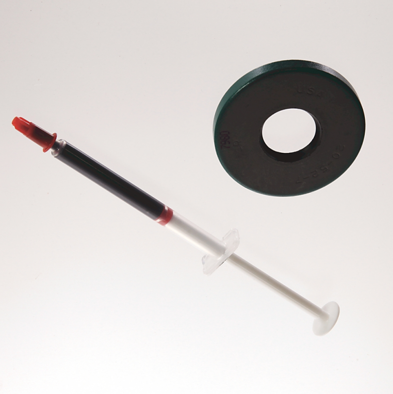
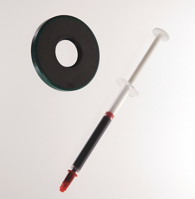
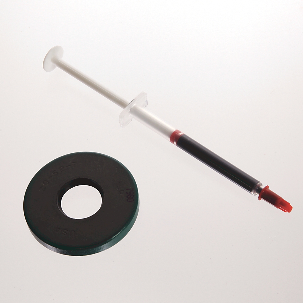
- Allen Bradley
- MPL-SSN-F165-32MM
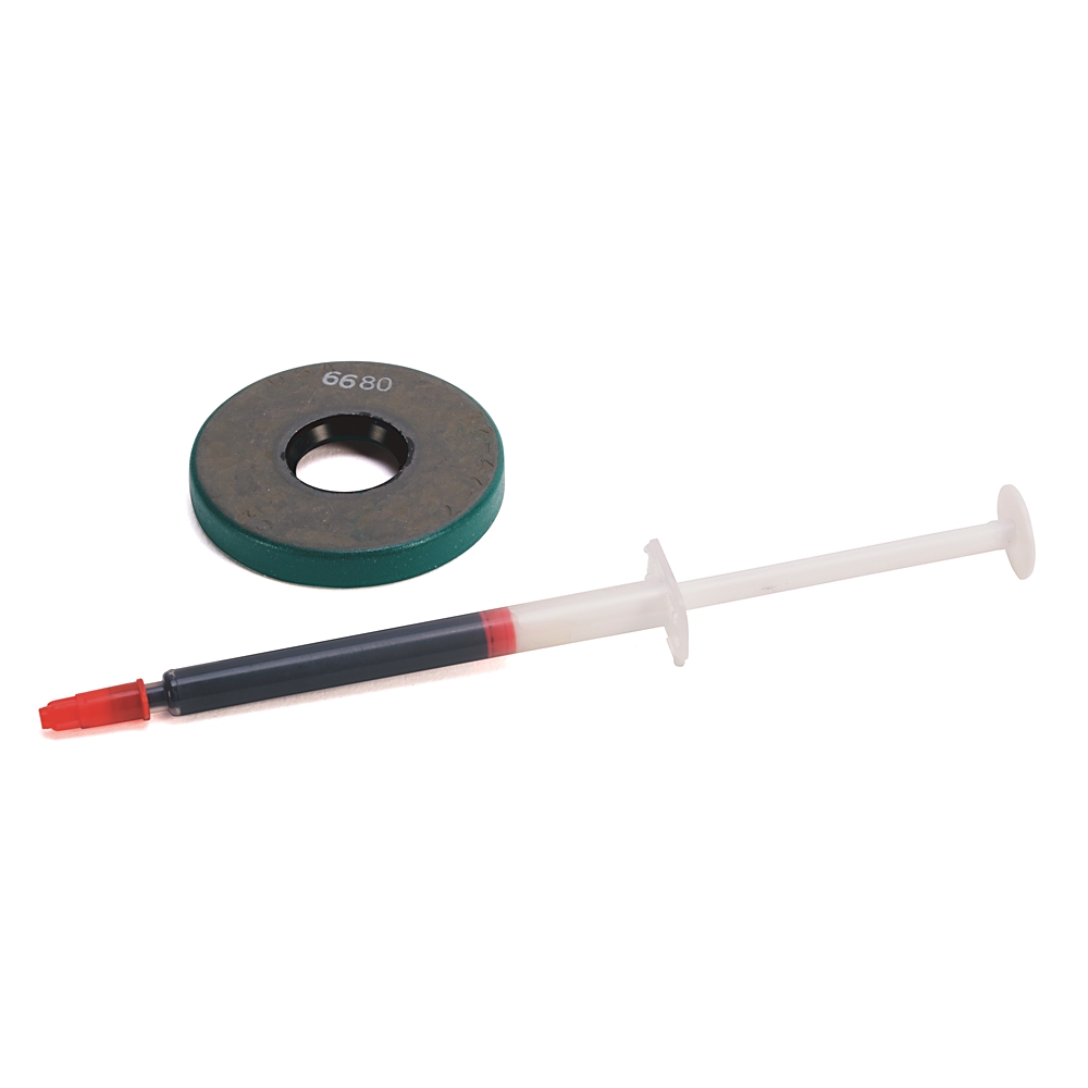
- Seal Sealing Kit for Use with Motor Accessories
- USA
- 35 × 100 × 110 mm
- 0.3kg
- Xiamen, China
- New & In Stock
- T/T, PayPal, Western Union
- 1 Year
- 1-3 Working Days
- DHL, UPS, TNT, FedEx and EMS.
- 24-Hour Service
- COO
- 6
Our advantage

Global Logistics
We have a 10-year logistics and express cooperation agreement, so our products can be shipped to any place in the world.

Brand new and original
Our products are imported in bulk from the place of origin. Because of the cooperative relationship, our products are all original and 100% new.

24-hour service
We provide 7*24 hours service to our customers. We will be there whenever you need us.

Price advantage
All our products are priced very favorably because we have our own warehouse and supply.
| Company Information | |||
| [email protected] | |||
| Mobile | +8615980777398 | ||
| +8615980777398 | |||
| 15980777398 |
Allen-Bradley MPL-SSN-F165-32MM — Product Specifications, Features, Applications and Model Recommendations
1. Product Overview
The Allen-Bradley MPL-SSN-F165-32MM is a model designation associated with the MPL family of low-inertia servo motors. The MPL series is designed for precision motion control systems that require accurate positioning, controlled acceleration and deceleration, repeatable motion, and reliable operation in automated production environments.
Servo motors in this category are commonly used in applications where a machine must move a load to a specified position, maintain a commanded speed, or regulate torque while responding to changing operating conditions. Typical examples include packaging equipment, automated assembly lines, material handling machinery, machine tools, and precision manufacturing systems.
The MPL family is generally associated with compact motor construction, low rotor inertia, high dynamic response, and integration into industrial servo drive systems. These characteristics make the series suitable for applications requiring frequent starts and stops, rapid direction changes, and coordinated movement across multiple machine axes.
The exact electrical ratings, mechanical dimensions, shaft configuration, feedback device, connector arrangement, and mass of the specific MPL-SSN-F165-32MM model should be confirmed against its complete manufacturer part number and nameplate. The model designation alone does not establish every technical specification, so unverified numerical ratings should not be treated as guaranteed product data.
This profile is written in English for technical product catalogues, industrial procurement documentation, equipment selection, and engineering reference purposes. It distinguishes established characteristics of the MPL motor family from model-specific information that requires verification.
2. Brand and Product Series
|
Item |
Product information |
|---|---|
|
Brand |
Allen-Bradley |
|
Product model |
MPL-SSN-F165-32MM |
|
Product category |
Industrial servo motor |
|
Product family |
MPL servo motor family |
|
Typical system |
Servo motor, compatible servo drive, feedback system, and motion controller |
|
Primary function |
Controlled rotary motion |
|
Main operating objectives |
Position control, speed regulation, torque control, and dynamic motion response |
|
Typical installation |
Industrial machinery and automated production equipment |
|
Control method |
Closed-loop servo control when used with a compatible feedback and drive system |
|
Mechanical configuration |
Exact shaft, mounting, and connector details require model-specific confirmation |
|
Dimensions |
Exact overall dimensions require the corresponding mechanical drawing |
|
Weight (kg) |
Exact model weight requires confirmation from the product datasheet or shipping-free mechanical specification |
Allen-Bradley is an industrial automation brand known for motion control, motor control, programmable controllers, and related factory automation equipment. The MPL family belongs to the industrial servo motor category, rather than the general-purpose induction motor category.
A servo motor is selected not only according to its power rating but also according to the inertia of the driven load, required acceleration, continuous and peak torque, operating speed, feedback compatibility, mounting arrangement, and the performance of the complete motion-control system.
For this reason, the MPL-SSN-F165-32MM should be evaluated as one component of a coordinated drive system instead of as an isolated motor.
3. Detailed Product Parameters
The following table summarizes the technical characteristics relevant to selecting and integrating the MPL-SSN-F165-32MM into an industrial motion-control system. Where the precise model-specific value cannot be established from the model number alone, the parameter is identified as requiring confirmation.
|
Parameter |
Specification |
|---|---|
|
Model |
MPL-SSN-F165-32MM |
|
Brand |
Allen-Bradley |
|
Series |
MPL |
|
Product type |
Rotary servo motor |
|
Motor technology |
Permanent-magnet servo motor family |
|
Main function |
Precision rotary motion control |
|
Control architecture |
Closed-loop servo system with compatible feedback and drive |
|
Rated output power |
Exact value to be confirmed |
|
Rated torque |
Exact value to be confirmed |
|
Peak torque |
Exact value to be confirmed |
|
Rated speed |
Exact value to be confirmed |
|
Maximum operating speed |
Exact value to be confirmed |
|
Rated current |
Exact value to be confirmed |
|
Rated voltage |
Exact value to be confirmed |
|
Phase configuration |
Confirm against the specific motor datasheet |
|
Feedback device |
Confirm the installed encoder or feedback configuration |
|
Shaft diameter |
Exact value to be confirmed |
|
Shaft length |
Exact value to be confirmed |
|
Mounting arrangement |
Confirm from the mechanical drawing |
|
Frame size |
Exact frame designation to be confirmed |
|
Overall dimensions (mm) |
Length × width × height: to be confirmed |
|
Weight (kg) |
To be confirmed |
|
Electrical connection |
Confirm connector type and orientation |
|
Brake configuration |
Confirm whether a holding brake is fitted |
|
Cooling method |
Confirm the specific motor configuration |
|
Operating temperature |
Confirm the applicable technical specification |
|
Protection rating |
Confirm the model-specific IP rating |
|
Compatible drive |
Must be selected according to the motor’s electrical and feedback specifications |
|
Installation environment |
Industrial environment within the specified operating limits |
|
Typical application |
Automated machinery and precision motion systems |
3.1 Electrical Characteristics
The electrical performance of a servo motor determines how effectively it converts electrical energy into controlled mechanical movement.
Rated power and torque
Rated power describes the motor’s continuous mechanical output under specified operating conditions. Rated torque indicates the rotational force the motor can sustain under its specified continuous operating conditions.
Peak torque is particularly important for machines that accelerate rapidly or move heavy loads over short distances. A motor may deliver substantially more torque for a limited period than it can sustain continuously, subject to its thermal and drive limits.
The actual rated power, continuous torque, and peak torque of the MPL-SSN-F165-32MM must be checked against the exact model documentation before equipment sizing or purchasing.
Rated voltage and current
The motor must be paired with a servo drive that supports its required electrical characteristics. Selecting a drive solely on the basis of a nominal voltage or motor family is insufficient.
The engineer should verify the motor’s rated voltage, continuous current, peak current, winding characteristics, and applicable drive compatibility. These values determine whether the system can deliver the required torque without exceeding electrical or thermal limits.
Feedback and control
Servo systems normally use feedback to compare actual motion with commanded motion. Depending on the installed feedback device and compatible drive, the controller can correct deviations in position, velocity, and torque.
Feedback compatibility is especially important when replacing an existing motor. Two motors with similar mechanical dimensions may not use interchangeable feedback devices or electrical connections.
3.2 Mechanical Characteristics
The mechanical design affects installation, alignment, load transfer, vibration, and maintenance.
The following parameters should be checked before mounting the MPL-SSN-F165-32MM:
-
Overall motor length, width, and height.
-
Mounting flange dimensions and hole pattern.
-
Shaft diameter, shaft length, and keyway or other shaft features, where applicable.
-
Permissible radial and axial shaft loads.
-
Motor and load inertia.
-
Connector clearance and cable-bending space.
-
Total installed mass and the capacity of the supporting structure.
-
Whether a holding brake or other optional feature is fitted.
The model suffix should not be used as the sole basis for determining shaft dimensions or frame size. The complete part number and its corresponding mechanical drawing are required to establish these details.
3.3 Dimensions and Weight
|
Mechanical parameter |
Value |
Engineering consideration |
|---|---|---|
|
Overall length (mm) |
Not verified |
Check the complete motor outline drawing |
|
Overall width (mm) |
Not verified |
Check housing or flange envelope |
|
Overall height (mm) |
Not verified |
Include connector and cable clearance where applicable |
|
Mounting flange dimensions (mm) |
Not verified |
Confirm hole spacing and pilot dimensions |
|
Shaft diameter (mm) |
Not verified |
Must match the coupling or driven component |
|
Shaft length (mm) |
Not verified |
Confirm engagement length |
|
Weight (kg) |
Not verified |
Use the exact motor specification |
|
Mounting orientation |
To be confirmed |
Verify permissible installation positions |
|
Required service clearance (mm) |
Application-dependent |
Allow for cables, connectors, and maintenance |
For an accurate catalogue entry, dimensions should be recorded in millimetres and mass in kilograms. If the information will be used for shipping, lifting, or equipment structural calculations, distinguish the motor’s net mass from the packaged shipping weight.
4. Product Introduction
The MPL-SSN-F165-32MM is considered within the context of industrial servo motion control, where machinery must achieve predictable movement under changing mechanical loads.
Unlike a motor selected primarily for continuous rotation, a servo motor is commonly selected for its ability to follow motion commands and respond dynamically to control signals. This makes it useful for applications in which the machine must stop at specific locations, maintain coordinated movement, or repeat the same motion cycle many times.
A properly configured servo system combines the motor with a compatible drive, controller, feedback mechanism, mechanical transmission, and application-specific control software.
4.1 Precision Motion Performance
Precision motion control involves more than the motor’s nominal speed. It depends on the complete system’s ability to accelerate, decelerate, reach a commanded position, settle within the required tolerance, and repeat the operation reliably.
In an automated packaging machine, for example, the motor may need to advance a film by a specified distance before the cutting mechanism operates. In an assembly machine, it may need to move a component into position while avoiding excessive vibration or mechanical shock.
Servo motors are well suited to these operating requirements when the motor, drive, feedback system, and mechanical design are correctly matched.
4.2 Dynamic Response
Dynamic response describes how quickly the system reacts when the commanded speed, torque, or position changes.
A low-inertia motor design can be advantageous in applications involving frequent acceleration and deceleration. Lower rotor inertia can reduce the torque required to accelerate the motor itself, although the actual performance of the complete system also depends on the attached load, transmission ratio, and control-loop settings.
The practical result may include shorter movement times, improved responsiveness, and more efficient execution of repetitive machine cycles.
4.3 Integration into Industrial Automation
A servo motor typically forms part of a larger control architecture. A motion controller issues movement commands, a servo drive regulates motor current and motion, and the feedback system provides information used to correct deviations.
When correctly integrated, the system can coordinate multiple axes and synchronize motor movement with sensors, pneumatic actuators, conveyor belts, and other machine components.
The MPL family is therefore relevant to equipment manufacturers and maintenance engineers working with automated production systems that require controlled, repeatable movement.
5. Product Applications

5.1 Packaging and Filling Equipment
Servo motors are used in packaging machinery for film feeding, product indexing, cutting, sealing, label positioning, and synchronized conveyor movement. Their controllable motion helps machines maintain repeatable movement distances and coordinate multiple processes within a production cycle.
The required motor torque depends on the mass of the moving components, acceleration profile, friction, and operating cycle.

5.2 Automated Assembly Lines
Assembly equipment often requires parts to be transferred, aligned, pressed, or positioned accurately. Servo motion can support controlled insertion, indexing, and positioning sequences.
These applications benefit from repeatable motion commands and the ability to adjust movement profiles when product formats or production requirements change.

5.3 Machine Tools and Precision Machinery
Servo systems can drive rotary or linear axes through suitable mechanical transmissions. They are used in applications requiring controlled movement, repeatable positioning, and coordinated axis operation.
Final performance depends on mechanical stiffness, backlash, feedback resolution, tuning, and the relationship between the motor and the driven load.

5.4 Material Handling and Indexing Systems
Servo motors can control the movement of transfer mechanisms, indexing tables, pick-and-place equipment, and automated feeders. Programmable movement profiles allow a machine to accelerate, travel, and stop according to its operating sequence.
Correct sizing is essential when the mechanism carries variable loads or requires frequent starts and stops.

5.5 Robotics and Multi-Axis Automation
Servo motors are widely used in robotic and multi-axis mechanisms that require coordinated movement. They can support programmed trajectories, synchronized transfers, and controlled acceleration.
Compatibility with the specific controller, drive, feedback device, and mechanical arrangement must be confirmed before using any particular motor in a robotic axis.
5.6 Additional Potential Applications
Other applications for an appropriately sized and configured MPL-series motor may include:
-
Printing and converting equipment.
-
Automated inspection and test fixtures.
-
Electronic component handling.
-
Product sorting and distribution systems.
-
Textile manufacturing machinery.
-
Automated dispensers and dosing mechanisms.
-
Rotary indexing tables.
-
Industrial positioning stages.
-
Specialized assembly and production machinery.
These are application categories for servo motors, not a guarantee that every application is suitable for the exact MPL-SSN-F165-32MM. Selection must account for torque, speed, duty cycle, environmental protection, and the complete drive-system requirements.
6. Product Advantages
6.1 Precise and Repeatable Motion
A correctly configured servo system can repeatedly execute programmed movement profiles. This is valuable when production equipment must maintain consistent positioning across many operating cycles.
Repeatability is influenced by the entire machine, including feedback quality, controller performance, mechanical backlash, temperature variation, and load conditions. The motor alone does not determine the final positioning accuracy.
6.2 Responsive Acceleration and Deceleration
Servo systems can be designed for rapid changes in speed and direction. This capability is useful in high-cycle production equipment where movement time affects overall machine throughput.
A suitable motor must still be sized to deliver the required acceleration torque without exceeding its electrical, mechanical, or thermal limits.
6.3 Flexible Motion Programming
When used with a compatible controller and drive, servo motors can follow programmable position, velocity, and torque commands.
This flexibility can reduce the need for mechanical adjustments when a machine changes product formats, travel distances, or production sequences.
6.4 Compact Machine Integration
Servo motors can provide controlled motion in relatively compact machine layouts. This is beneficial when equipment designers must balance motor performance against available installation space.
The actual space requirement depends on the motor frame, overall length, connectors, cable routing, mounting arrangement, and any attached gearbox or coupling.
6.5 Support for Coordinated Motion
In multi-axis machinery, servo motors can operate as part of a coordinated motion system. The controller can synchronize movement among different axes to support tasks such as cutting, transferring, indexing, and assembly.
This can improve the consistency of machine sequences and help reduce timing errors between mechanical operations.
6.6 Potential Productivity Benefits
When appropriately selected and commissioned, a servo system can improve cycle consistency and reduce unnecessary movement. Benefits may include shorter cycle times, more repeatable positioning, and reduced mechanical impact during controlled acceleration and deceleration.
Actual productivity improvements depend on the existing machine design, control strategy, process limitations, and operating conditions.
6.7 Maintenance and Replacement Considerations
When replacing a motor in an existing machine, maintaining the original electrical and mechanical compatibility can reduce the amount of engineering modification required.
However, the model designation alone is insufficient to guarantee a direct replacement. The complete part number, shaft geometry, mounting dimensions, feedback device, connector arrangement, brake configuration, and drive compatibility should all be checked.
7. Five Same-Series or Related Model Recommendations
The following five entries are candidate selection categories, rather than five verified alternative order numbers. Without a verified MPL catalogue, assigning exact part numbers or presenting unconfirmed ratings as actual specifications would risk giving you incorrect purchasing information.
For procurement, the best alternatives are usually models from the same MPL family that meet the original machine’s torque, speed, inertia, mounting, and feedback requirements.
|
No. |
Recommended model or selection |
Series / category |
Key parameters to compare |
Dimensions (mm) |
Weight (kg) |
Recommended use |
|---|---|---|---|---|---|---|
|
1 |
MPL-SSN-F165-32MM |
MPL |
Reference model; verify rated torque, speed, voltage, feedback, and shaft |
Exact values to be confirmed |
Not verified |
Existing installation or reference selection |
|
2 |
MPL-series motor with matching frame |
MPL |
Mounting pattern, shaft, overall length, torque, feedback |
Model-dependent |
Not verified |
Mechanical replacement candidate |
|
3 |
MPL-series motor with higher torque capacity |
MPL |
Continuous torque, peak torque, thermal limits, drive current |
Model-dependent |
Not verified |
Higher-load applications |
|
4 |
MPL-series motor with lower rotor inertia |
MPL |
Rotor inertia, acceleration demand, load-to-motor inertia ratio |
Model-dependent |
Not verified |
High-cycle indexing and rapid positioning |
|
5 |
MPL-series motor with matching feedback and brake configuration |
MPL |
Feedback type, connector, brake, rated current, shaft dimensions |
Model-dependent |
Not verified |
Replacement where existing wiring and control hardware must be retained |
How to Select a Same-Series Alternative
Mechanical compatibility: The replacement must fit the existing mounting arrangement and shaft coupling. Even a small dimensional difference may require a new adapter, coupling, or mounting plate.
Torque and speed: A substitute must provide sufficient continuous torque for normal operation and sufficient peak torque for acceleration and transient loads. Its rated speed must also support the required machine cycle.
Inertia matching: A motor with a different rotor inertia can change the dynamic response of the machine. The engineer should check the motor-to-load inertia ratio and the effects of any gearbox or belt transmission.
Electrical and feedback compatibility: The selected motor must be supported by the installed drive and controller. Feedback signals, connectors, brake wiring, and electrical ratings require particular attention.
Dimensions and mass: The final replacement should be selected using the exact mechanical drawing and motor specification, including dimensions in millimetres and weight in kilograms.
These criteria are more reliable than choosing a substitute solely because it belongs to the same family.
8. Five Allen-Bradley Models or Product Families Worth Considering
For a broader selection, the following table identifies five established product families or product categories within the Allen-Bradley industrial automation range. These are useful starting points for evaluating motion-control alternatives, but they are not represented as a popularity ranking or as confirmed drop-in replacements for the MPL-SSN-F165-32MM.
|
No. |
Recommended model or family |
Product category |
Main parameters |
Dimensions (mm) |
Weight (kg) |
Typical application |
|---|---|---|---|---|---|---|
|
1 |
Kinetix 5500 |
Servo drive family |
Drive power, supply voltage, output current, feedback compatibility, network interface |
Varies by drive model |
Varies by drive model |
Coordinated servo motion control |
|
2 |
Kinetix 5700 |
Modular servo drive family |
Axis configuration, continuous and peak current, power supply, network integration |
Varies by module |
Varies by module |
Multi-axis industrial machinery |
|
3 |
Kinetix 5300 |
Servo drive family |
Supply voltage, motor compatibility, current rating, motion-network requirements |
Varies by model |
Varies by model |
Compact machine motion systems |
|
4 |
Kinetix 6500 |
Servo drive family |
Drive rating, feedback support, network configuration, system compatibility |
Varies by model |
Varies by model |
Existing compatible motion-control installations |
|
5 |
MP-series servo motors |
Industrial servo motor family |
Torque, speed, rotor inertia, feedback, shaft, mounting and brake configuration |
Varies by motor model |
Varies by motor model |
Precision rotary motion and automated machinery |
Important distinction: Kinetix products in this table are servo drives, not direct motor replacements. MP-series motors are motors, but they still require exact model-level compatibility checks. The listed families have different roles within a motion-control system, and their inclusion does not establish compatibility with the reference motor.
The Kinetix 6500 entry is intended as a consideration for existing installations, not as a recommendation to select a drive for a new system without checking its current availability and engineering requirements.
8.1 Kinetix 5500
The Kinetix 5500 family is a candidate to investigate when evaluating servo-drive options for compatible industrial motion systems.
Its suitability depends on the exact drive model, supply arrangement, supported feedback devices, network architecture, and the motor’s electrical characteristics.
When considering this family, engineers should confirm the motor’s rated and peak current requirements, required power supply, control interface, and supported feedback configuration.
8.2 Kinetix 5700
The Kinetix 5700 family is relevant to applications that use multiple servo axes or more complex motion-control arrangements.
A selection should consider the total axis count, aggregate power requirements, peak loading, cabinet space, cooling requirements, and integration with the machine controller.
The physical size and weight of a Kinetix 5700 system depend on the individual modules and system configuration. A single family name is therefore insufficient for establishing installation dimensions or total system mass.
8.3 Kinetix 5300
The Kinetix 5300 family is another candidate for evaluating servo-drive solutions in compatible industrial machinery.
The principal selection criteria include the required current rating, supported motor types, feedback compatibility, electrical supply, and control-network requirements.
A drive should not be selected solely because it belongs to the same brand as the existing motor. The exact motor and drive combination must be validated.
8.4 Kinetix 6500
The Kinetix 6500 family may be relevant when reviewing an existing compatible motion-control installation.
For maintenance or replacement work, the installed drive’s complete model number, firmware and controller requirements, feedback support, and electrical ratings should be checked before determining whether it is suitable for continued use.
It should not be assumed to be the preferred option for a new design without a separate technical assessment.
8.5 MP-Series Servo Motors
The MP-series motor family is a relevant comparison category when evaluating industrial servo motors from the same brand.
A potential replacement must be assessed against the original motor’s torque, speed, inertia, mounting, shaft, feedback, brake, and environmental requirements.
The MP-series name alone does not identify a specific motor, and the dimensions and mass can differ substantially between individual models.
9. Comparative Selection Table
The following comparison summarizes how the different candidate categories should be evaluated for practical engineering use.
|
Selection criterion |
MPL reference motor |
Same-series candidate |
Alternative servo motor |
Servo drive family |
|---|---|---|---|---|
|
Primary purpose |
Rotary motion |
Potential motor replacement |
Alternative motor solution |
Motor power and motion control |
|
Torque matching |
Establish reference rating |
Required |
Required |
Must support the motor |
|
Speed matching |
Establish reference rating |
Required |
Required |
Must support the required operating range |
|
Feedback compatibility |
Identify existing device |
Must match system requirements |
Requires verification |
Must support the selected feedback |
|
Mounting compatibility |
Measure existing installation |
Verify flange and shaft |
May require mechanical changes |
Cabinet and panel mounting |
|
Dimensions (mm) |
Exact drawing required |
Exact drawing required |
Exact drawing required |
Exact drive model required |
|
Weight (kg) |
Exact specification required |
Exact specification required |
Exact specification required |
Exact drive or module specification required |
|
Brake configuration |
Confirm actual configuration |
Verify |
Verify |
Confirm brake-control capability where applicable |
|
Replacement suitability |
Reference |
Potentially high if all specifications match |
Depends on engineering changes |
Not a motor substitute |
10. Installation and Commissioning Considerations
10.1 Mechanical Installation
Before installation, inspect the mounting surface, shaft alignment, coupling, and mechanical transmission.
Misalignment can introduce excessive radial or axial loads, increase vibration, accelerate bearing wear, and reduce the service life of the motor and driven mechanism.
The mounting arrangement must also provide sufficient space for electrical connectors, cables, and maintenance access.
10.2 Electrical Installation
The motor’s rated voltage, current, grounding requirements, connector pin assignments, feedback wiring, and brake connections should be verified before energizing the system.
Electrical installation must follow the requirements of the specific motor and compatible drive. The machine should be isolated from hazardous energy sources during installation and maintenance.
10.3 Servo Tuning
Servo tuning establishes how the control system responds to changes in commanded movement and feedback.
Incorrect tuning can result in excessive overshoot, vibration, audible noise, slow settling, or unstable operation. Tuning should account for the machine’s mechanical stiffness, load inertia, transmission characteristics, and intended operating profile.
10.4 Thermal Management
The motor’s operating temperature depends on load, current, duty cycle, ambient conditions, cooling, and installation.
Applications involving repeated high-torque movements require particular attention to peak-current duration and thermal limits. A motor that performs adequately during a short test may overheat during sustained production if the duty cycle has not been evaluated correctly.
10.5 Maintenance
Routine maintenance should follow the relevant technical documentation and the machine’s maintenance plan.
Practical checks may include inspecting cables and connectors, checking mounting fasteners, observing vibration and temperature, examining coupling alignment, and reviewing drive fault history.
The maintenance plan should also account for the operating environment, production intensity, contamination, and any special motor configuration.
11. Purchasing and Replacement Checklist
Before purchasing the MPL-SSN-F165-32MM or an alternative, the following information should be recorded.
|
Item |
Required information |
Purpose |
|---|---|---|
|
Complete part number |
Full model and any additional suffixes |
Identify the exact configuration |
|
Motor nameplate |
Electrical ratings and identification details |
Verify the correct motor |
|
Rated torque |
Continuous torque requirement |
Match normal operating load |
|
Peak torque |
Maximum transient torque requirement |
Check acceleration and short-duration loading |
|
Rated speed |
Required operating speed |
Verify performance |
|
Feedback device |
Exact feedback type and configuration |
Confirm control compatibility |
|
Shaft specification |
Diameter, length, and shaft features |
Ensure mechanical fit |
|
Mounting drawing |
Flange, hole pattern, and overall envelope |
Verify installation |
|
Brake |
Presence and electrical requirements |
Match holding and stopping requirements |
|
Motor dimensions (mm) |
Exact length, width, and height |
Check machine clearance |
|
Motor weight (kg) |
Exact net motor mass |
Check support and handling requirements |
|
Servo drive |
Complete installed drive model |
Verify electrical compatibility |
|
Application duty cycle |
Operating time, acceleration, deceleration, and stops |
Assess thermal and dynamic performance |
|
Environmental conditions |
Temperature, moisture, contamination, and other applicable factors |
Verify suitability |
For a direct replacement, the existing motor’s full nameplate and mechanical drawing are generally more useful than a family-level product description.
12. Final Product Assessment
The Allen-Bradley MPL-SSN-F165-32MM is best approached as an industrial servo motor selection requiring precise electrical, mechanical, and control-system matching.
Its relevant application area is automated machinery that benefits from controlled rotary motion, repeatable positioning, dynamic response, and coordinated operation with a compatible servo drive.
The main selection considerations are:
-
Rated and peak torque.
-
Rated and maximum speed.
-
Rotor inertia and load matching.
-
Feedback-device compatibility.
-
Drive voltage and current ratings.
-
Shaft and mounting dimensions.
-
Brake and connector configuration.
-
Physical dimensions in millimetres.
-
Verified net weight in kilograms.
The MPL series is the natural starting point when the goal is to identify a related motor for an existing installation. Other servo motor families can be considered when a broader redesign or replacement is acceptable, while Kinetix drive families are relevant when evaluating the associated motion-control hardware.
Technical accuracy note: Exact model-specific dimensions, mass, electrical ratings, and confirmed alternative part numbers remain unverified in this document. They should not be replaced with estimates for an equipment purchase, direct replacement, or engineering specification. The tables intentionally identify those values as requiring confirmation rather than presenting invented figures as manufacturer specifications.