

ProductPRODUCT
Featured products
Contact Us
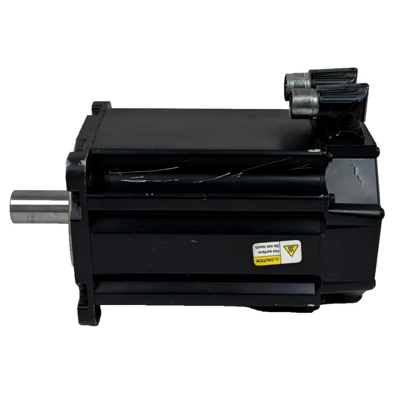
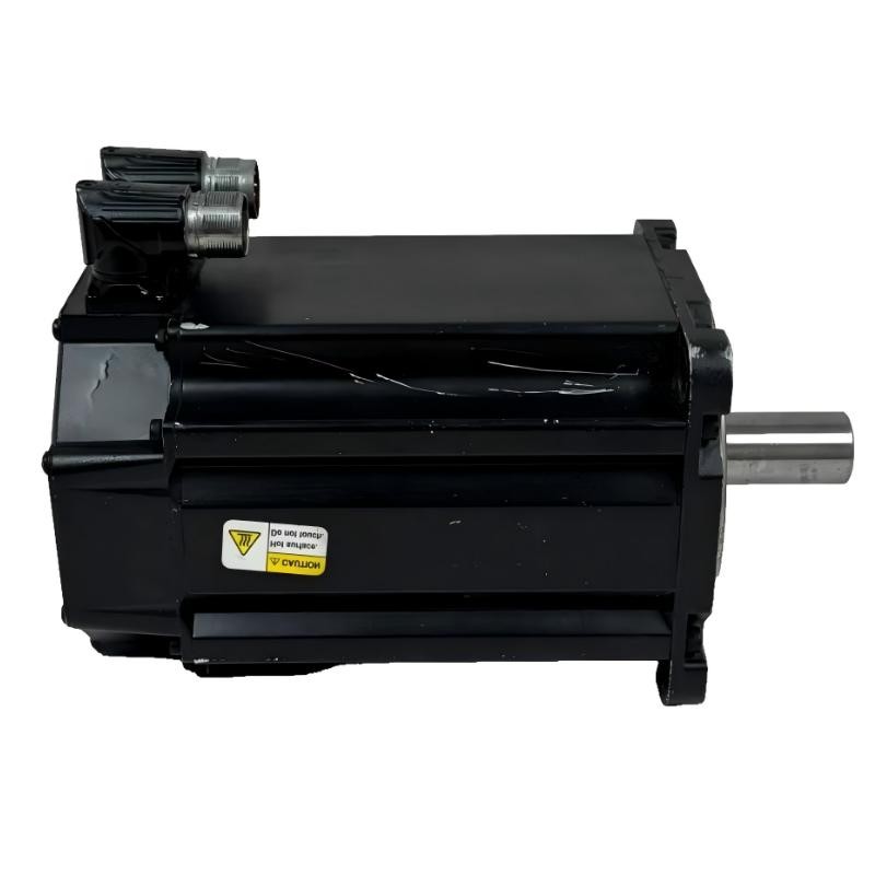
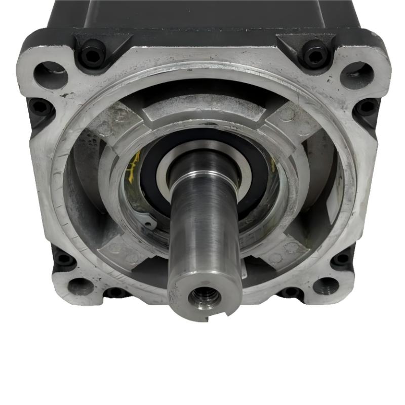
- Allen Bradley
- MPL-B960C-MJ72AA
- Low-Inertia Brushless Servo Motors Product
- USA
- 215 mm ×203.2 mm × 325 mm
- 42.7 kg
- Xiamen, China
- New & In Stock
- T/T, PayPal, Western Union
- 1 Year
- 1-3 Working Days
- DHL, UPS, TNT, FedEx and EMS.
- 24-Hour Service
- COO
- 12
Our advantage

Global Logistics
We have a 10-year logistics and express cooperation agreement, so our products can be shipped to any place in the world.

Brand new and original
Our products are imported in bulk from the place of origin. Because of the cooperative relationship, our products are all original and 100% new.

24-hour service
We provide 7*24 hours service to our customers. We will be there whenever you need us.

Price advantage
All our products are priced very favorably because we have our own warehouse and supply.
| Company Information | |||
| [email protected] | |||
| Mobile | +8615980777398 | ||
| +8615980777398 | |||
| 15980777398 |
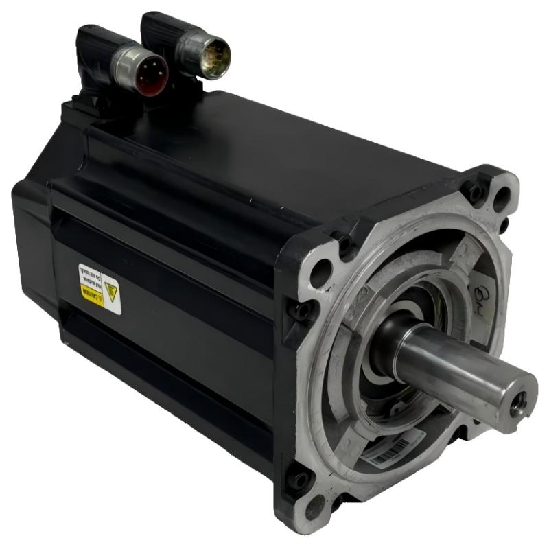
Allen-Bradley MPL-B960C-MJ72AA Servo Motor: Product Specifications, Technical Overview, Applications, Advantages, and Related Models
1. Product Overview
The Allen-Bradley MPL-B960C-MJ72AA is an industrial servo motor model within the MPL low-inertia brushless servo motor family. It is intended for automated machinery and motion-control systems that require controlled rotary movement, accurate positioning, repeatable motion, and coordinated acceleration and deceleration.
Servo motors are commonly used in industrial equipment where a motor must do more than rotate at a fixed speed. A servo drive and feedback system regulate the motor’s response to commands from a machine controller, allowing the equipment to perform positioning, speed regulation, and coordinated movement.
The MPL family is associated with industrial automation applications such as packaging machinery, automated assembly, material handling, indexing equipment, and precision positioning systems. The actual suitability of an individual motor depends on its electrical ratings, torque-speed characteristics, mechanical dimensions, feedback configuration, and compatibility with the selected drive.
The MPL-B960C-MJ72AA model designation is important when specifying a replacement or integrating a motor into an existing machine. Similar model numbers can identify different speed ratings, feedback arrangements, brake options, or mechanical configurations. These differences must be considered before purchasing or installing a substitute.
This report provides a detailed technical overview, a structured specification table, typical applications, practical advantages, and two groups of five related model recommendations. Exact measurements and ratings that cannot be established confidently are marked for verification rather than presented as confirmed engineering data.
2. Brand, Product Series, and Classification
|
Item |
Product details |
|---|---|
|
Brand |
Allen-Bradley |
|
Product series |
MPL |
|
Product family |
MP-Series low-inertia servo motors |
|
Complete model number |
MPL-B960C-MJ72AA |
|
Product category |
Industrial rotary servo motor |
|
Motor technology |
Brushless permanent-magnet servo motor |
|
Electrical voltage class |
460 V AC configuration |
|
Frame-size designation |
9 |
|
Frame dimension designation |
300 mm (11.81 in.) |
|
Magnet stack length |
152.4 mm (6.00 in.) |
|
Nominal speed classification |
1,500 RPM |
|
Feedback configuration |
High-resolution multi-turn encoder configuration, subject to exact catalog confirmation |
|
Shaft arrangement |
Keyed shaft extension |
|
Connector arrangement |
Right-angle SpeedTEC DIN configuration, subject to exact suffix confirmation |
|
Holding brake |
No brake indicated by the compared MJ72AA configuration; confirm exact catalog documentation |
|
Mounting arrangement |
Metric flange mounting; verify exact flange and bolt pattern |
|
Main function |
Closed-loop rotary motion control |
|
Typical equipment |
Industrial automated machinery and positioning systems |
|
Overall dimensions |
Require the exact dimensional drawing |
|
Net weight |
Not verified; kg value must be confirmed |
The model is part of the MPL family, which is designed for servo-controlled motion rather than simple fixed-speed operation. Its 1,500 RPM classification distinguishes the C configuration from related B and D configurations discussed below.
The voltage class and speed classification alone do not establish the motor’s continuous torque, peak torque, output power, or maximum permissible operating speed. Those values should be obtained from the exact catalog specification and evaluated alongside the drive and load requirements.
3. Detailed Technical Specifications
The following table summarizes the principal technical characteristics of the MPL-B960C-MJ72AA. The model is a 460 V-class, 1,500 RPM low-inertia servo motor with multi-turn absolute feedback, a keyed shaft, a rotatable right-angle connector, and no integral holding brake.
|
Parameter |
Specification |
|---|---|
|
Model number |
MPL-B960C-MJ72AA |
|
Brand |
Allen-Bradley |
|
Product series |
MPL |
|
Product family |
MP-Series low-inertia brushless servo motors |
|
Motor type |
AC rotary servo motor |
|
Motor construction |
Brushless permanent-magnet motor |
|
Armature voltage |
460 V AC |
|
Drive system |
Compatible industrial servo drive |
|
Frame size |
9 |
|
Frame dimension designation |
300 mm (11.81 in.) |
|
Magnet stack length |
152.4 mm (6.00 in.) |
|
Nominal speed classification |
1,500 RPM |
|
Feedback |
Multi-turn, high-resolution absolute encoder |
|
Shaft type |
Keyed shaft extension |
|
Connector type |
SpeedTEC DIN connector |
|
Connector orientation |
Right-angle |
|
Connector rotation |
180° rotatable |
|
Holding brake |
No integral brake |
|
Mounting |
IEC metric flange, free mounting holes, Type FF |
|
Continuous stall torque |
Approximately 76 N·m, subject to rating-condition verification |
|
Peak torque |
Approximately 124 N·m, subject to rating-condition verification |
|
Rated continuous current |
Verify against the applicable motor data |
|
Peak current |
Verify against the applicable motor data |
|
Rated output power |
Verify against the applicable motor data |
|
Maximum operating speed |
Confirm the permitted operating envelope |
|
Overall length |
Exact dimensional drawing required |
|
Overall width |
Exact dimensional drawing required |
|
Overall height |
Exact dimensional drawing required |
|
Shaft diameter |
Exact dimensional drawing required |
|
Shaft extension length |
Exact dimensional drawing required |
|
Net weight |
Exact catalog-specific weight not established |
|
Weight in kilograms (kg) |
Must be confirmed before engineering or procurement use |
|
Protection rating |
Verify the exact configuration |
|
Operating temperature |
Verify the applicable operating limits |
|
Typical control mode |
Position, speed, or torque control through a compatible drive |
3.1 Physical Dimensions and Weight
The physical dimensions of a servo motor are essential when replacing an existing unit or designing a new machine. The frame designation and magnet stack length provide useful identification information, but they do not define every external dimension.
|
Physical parameter |
Value |
Engineering significance |
|---|---|---|
|
Frame-size designation |
300 mm (11.81 in.) |
Identifies the frame-size class |
|
Magnet stack length |
152.4 mm (6.00 in.) |
Identifies the active motor stack configuration |
|
Overall motor length |
Not verified |
Determines axial installation clearance |
|
Motor body width |
Not verified |
Determines lateral clearance |
|
Motor body height |
Not verified |
Determines vertical clearance |
|
Mounting flange dimensions |
Verify drawing |
Determines bolt-hole and alignment compatibility |
|
Shaft diameter |
Not verified |
Determines coupling compatibility |
|
Shaft extension length |
Not verified |
Determines available coupling engagement |
|
Connector clearance |
Verify installation drawing |
Prevents interference with adjacent equipment |
|
Net motor weight |
Not verified |
Required for support and lifting calculations |
|
Net weight in kg |
Not confirmed |
Must be obtained from exact model data |
|
Packaged shipping weight |
Not verified |
May include protective packaging and accessories |
For a reliable installation, the complete dimensional drawing should be used to establish the motor’s external envelope. The connector and cable routing also need to be included in the available space.
Weight information: An exact net weight in kilograms has not been established here for the complete MPL-B960C-MJ72AA configuration. It is better to leave this field unconfirmed than to use an assumed figure for machine design, transport calculations, or load-bearing structures.
3.2 Electrical and Performance Parameters
|
Parameter |
Description |
Selection consideration |
|---|---|---|
|
Supply voltage class |
460 V AC motor configuration |
Match the drive and motor electrical requirements |
|
Motor speed |
1,500 RPM nominal classification |
Evaluate the required operating speed and load |
|
Torque output |
Governed by the motor’s torque-speed characteristics |
Confirm continuous and peak requirements |
|
Continuous operation |
Depends on the permitted thermal operating conditions |
Consider duty cycle and ambient temperature |
|
Peak operation |
Limited by motor and drive ratings |
Check acceleration and transient loads |
|
Feedback resolution |
High-resolution encoder configuration |
Relevant to position feedback and control |
|
Multi-turn feedback |
Tracks position across multiple shaft revolutions |
Confirm absolute-position handling by the drive and controller |
|
Acceleration |
Depends on motor and load inertia |
Evaluate the complete mechanical system |
|
Deceleration |
Depends on the load, drive, and braking strategy |
Check stopping distance and regenerative requirements |
|
Thermal management |
Depends on current, duty cycle, and installation |
Avoid operation outside permitted thermal limits |
|
Mechanical loading |
Depends on shaft and bearing limits |
Verify radial and axial forces |
|
Brake arrangement |
No integral holding brake |
Evaluate external holding requirements where applicable |
The 1,500 RPM classification should not be treated as a guarantee that the motor can maintain that speed under every load condition. Likewise, the nominal torque and peak torque are not interchangeable: continuous torque is relevant to sustained operation, while peak torque generally applies to limited operating conditions.
4. Product Introduction and Operating Principle
The MPL-B960C-MJ72AA is designed to convert electrical power into controlled rotary motion. It operates as part of a motion-control system consisting of a servo motor, compatible drive, feedback interface, machine controller, and mechanical load.
When the controller commands a particular movement, the servo drive regulates the electrical current supplied to the motor. The motor generates torque, while the encoder provides position feedback. The control system compares the requested movement with the feedback information and adjusts the motor’s response.
This closed-loop arrangement allows the machine to regulate its position and speed rather than relying only on a fixed electrical supply frequency.
4.1 Brushless Permanent-Magnet Construction
The motor uses a brushless permanent-magnet design. Unlike a conventional brushed DC motor, it does not rely on brushes making electrical contact with a rotating commutator.
This construction is well suited to industrial servo applications because the motor can be controlled through an appropriate electronic drive. Eliminating brushes also removes the need for routine brush replacement, although bearings, connectors, cables, and other components still require maintenance.
4.2 Low-Inertia Design
The MPL family is intended for applications requiring responsive movement and controlled changes in speed.
Lower rotor inertia can help the motor accelerate and decelerate efficiently, especially in machinery with frequent positioning cycles. However, the inertia of the attached load can be much greater than the motor’s own inertia. Gearboxes, belts, pulleys, couplings, and driven mechanisms must therefore be included in the motion calculations.
4.3 Multi-Turn Absolute Feedback
The model’s multi-turn, high-resolution feedback arrangement provides position information across multiple shaft revolutions.
This is useful when a machine needs to determine shaft position without treating every position as a simple angle within a single revolution. The precise behavior after a power interruption depends on the encoder implementation, drive, and controller configuration.
When replacing a motor, the feedback type must be checked carefully. A motor with a single-turn encoder is not automatically interchangeable with one using multi-turn feedback.
4.4 Keyed Shaft Connection
The keyed shaft extension provides a mechanical interface for connecting the motor to a suitable coupling, pulley, gearbox, or other driven component.
The shaft diameter, key dimensions, extension length, alignment, and permissible shaft forces must be verified. An incorrect coupling can introduce vibration, increase bearing loads, and reduce the reliability of the motion system.
4.5 Rotatable Right-Angle Connector
The right-angle connector can be rotated through 180°, providing flexibility when arranging the motor’s electrical connections.
This is particularly helpful in compact machine assemblies where a straight connector could interfere with nearby components. Correct cable routing remains important: excessive bending, twisting, or pulling can damage the connector or cable over time.
4.6 No Integral Holding Brake
The specified configuration does not include an integral holding brake.
This may be suitable for horizontal rotary applications where a mechanical brake is not required. However, a vertical axis, suspended load, or mechanism that must remain stationary when power is removed needs a separate assessment of its holding and safety requirements.
A servo drive’s ability to control deceleration should not be confused with a mechanical holding function after power has been lost.
5. Main Product Applications

5.1 Packaging and Filling Machinery
Packaging equipment frequently requires accurate product indexing, controlled film feeding, synchronized cutting, and repeatable movement between production stages.
A servo motor can support these operations by regulating position and speed through a compatible drive. The 1,500 RPM classification of the MPL-B960C configuration makes it a candidate for systems whose required speed and torque fall within its operating envelope.
Final selection depends on the machine’s cycle time, load inertia, acceleration profile, and required positioning accuracy.

5.2 Automated Assembly Equipment
Automated assembly machines use servo-controlled movement to position fixtures, rotate components, transfer workpieces, and coordinate individual assembly operations.
Feedback-based control can help improve movement repeatability and synchronization between machine stations. Correct mechanical alignment and controller tuning are essential to achieving the desired production consistency.

5.3 Machine Tools and Rotary Positioning
Rotary tables, indexing units, auxiliary feed mechanisms, and positioning assemblies can use servo motors to control the movement of machine components.
The multi-turn feedback arrangement may be useful where the application needs position information across multiple rotations. The actual level of positioning accuracy depends on the entire system, including feedback, mechanical backlash, structural stiffness, and control tuning.

5.4 Material Handling and Transfer Systems
Servo-controlled transfer units can regulate the movement of components between workstations, while automated sorting and indexing systems can use programmed positioning to coordinate the handling process.
Motor selection should consider the mass being moved, the transmission ratio, acceleration, stopping requirements, and the mechanical loads applied to the shaft.

5.5 Printing, Labeling, and Converting Equipment
Printing and converting systems may use servo motors for roller positioning, controlled feeding, registration, cutting, and coordinated movement of materials.
A properly configured servo system can help maintain consistent movement between operations. The motor must be selected according to the required speed range, load characteristics, and control-system compatibility.
5.6 Additional Applications
Other potential applications include automated inspection equipment, rotary indexing stations, specialized manufacturing machinery, laboratory automation equipment, and industrial test systems.
The model should not be selected solely because its general product family is associated with these applications. The required torque, speed, feedback behavior, environmental protection, mechanical loading, and drive compatibility must all be checked against the actual installation.
6. Product Advantages
|
Advantage |
Practical benefit |
Important consideration |
|---|---|---|
|
Brushless construction |
Eliminates routine brush replacement |
Bearings and other components still need inspection |
|
Low-inertia motor family |
Can support responsive acceleration and deceleration |
Total load inertia must be calculated |
|
Multi-turn feedback |
Provides position information across multiple rotations |
Confirm encoder and controller compatibility |
|
High-resolution feedback |
Supports detailed motion-control feedback |
System accuracy also depends on mechanics and tuning |
|
1,500 RPM classification |
Provides a defined speed class for motor selection |
Torque at the operating speed must be checked |
|
Keyed shaft |
Provides a conventional mechanical coupling interface |
Shaft and key dimensions must match |
|
Rotatable right-angle connector |
Allows flexible cable routing |
Maintain adequate clearance and cable bend radius |
|
Metric flange mounting |
Can simplify integration into compatible machinery |
Confirm flange and bolt-hole dimensions |
|
No integral brake |
Avoids an unnecessary brake where one is not required |
Separate holding provisions may be necessary |
|
Related motor variants |
Provides alternative speed, stack-length, and brake configurations within the wider family |
Similar catalog numbers are not necessarily direct replacements |
6.1 Controlled and Repeatable Motion
A properly sized and tuned servo system can execute repeated movements with consistent timing and position feedback.
This is valuable for automated machinery that must perform the same movement many times during a production shift. Consistency depends on the motor, drive, controller, mechanical transmission, and operating conditions working together.
6.2 Flexible Motion Programming
A servo drive can be configured to execute different movement profiles, including controlled acceleration, deceleration, and positioning sequences.
This flexibility is useful when a machine has several operating modes or requires coordination between multiple axes. The precise available functions depend on the controller and drive system used with the motor.
6.3 Reduced Brush Maintenance
The brushless construction removes the routine maintenance associated with replacing motor brushes.
It does not eliminate the need for preventive maintenance. Bearing condition, vibration, connector integrity, cable insulation, temperature, shaft alignment, and contamination should still be monitored.
6.4 Installation Flexibility
The metric mounting arrangement and rotatable connector can help with integration into existing machine layouts.
However, physical compatibility must be verified using the exact dimensional drawing. A motor that shares the same frame-size designation may still differ in shaft geometry, total length, connector clearance, or other important mechanical features.
6.5 Integration with a Compatible Servo System
The MPL motor family is intended for industrial motion-control applications. When the motor, drive, feedback interface, and controller are compatible, they can form an integrated system for regulating machine movement.
The exact drive model, feedback support, wiring, parameter configuration, and commissioning procedure must be established for the particular installation.
7. Five Recommended Models from the Same MPL Series
The following models are related MPL configurations worth comparing with the MPL-B960C-MJ72AA. They cover different speed classifications, feedback arrangements, frame configurations, and magnet stack lengths.
The specifications below identify the key catalog differences. Dimensions and net weights are not filled with guessed values where exact figures have not been established.
|
Model |
Voltage class |
Frame designation |
Stack length |
Speed classification |
Feedback |
Brake |
Overall dimensions |
Weight (kg) |
|---|---|---|---|---|---|---|---|---|
|
MPL-B960B-MJ72AA |
460 V |
9 / 300 mm |
152.4 mm |
1,000 RPM |
Multi-turn, high-resolution |
No |
Drawing required |
Not verified |
|
MPL-B960D-MJ72AA |
460 V |
9 / 300 mm |
152.4 mm |
2,000 RPM |
Multi-turn, high-resolution |
No |
Drawing required |
Not verified |
|
MPL-B960D-MJ74AA |
460 V |
9 / 300 mm |
152.4 mm |
2,000 RPM |
Multi-turn, high-resolution |
Brake-equipped configuration; verify exact catalog data |
Drawing required |
Not verified |
|
MPL-B980B-MJ72AA |
460 V |
9 / 300 mm |
203.2 mm |
1,000 RPM |
Multi-turn, high-resolution |
No |
Drawing required |
Not verified |
|
MPL-B980C-MJ72AA |
460 V |
9 / 300 mm |
203.2 mm |
1,500 RPM |
Multi-turn, high-resolution |
No |
Drawing required |
Not verified |
Frame designations, stack lengths, speed classifications, and the exact brake configuration should be confirmed against the full catalog number before purchase. Complete dimensions and net weight in kg require the corresponding mechanical data.
7.1 MPL-B960B-MJ72AA
This is a related B960 configuration with a 1,000 RPM nominal speed classification and multi-turn feedback.
It is worth considering where the application requires a lower nominal speed than the 1,500 RPM reference model. The actual suitability depends on the torque required at the operating point, the load inertia, and the machine’s cycle time.
Typical selection reason: The application needs the same general frame and stack-length class but has different speed requirements.
7.2 MPL-B960D-MJ72AA
The B960D configuration is associated with a 2,000 RPM speed classification while retaining the general B960 frame and stack-length designation.
It can be evaluated for machinery requiring a higher nominal speed range. Higher speed alone does not establish higher available torque, so the applicable torque-speed curve and drive limits must be checked.
Typical selection reason: The machine requires a different nominal speed while retaining a related motor configuration.
7.3 MPL-B960D-MJ74AA
This model is a related B960D catalog configuration associated with a brake-equipped option. The complete suffix should be verified to establish the exact brake arrangement and electrical requirements.
A holding brake may be relevant to an axis that needs to remain stationary when the motor is de-energized. It should not be assumed suitable for every stopping or emergency-braking function.
Typical selection reason: The application requires a compatible holding-brake function and a higher nominal speed classification.
7.4 MPL-B980B-MJ72AA
The B980B configuration has a longer 203.2 mm magnet stack, compared with the 152.4 mm stack of the B960C.
This makes it a different physical configuration and a candidate for applications requiring a different motor performance profile. The overall installation envelope and mounting arrangement should be reviewed before considering it as a replacement.
Typical selection reason: The application needs a longer-stack motor configuration with a 1,000 RPM nominal speed classification.
7.5 MPL-B980C-MJ72AA
The B980C is a related MPL configuration with a 203.2 mm stack designation and a 1,500 RPM speed classification.
It may be worth evaluating when the reference model’s general speed classification is appropriate but a different motor stack configuration is needed.
Typical selection reason: The application requires a 1,500 RPM configuration with a longer magnet stack.
8. Five Additional Allen-Bradley Models to Consider
These additional models broaden the comparison to other servo motor configurations and product families. They are candidates for evaluation rather than a verified ranking of current sales popularity.
|
Model |
Product family |
Voltage class |
Frame designation |
Stack length |
Speed classification |
Feedback / configuration |
Dimensions |
Weight (kg) |
|---|---|---|---|---|---|---|---|---|
|
MPL-B880C-SJ72AA |
MPL |
460 V |
8 / 265 mm |
203.2 mm |
1,500 RPM |
Single-turn, high-resolution |
Drawing required |
Not verified |
|
MPL-B880D-SJ72AA |
MPL |
460 V |
8 / 265 mm |
203.2 mm |
2,000 RPM |
Single-turn, high-resolution |
Drawing required |
Not verified |
|
MPL-B960B-SJ72AA |
MPL |
460 V |
9 / 300 mm |
152.4 mm |
1,000 RPM |
Single-turn, high-resolution |
Drawing required |
Not verified |
|
MPL-B980D-MJ72AA |
MPL |
460 V |
9 / 300 mm |
203.2 mm |
2,000 RPM |
Multi-turn, high-resolution |
Drawing required |
Not verified |
|
MPF-B540K-SJ72AA |
MPF |
Confirm exact configuration |
Confirm exact configuration |
Confirm exact configuration |
Confirm exact configuration |
Confirm exact feedback configuration |
Drawing required |
Not verified |
The MPL models are related configurations for technical comparison. The MPF model is included as a broader product-family candidate; verify its exact catalog identity and all ratings before considering it for a particular machine.
8.1 MPL-B880C-SJ72AA
This model belongs to the MPL family and has a frame-size-8 designation, a 203.2 mm stack length, and a 1,500 RPM nominal speed classification.
Its different frame size means that it should not be assumed to fit the same mounting arrangement as the B960C. It is worth considering when a machine’s mechanical design and required motor characteristics favor this configuration.
8.2 MPL-B880D-SJ72AA
The B880D configuration shares the general frame and stack designation of the B880C while having a 2,000 RPM nominal speed classification.
It may be evaluated for a suitable higher-speed application, provided the drive, load, shaft loading, and mounting dimensions are compatible.
8.3 MPL-B960B-SJ72AA
The B960B-SJ72AA is a closely related alternative with a 1,000 RPM speed classification and single-turn feedback.
It is useful for comparison where the machine has different speed requirements or does not need the same multi-turn feedback arrangement as the reference model.
The encoder type and the control system’s position-reference strategy should be checked before a replacement is selected.
8.4 MPL-B980D-MJ72AA
The B980D configuration combines a longer 203.2 mm stack designation with a 2,000 RPM nominal speed classification and multi-turn feedback.
It may be evaluated for applications that need the relevant speed range and feedback characteristics. Its longer stack means the total motor envelope must be checked carefully.
8.5 MPF-B540K-SJ72AA
This model is included as a broader family comparison rather than a confirmed drop-in replacement.
Before considering it, establish the exact catalog configuration, rated voltage, speed, torque, feedback, brake, shaft geometry, connector arrangement, overall dimensions, and weight.
For a machine retrofit, it is generally more straightforward to begin by comparing models within the same MPL configuration family before moving to another family.
9. Model Comparison and Selection Guide
|
Requirement |
Model worth evaluating |
Main reason |
Critical check |
|---|---|---|---|
|
Lower nominal speed |
MPL-B960B-MJ72AA |
Related B960 frame and stack configuration |
Continuous torque and feedback compatibility |
|
Higher nominal speed |
MPL-B960D-MJ72AA |
2,000 RPM classification |
Torque-speed curve and permitted speed |
|
Brake-equipped option |
MPL-B960D-MJ74AA |
Related brake-equipped configuration |
Exact brake ratings and control requirements |
|
Longer motor stack |
MPL-B980B-MJ72AA |
203.2 mm stack designation |
Overall length and installation clearance |
|
Longer stack at 1,500 RPM |
MPL-B980C-MJ72AA |
Similar nominal speed with a different stack length |
Mechanical envelope and drive compatibility |
|
Different frame size |
MPL-B880C-SJ72AA |
Frame-size-8 configuration |
Flange, shaft, and mounting dimensions |
|
Higher speed with a different frame size |
MPL-B880D-SJ72AA |
Frame-size-8, 2,000 RPM configuration |
Load inertia and shaft loading |
|
Single-turn feedback |
MPL-B960B-SJ72AA |
Single-turn feedback configuration |
Position-reference requirements |
|
Longer stack and higher speed |
MPL-B980D-MJ72AA |
203.2 mm stack and 2,000 RPM classification |
Torque, speed, and clearance |
10. Installation and Maintenance Considerations
10.1 Servo Drive Compatibility
The motor must be paired with a drive that supports its electrical ratings and feedback arrangement. Verify the required voltage, current, feedback interface, motor identification parameters, and permitted operating range.
A motor may share the same product family as an existing unit without being compatible with the same drive settings.
10.2 Mechanical Installation
Check the flange, bolt pattern, shaft diameter, key dimensions, coupling alignment, and available clearance. Avoid transferring excessive radial or axial force to the motor shaft.
Misalignment can increase vibration and bearing wear. A flexible coupling may accommodate limited alignment differences, but it must still be selected and installed within its permitted operating limits.
10.3 Cable Routing
The right-angle connector provides some flexibility for cable orientation. During installation, ensure that the connector and cable do not contact nearby moving components or machine structures.
Avoid excessive bending, twisting, pulling, or strain at the connector. Follow the specified cable-routing and grounding requirements for the drive system.
10.4 Thermal Management
The motor’s temperature depends on load, current, duty cycle, ambient conditions, and installation. Continuous operation near the limits of the motor’s rated performance may require particular attention to thermal conditions.
Use the applicable motor and drive specifications when calculating continuous and peak duty.
10.5 Preventive Maintenance
A practical maintenance program can include:
-
Inspecting cables and connectors for wear or damage.
-
Checking mounting bolts and mechanical alignment.
-
Monitoring vibration and abnormal noise.
-
Inspecting shaft couplings and driven mechanisms.
-
Reviewing motor temperature during representative operation.
-
Checking for contamination and moisture exposure.
-
Reviewing drive alarms and feedback faults.
-
Confirming that the motor is operating within its rated limits.
The appropriate inspection interval depends on the machine’s operating hours, environment, load, and maintenance requirements.
11. Final Product Summary
The Allen-Bradley MPL-B960C-MJ72AA is a 460 V-class, 1,500 RPM low-inertia brushless rotary servo motor in the MPL series. Its principal catalog characteristics include a 300 mm frame-size designation, a 152.4 mm magnet stack length, multi-turn high-resolution absolute feedback, a keyed shaft extension, a rotatable right-angle connector, metric flange mounting, and no integral holding brake.
Its intended role is controlled rotary motion in industrial machinery. Potential applications include packaging, automated assembly, material handling, indexing, and precision positioning, provided that the motor’s ratings match the machine’s requirements.
The most relevant related configurations include the MPL-B960B, MPL-B960D, MPL-B980B, and MPL-B980C models. The best choice depends on the required speed, torque, feedback arrangement, brake function, and available installation space.
For procurement and engineering use, the final specification should include the exact overall dimensions and verified net weight in kilograms. Those values must be established from the applicable dimensional data rather than inferred from the frame-size designation or magnet stack length.