

ProductPRODUCT
Featured products
Contact Us
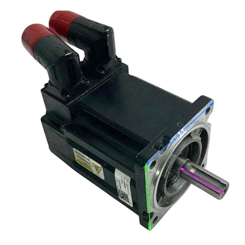
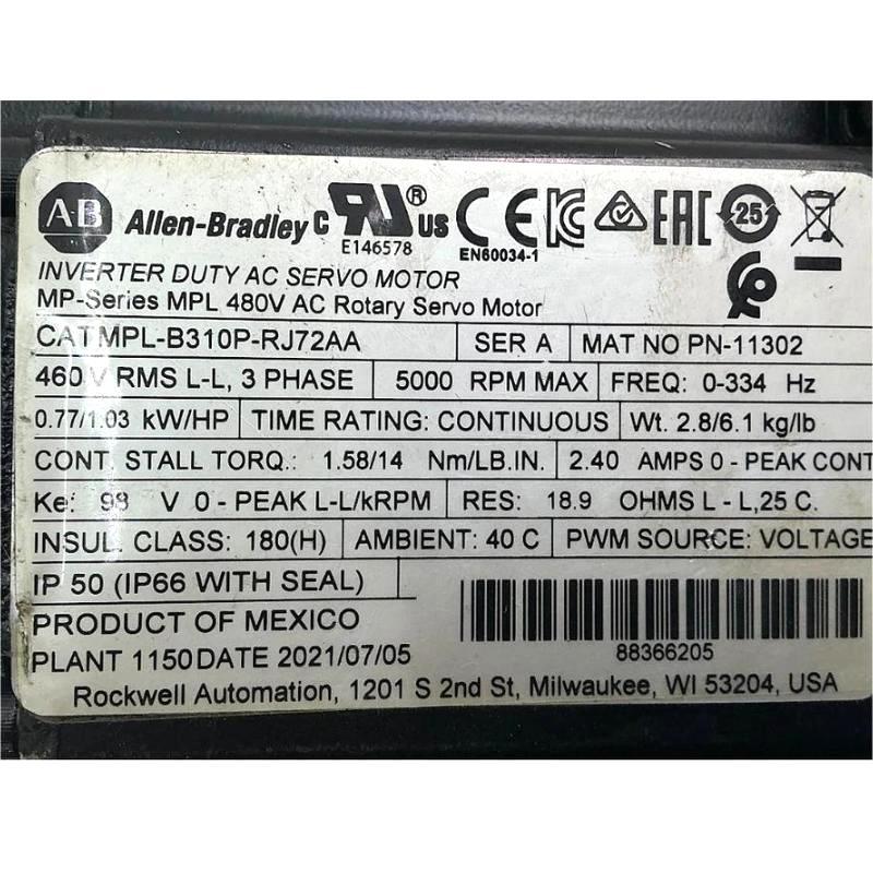
- Allen Bradley
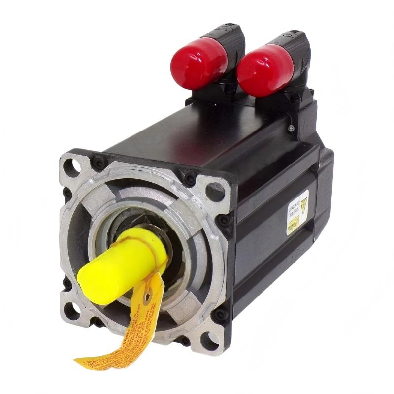
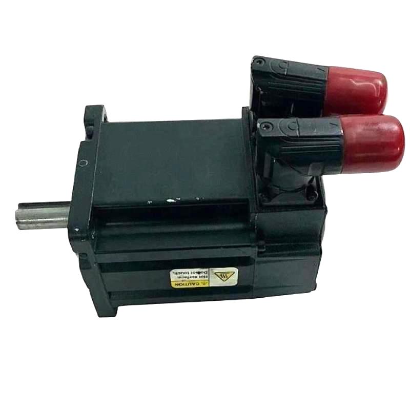
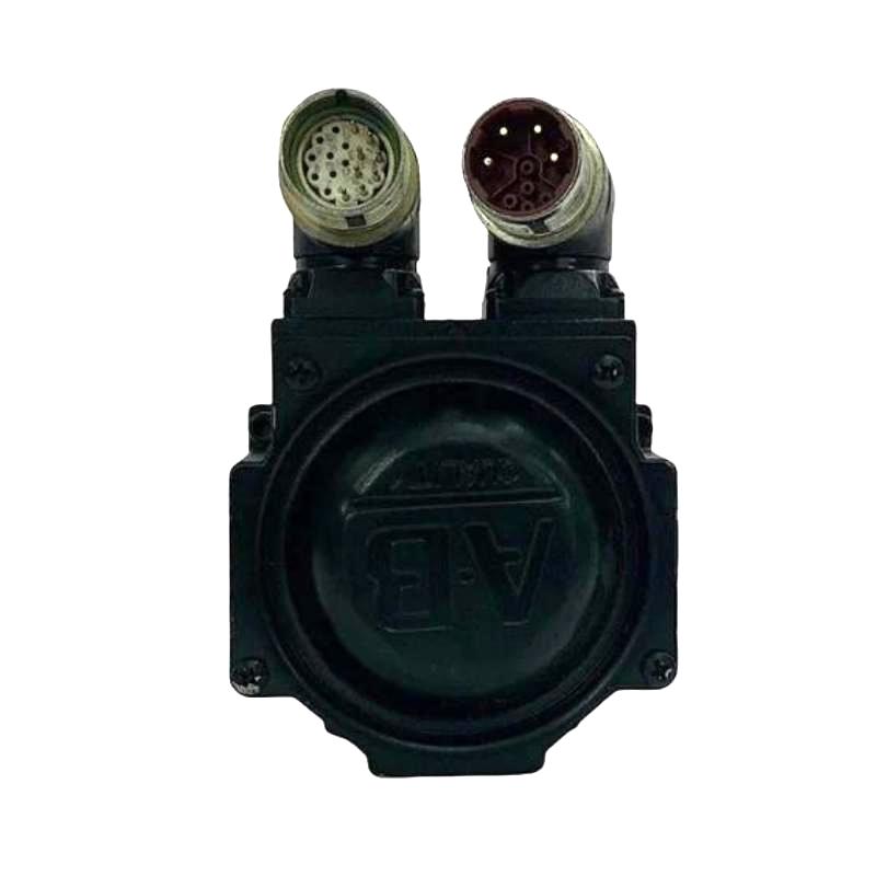
- MPL-B310P-RJ72AA
- Servo Motor
- USA
- 100 mm
- 2.7 kg
- Xiamen, China
- New & In Stock
- T/T, PayPal, Western Union
- 1 Year
- 1-3 Working Days
- DHL, UPS, TNT, FedEx and EMS.
- 24-Hour Service
- COO
- 3
Our advantage

Global Logistics
We have a 10-year logistics and express cooperation agreement, so our products can be shipped to any place in the world.

Brand new and original
Our products are imported in bulk from the place of origin. Because of the cooperative relationship, our products are all original and 100% new.

24-hour service
We provide 7*24 hours service to our customers. We will be there whenever you need us.

Price advantage
All our products are priced very favorably because we have our own warehouse and supply.
| Company Information | |||
| [email protected] | |||
| Mobile | +8615980777398 | ||
| +8615980777398 | |||
| 15980777398 |
Product Overview
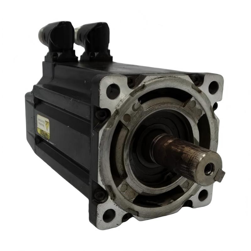
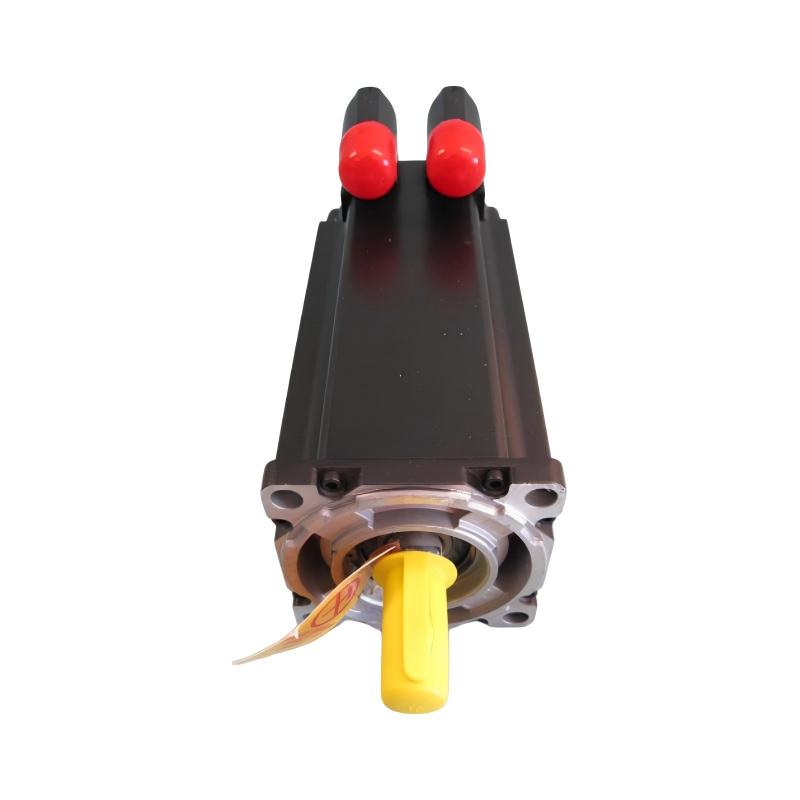
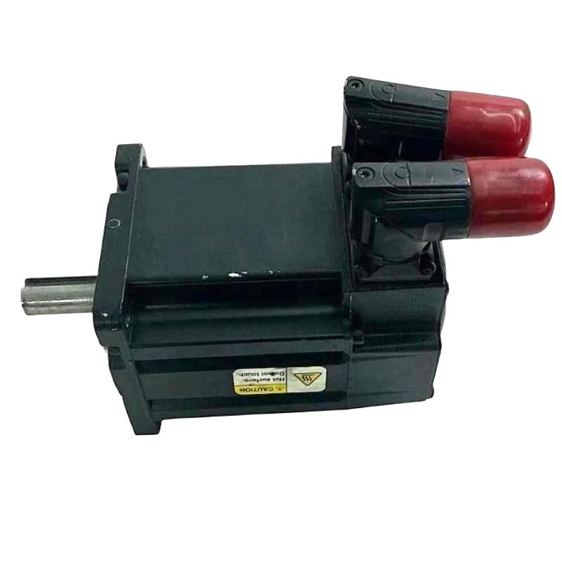
The Allen Bradley MPL-B310P-RJ72AA Servo Motor is an industrial motion-control component designed for applications that require controlled rotational movement, repeatable positioning, and coordinated machine operation. As identified in the supplied product description, this motor belongs to the Allen-Bradley MPL servo motor family and is intended for integration into compatible industrial servo systems.
Servo motors are widely used in automated manufacturing because they work with a suitable servo drive and feedback arrangement to control motor position, speed, and torque. Unlike a conventional motor operating at a fixed or manually adjusted speed, a servo motor can participate in a closed-loop motion-control system in which the controller compares commanded movement with feedback and adjusts motor operation accordingly.
The MPL-B310P-RJ72AA has a supplied frame size of 100 mm and a listed weight of 2.7 kg. These physical characteristics are useful when evaluating mechanical installation space, motor mounting arrangements, and replacement logistics. Actual mounting dimensions, shaft geometry, connector orientation, and mechanical interface details should be checked against the exact motor documentation before installation.
When correctly matched with a compatible servo drive, feedback system, controller, and machine mechanics, a servo motor can support accurate movement and consistent performance in demanding automation applications. The precise electrical ratings, feedback configuration, brake options, and connector specifications for this particular catalog number should be verified before procurement or commissioning.
Technical Specifications
| Parameter | Specification |
|---|---|
| Manufacturer | Allen-Bradley |
| Product Brand | Allen-Bradley / Rockwell Automation |
| Model | MPL-B310P-RJ72AA |
| Product Type | Servo Motor |
| Product Family | MPL Servo Motor Series |
| Frame Size | 100 mm |
| Weight | 2.7 kg |
| Primary Function | Controlled rotational motion |
| Typical Control Arrangement | Servo drive with a compatible motion controller and feedback system |
| Motion Variables | Position, speed, and torque, depending on the complete servo system |
| Installation | Machine-mounted; verify the specified mounting arrangement |
| Typical Applications | Automated machinery, positioning systems, packaging, and material handling |
| Electrical Ratings | Confirm from the exact motor nameplate and technical documentation |
| Feedback Type | Verify the exact encoder or feedback configuration |
| Brake Configuration | Confirm whether the specified variant includes a holding brake |
| Shaft and Mounting Details | Verify against the exact model drawing |
The specifications above preserve the model number, frame size, and weight supplied for this product. Parameters such as rated voltage, continuous stall torque, rated speed, peak torque, feedback resolution, shaft dimensions, and connector type should not be assumed from the model designation alone.
What Is the Allen Bradley MPL-B310P-RJ72AA Servo Motor?
A servo motor is designed to operate as part of a controlled motion system. Its purpose is not simply to rotate a shaft, but to produce movement that follows commands from a compatible drive and controller.
In a typical industrial application, the controller generates a motion command based on the machine sequence or production requirements. The servo drive processes the command and supplies controlled electrical power to the motor. A feedback device, when incorporated into the system, provides information about actual motor movement so the control system can regulate operation.
The MPL-B310P-RJ72AA is identified as a servo motor within the MPL product family. Its suitability for a particular machine depends on the complete motor specification and compatibility with the associated servo drive, feedback interface, and mechanical load.
A simplified servo-control arrangement is:
Motion Controller → Servo Drive → Servo Motor → Mechanical Load
Where supported by the selected hardware, feedback is returned from the motor to the drive or control system to support closed-loop regulation.
This coordinated operation is particularly useful when a machine must move to defined positions, maintain controlled speed, synchronize multiple axes, or repeat the same movement cycle with consistency.
Function and Working Principle
1. Conversion of Electrical Energy into Mechanical Motion
The servo drive supplies controlled electrical power to the motor according to the requested motion and the motor’s electrical characteristics. The motor converts this energy into rotational motion at its shaft.
The actual output depends on the motor design, drive configuration, supply conditions, and mechanical load. Correct motor-drive matching is essential for stable operation.
2. Controlled Speed and Torque
The drive regulates motor operation according to the motion command and system limits. Speed control determines how quickly the shaft rotates, while torque control governs the rotational force produced within the limits of the motor and drive.
These capabilities allow a machine to accelerate, decelerate, and move loads in a controlled manner. The allowable speed and torque range must be determined from the motor’s actual ratings and the application requirements.
3. Position Control
In a position-controlled application, the controller specifies a target position or movement distance. The servo system uses its supported feedback and control functions to move the motor toward the commanded position.
Position control is important for equipment such as indexing tables, automated assembly stations, cutting systems, and packaging machinery where the location of a mechanical component affects product quality or production timing.
4. Feedback and Motion Correction
A compatible feedback device can report information about motor position or movement. The servo system compares this feedback with the command and adjusts motor operation to reduce the difference between the desired and actual motion.
The exact feedback device and signal interface depend on the motor variant and associated drive. The feedback arrangement should be confirmed before a replacement motor is connected.
5. Coordinated Machine Operation
In multi-axis equipment, servo motors may be coordinated so that several mechanical movements occur in a defined relationship. This can support synchronized conveyors, electronic gearing, coordinated handling systems, and complex machine sequences when the controller and drives provide the required functions.
The MPL-B310P-RJ72AA should therefore be selected as part of a complete motion-control solution rather than as an isolated component.
Role in Industrial Automation Systems
Within an automated machine, the servo motor acts as the electromechanical element that produces commanded movement. The controller determines what movement is required, the servo drive regulates electrical power, and the motor produces the mechanical output.
A typical system can include:
| System Component | Function |
|---|---|
| PLC or Motion Controller | Executes machine logic and generates motion commands |
| Servo Drive | Controls the electrical power supplied to the motor |
| MPL-B310P-RJ72AA Servo Motor | Converts controlled electrical energy into rotational motion |
| Feedback Device | Provides supported motion or position information |
| Mechanical Transmission | Transfers motor torque to the driven mechanism |
| Coupling or Gearbox | Connects the motor to the machine where required |
| Operator Interface | Allows operators to issue commands and monitor machine status |
| Industrial Network | Exchanges control and diagnostic data when supported by the selected system |
The exact architecture depends on the machine design and the drive and controller selected. The motor model, feedback interface, drive firmware, and control-system configuration should be checked together.
Industrial Applications
Packaging Machinery
Packaging equipment often requires repeatable positioning and coordinated motion for product feeding, indexing, filling, sealing, labeling, and cutting. A compatible servo system can control the movement of rollers, positioning mechanisms, and other machine axes.
The suitability of the MPL-B310P-RJ72AA depends on the torque, speed, duty cycle, and mechanical requirements of the specific packaging machine.
Automated Assembly Equipment
Assembly machines may require controlled movement to place, position, or transfer components. Servo motors can provide the motion needed for repetitive operations where movement timing and positioning influence assembly consistency.
Material Handling Systems
Servo-driven mechanisms can support controlled movement in transfer units, pick-and-place equipment, and positioning stages. Applications should be evaluated according to load inertia, acceleration requirements, mechanical transmission, and the required positioning performance.
Indexing and Positioning Systems
Indexing tables and rotary positioning mechanisms use controlled movement to bring workpieces or tooling to defined locations. A servo motor operating with a suitable drive and controller can help achieve repeatable indexing cycles.
Printing and Converting Equipment
Printing, cutting, and converting machines may use servo systems to coordinate web movement, rollers, and cutting mechanisms. Proper motor sizing and system tuning are important when speed changes and synchronization affect the final product.
General Manufacturing Automation
Servo motors can also be incorporated into automated production equipment that requires controlled movement, repeatable cycles, or coordinated axes. The motor must be selected according to the actual mechanical load and operating profile rather than frame size alone.
Installation and Mechanical Integration
Correct installation helps prevent excessive vibration, shaft loading, alignment problems, and premature component wear.
Verify Motor Identification
Before installation, confirm the complete motor model MPL-B310P-RJ72AA from the nameplate and compare it with the machine’s original bill of materials or maintenance records.
Check the nameplate, revision or catalog markings where applicable, connector arrangement, and mechanical interface. A motor with a similar frame size may still have different electrical or mechanical characteristics.
Confirm Mounting Dimensions
The supplied frame size is 100 mm. However, frame size alone does not establish the complete mounting geometry.
Before fitting the motor, verify:
- Mounting-hole positions and dimensions
- Shaft diameter and extension
- Shaft-key or coupling requirements, if applicable
- Motor length and clearance
- Connector location and cable bend radius
- Permitted mounting orientation
- Required access for servicing
Use the exact mechanical drawing for final installation planning.
Check the Mechanical Load
Confirm that the motor can meet the application’s torque, speed, acceleration, deceleration, and duty-cycle requirements. Consider the inertia of the load and any gearbox, coupling, belt, screw, or other transmission mechanism.
An undersized motor may fail to meet the required motion profile, while an incorrectly configured or oversized system may create tuning and operating difficulties.
Align the Shaft and Coupling
Misalignment between the motor shaft and driven mechanism can increase bearing loads, vibration, and mechanical wear. Align couplings and transmission components according to the equipment specifications.
Avoid applying excessive axial or radial force to the motor shaft. Verify allowable shaft loads from the applicable motor documentation.
Secure the Motor
Use the specified mounting hardware and tightening procedure. Ensure the mounting surface is rigid enough for the application and that the installation does not introduce unnecessary vibration or mechanical stress.
Electrical Connection and Servo Drive Integration
The motor must be connected to a compatible servo drive using the wiring arrangement specified for the exact model.
Verify Drive Compatibility
Before connecting the motor, confirm the drive’s supported motor catalog number, voltage and current requirements, feedback interface, and any required configuration or firmware constraints.
Do not select a drive solely because it is from the same manufacturer or product family. The complete motor and drive combination must be approved for the intended application.
Check Motor Power Connections
Connect motor power conductors according to the applicable wiring diagram. Verify conductor sizing, terminal identification, grounding, shielding, and cable routing.
Incorrect power wiring can cause drive faults or equipment damage. All electrical work should be performed by qualified personnel using appropriate isolation and lockout procedures.
Verify Feedback Wiring
If the motor uses a feedback device, confirm the exact feedback type and the compatible drive input. Incorrect feedback wiring, an incompatible encoder interface, or a damaged cable may prevent successful commissioning.
Keep feedback wiring routed and shielded as specified by the system design. Separate sensitive feedback conductors from power cables where required to reduce electrical interference.
Confirm Holding Brake Requirements
Do not assume that every motor variant includes a holding brake. Verify whether the specific model has a brake and, if present, confirm its rated voltage, wiring, control sequence, and mechanical purpose.
A holding brake should not automatically be treated as a dynamic stopping device. The machine’s stopping and safety functions must be designed for the intended load and operating conditions.
Configure the Motion System
Enter the correct motor data in the drive or engineering environment, using the supported configuration method. Check motor identification, feedback settings, current limits, speed limits, and relevant control parameters.
Where the drive provides an approved motor-identification or commissioning procedure, follow the applicable instructions before normal operation.
Commissioning Procedure
A structured commissioning process can help identify wiring, configuration, and mechanical issues before the machine enters production.
- Confirm the hardware. Verify the motor catalog number, drive model, feedback arrangement, and installation drawings.
- Inspect the mechanical assembly. Check mounting security, shaft alignment, coupling condition, and load movement.
- Inspect electrical connections. Confirm power wiring, protective grounding, shielding, feedback connectors, and cable condition.
- Review drive configuration. Ensure the configured motor matches the installed unit and that the selected operating limits are suitable for the application.
- Check the operating area. Confirm that personnel and objects are clear of the mechanism before enabling motion.
- Perform an initial low-risk test. Use the approved commissioning method and conservative motion commands appropriate to the machine.
- Observe motor behavior. Check for unexpected noise, vibration, abnormal heating, or drive alarms.
- Verify commanded movement. Confirm that the direction, speed, positioning behavior, and stopping response match the machine requirements.
- Record the results. Document configuration settings, alarm history, test results, and any adjustments made.
The actual commissioning sequence should follow the instructions for the specific servo drive and machine. Do not bypass protective interlocks or operate equipment outside its rated limits.
Troubleshooting the MPL-B310P-RJ72AA Servo Motor
Servo-system faults can originate in the motor, drive, feedback device, power supply, mechanical transmission, or control program. A systematic diagnosis should examine the complete motion system before a motor is replaced.
Motor Does Not Rotate
Possible causes include a disabled drive, missing power, an active fault, incorrect control commands, an open motor circuit, or an incompatible configuration.
Check the drive status and diagnostic messages first. Confirm that the system is enabled according to the machine’s operating sequence and that the commanded movement is valid.
After safely isolating the equipment, qualified personnel can inspect the motor cable, connectors, and associated wiring. Do not disconnect or reconnect motor power or feedback connectors while energized unless the equipment’s approved procedure explicitly permits it.
Servo Drive Reports a Feedback Fault
A feedback-related fault may be caused by a damaged cable, loose connector, incompatible feedback configuration, incorrect wiring, or a problem with the feedback device.
Verify the exact motor and drive combination. Inspect connector seating and cable condition, and compare the configured feedback parameters with the motor’s verified specifications.
Motor Vibrates or Produces Excessive Noise
Vibration can result from mechanical misalignment, loose mounting hardware, load imbalance, damaged bearings, incorrect tuning, or unsuitable motion settings.
Inspect the mechanical assembly and load transmission first. If the mechanical installation is sound, review drive diagnostics and tuning parameters using the approved commissioning procedure.
Positioning Accuracy Is Poor
Positioning problems may be associated with feedback errors, mechanical backlash, coupling slippage, excessive load inertia, unsuitable tuning, or an incorrect motion profile.
Check whether the error is repeatable and whether it occurs under particular loads or speeds. Inspect the mechanical transmission and compare the commanded and actual position information available from the controller.
Motor Overheats
Excessive motor temperature may be caused by sustained overload, high duty cycle, inadequate cooling, incorrect motor sizing, mechanical binding, or unsuitable drive configuration.
Compare actual operating conditions with the motor’s rated limits. Inspect the driven mechanism for excessive resistance and verify that the selected motion profile is appropriate.
Drive Trips During Acceleration
Acceleration faults may occur when the commanded ramp is too aggressive for the load, when the motor and drive are incorrectly matched, or when the mechanical system requires more torque than expected.
Review the alarm information, load inertia, acceleration settings, and relevant drive limits. Adjustments should remain within the manufacturer’s approved operating limits.
Intermittent Motor Operation
Intermittent operation can be caused by loose connectors, damaged cables, electrical interference, unstable control commands, or recurring drive faults.
Review the alarm history and inspect the power, feedback, and control connections after the equipment has been safely isolated. Determine whether the issue follows a particular movement, temperature condition, or machine operating state.
Maintenance Recommendations
Inspect Connectors and Cables
Check motor power and feedback cables for abrasion, damaged insulation, loose connectors, contamination, and excessive mechanical stress. Maintain cable routing and bend radius according to the system requirements.
Monitor Temperature and Vibration
Record unusual temperature changes, vibration, or acoustic behavior. A change from normal operation may indicate developing mechanical or electrical problems and should be investigated before it causes an unexpected shutdown.
Check Mechanical Alignment
Inspect the motor mounting, coupling, gearbox, and driven mechanism for looseness, misalignment, and wear. Correct mechanical problems before changing servo tuning parameters.
Review Drive Diagnostics
Where supported by the servo drive, review fault history and operating information to identify recurring overloads, feedback errors, or motion-control problems.
Preserve Configuration Records
Keep copies of motor parameters, drive settings, feedback configuration, and commissioning results. Accurate records can reduce troubleshooting time after a motor replacement or maintenance intervention.
Follow Approved Service Procedures
Use the applicable manufacturer’s maintenance instructions and qualified personnel for electrical tests, bearing inspection, and internal motor service. Replace components only after the fault has been diagnosed appropriately.
Compatible System Components
The MPL-B310P-RJ72AA should be integrated with components verified for the exact motor variant. The following table identifies general component categories commonly used in servo motion-control installations.
| Component Category | Function |
|---|---|
| Compatible Allen-Bradley Servo Drive | Supplies controlled electrical power to the motor |
| PLC or Motion Controller | Generates commands and coordinates machine movement |
| Feedback Cable and Interface | Transfers supported feedback signals |
| Motor Power Cable | Connects the motor to the servo drive |
| Mechanical Coupling | Transfers shaft movement to the driven equipment |
| Gearbox or Transmission | Adjusts speed and torque where required |
| Motor Mounting Hardware | Secures the motor to the machine |
| Operator Interface | Provides motion commands and machine-status information |
| Industrial Network Components | Support system communication where required |
Specific drive, cable, connector, and controller part numbers should be selected only after confirming the exact motor specification and the requirements of the installed control system.
Replacement and Procurement Considerations
When purchasing a replacement for the Allen Bradley MPL-B310P-RJ72AA Servo Motor, verify more than the model family and frame size.
Important checks include:
- Complete motor catalog number
- Frame size and mechanical mounting dimensions
- Rated voltage and current
- Rated and peak torque
- Rated speed and permitted operating range
- Feedback device and connector arrangement
- Shaft dimensions and allowable shaft loads
- Brake configuration, if applicable
- Compatibility with the existing servo drive
- Cable and accessory requirements
- Physical condition and applicable test records
The listed frame size of 100 mm and weight of 2.7 kg can assist with initial mechanical planning and inventory management. However, a motor with the same frame size may differ in winding characteristics, feedback configuration, shaft design, or drive compatibility.
For a retrofit or replacement project, compare the original motor nameplate, the installed drive configuration, and the machine’s motion requirements before ordering.
Key Advantages of Servo Motor Technology
Controlled Motion
A compatible servo system can regulate position, speed, and torque according to the capabilities of the motor, drive, and controller.
Repeatable Machine Operation
Servo-based positioning can help automate repetitive movement sequences and reduce dependence on manual positioning.
Integration with Automated Equipment
Servo motors can operate as part of a coordinated motion system when the controller and drive provide the necessary functions.
Support for Dynamic Movement
When correctly sized and configured, a servo motor can accelerate and decelerate according to the motion profile required by the application.
Compact Mechanical Integration
The supplied 100 mm frame size and 2.7 kg weight provide useful initial information for evaluating mounting space and replacement logistics.
Technical FAQs
What is the Allen Bradley MPL-B310P-RJ72AA?
The MPL-B310P-RJ72AA is identified as an Allen-Bradley MPL-series servo motor intended for use in compatible industrial motion-control systems.
What is the frame size of this servo motor?
The supplied frame size is 100 mm. Complete mounting dimensions should be confirmed from the exact model drawing.
How much does the MPL-B310P-RJ72AA weigh?
The listed weight is 2.7 kg.
What does a servo motor do in an industrial machine?
A servo motor converts controlled electrical energy into mechanical movement. When paired with a compatible drive and controller, it can support controlled positioning, speed regulation, and torque management.
Which servo drive is compatible with this motor?
Compatibility must be confirmed using the complete motor catalog number and the drive’s supported motor specifications. Do not assume that all Allen-Bradley servo drives support every MPL-series motor variant.
Does the MPL-B310P-RJ72AA include a holding brake?
The supplied information does not confirm the brake configuration. Check the exact nameplate and product documentation before designing the brake-control circuit or selecting a replacement.
What causes a servo motor to lose positioning accuracy?
Possible causes include feedback faults, mechanical backlash, coupling slippage, incorrect tuning, excessive load inertia, or a mismatch between the commanded motion and the machine’s capabilities.
Can a motor with the same frame size replace this model?
Not necessarily. A replacement must also match the electrical ratings, feedback interface, shaft geometry, mounting requirements, and servo-drive compatibility.
What should be checked before commissioning?
Verify the motor and drive identities, inspect mechanical alignment, check power and feedback wiring, confirm the configuration, and test movement using the approved commissioning procedure.
Conclusion
The Allen Bradley MPL-B310P-RJ72AA Servo Motor is identified as an MPL-series motor for integration into compatible industrial motion-control applications. Working with a suitable servo drive, controller, feedback arrangement, and mechanical transmission, a servo motor can support controlled movement for automated manufacturing, packaging, positioning, and material-handling equipment.
The supplied specifications list a 100 mm frame size and a weight of 2.7 kg. These details support preliminary mechanical planning, but final installation and replacement decisions require confirmation of the complete motor ratings, feedback configuration, shaft dimensions, and drive compatibility.
For dependable operation, verify the motor’s exact catalog identity, install it according to the applicable mechanical and electrical requirements, and commission the complete motion system systematically. Correct motor selection, sound mechanical alignment, proper wiring, and documented maintenance help support consistent machine performance and reduce avoidable downtime.