

ProductPRODUCT
Featured products
Contact Us
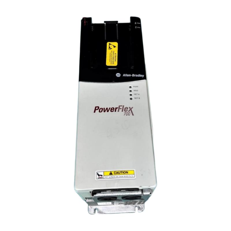
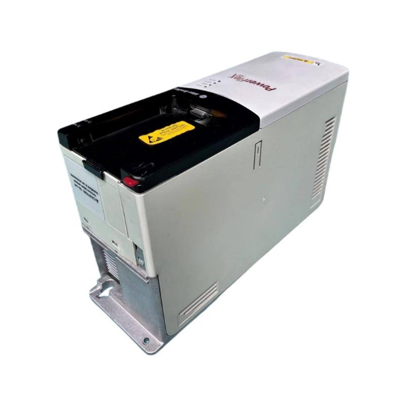
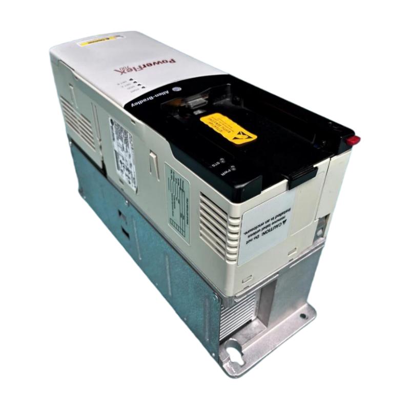
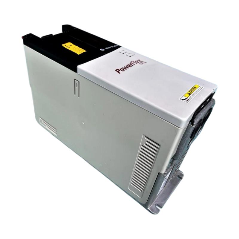
- Allen Bradley
- 20BC3P5A0AYNANC0
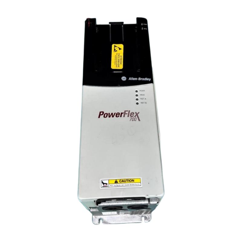
- PowerFlex 700 AC Drive
- USA
- 336 x 200 x 110 mm
- 5.22 kg
- Xiamen, China
- New & In Stock
- T/T, PayPal, Western Union
- 1 Year
- 1-3 Working Days
- DHL, UPS, TNT, FedEx and EMS.
- 24-Hour Service
- COO
- 5
Our advantage

Global Logistics
We have a 10-year logistics and express cooperation agreement, so our products can be shipped to any place in the world.

Brand new and original
Our products are imported in bulk from the place of origin. Because of the cooperative relationship, our products are all original and 100% new.

24-hour service
We provide 7*24 hours service to our customers. We will be there whenever you need us.

Price advantage
All our products are priced very favorably because we have our own warehouse and supply.
| Company Information | |||
| [email protected] | |||
| Mobile | +8615980777398 | ||
| +8615980777398 | |||
| 15980777398 |
Product Overview
The Allen-Bradley 20BC3P5A0AYNANC0 PowerFlex 700 AC Drive is an industrial adjustable-frequency drive designed to provide variable-speed control for compatible three-phase AC motors. Manufactured by Rockwell Automation under the Allen-Bradley brand, this drive belongs to the PowerFlex 700 family, which has been widely used in industrial automation, manufacturing equipment, and motor-control applications.
Variable frequency drives regulate motor operation by adjusting the frequency and voltage supplied to the motor. This allows equipment to operate at different speeds according to production requirements, helping improve process coordination and reduce unnecessary mechanical stress. Depending on the application, adjustable-speed control can also contribute to more efficient operation and smoother motor starting and stopping.
The 20BC3P5A0AYNANC0 is rated for a nominal 400 V AC three-phase supply. It provides a continuous output current of 3.5 A, with a normal-duty power rating of 1.5 kW and a heavy-duty power rating of 1.1 kW. These ratings make it suitable for appropriately sized motors in compact industrial machinery, conveyor systems, auxiliary pumping equipment, and other applications requiring adjustable motor speed.
This model features vector control with 24 V DC I/O, conformal coating, an installed braking IGBT, and an EMC filter with a common-mode choke. It does not include a local human interface module (HIM), an internal braking resistor, an internal communication module, or a feedback option.
These configuration details are important when selecting the drive for a new installation or replacement project. A PowerFlex 700 drive with a similar power rating may have different control interfaces, braking hardware, or environmental features. The complete catalog number should therefore be verified before ordering.
The PowerFlex 700 20B series has been discontinued. However, existing installations may continue to require compatible spare drives for maintenance and equipment restoration. Accurate model identification, electrical verification, and condition assessment are important when sourcing this model through the industrial spare-parts market.
Technical Specifications
| Parameter | Specification |
|---|---|
| Brand | Allen-Bradley |
| Manufacturer | Rockwell Automation |
| Model Number | 20BC3P5A0AYNANC0 |
| Product Series | PowerFlex 700 |
| Product Type | AC Drive / Variable Frequency Drive |
| Input Voltage | 400 V AC nominal |
| Input Phase | Three-phase |
| Nominal Supply Frequency | 50 Hz |
| Continuous Output Current | 3.5 A |
| Normal-Duty Power Rating | 1.5 kW |
| Heavy-Duty Power Rating | 1.1 kW |
| Control Method | Vector control |
| Control I/O | 24 V DC I/O |
| Enclosure Rating | IP20 / NEMA Type 1 |
| Conformal Coating | Included |
| Braking IGBT | Installed |
| Internal Braking Resistor | Not included |
| EMC Filtering | EMC filter with common-mode choke |
| Human Interface Module | Not installed; blank plate |
| Internal Communication Module | Not included |
| Feedback Option | Not included |
| Dimensions Provided | 336 × 200 × 110 mm |
| Weight Provided | 5.22 kg |
| Lifecycle Status | Discontinued |
| Typical Application | Industrial variable-speed motor control |
Specifications should be checked against the actual nameplate and hardware revision before installation. The supplied dimensions and weight are retained for product-listing purposes.
Function and Working Principle
The PowerFlex 700 AC drive converts incoming electrical power into a controlled output suitable for operating an AC motor. Its power electronics and control functions regulate the output according to the selected motor-control method, programmed parameters, and operating commands.
1. Variable-Frequency Speed Regulation
The speed of an AC motor is related to the frequency of the electrical supply and the motor’s design. By changing the output frequency, the drive allows a motor to operate at different speeds within its permitted operating range.
In a conveyor application, for example, a motor may need to run slowly during product positioning and faster during normal material transportation. The drive can adjust the motor speed according to the control system’s requirements.
This flexibility is useful when machinery must respond to changing production rates, material flow, or operating conditions.
2. Vector Control
The 20BC3P5A0AYNANC0 is configured with vector control and 24 V DC I/O. Vector-control methods provide more sophisticated motor regulation than basic frequency-only control.
When correctly configured for the connected motor, vector control can support improved torque response and speed regulation. This can be beneficial in applications where the load changes during operation or where the motor must maintain predictable performance during acceleration and deceleration.
Actual performance depends on motor characteristics, parameter settings, tuning, and the mechanical load. Correct commissioning is therefore essential.
3. Acceleration and Deceleration Control
The drive supports independently programmable acceleration and deceleration times. These settings define how quickly the motor moves between operating speeds.
Appropriate ramp settings can help reduce sudden mechanical movement, minimize stress on belts and couplings, and support smoother production sequences.
Deceleration settings must be selected carefully. High-inertia loads may regenerate energy when slowing down, potentially increasing the drive’s DC bus voltage. Because this model does not include an internal braking resistor, the braking arrangement must be assessed when rapid or frequent stopping is required.
4. Motor Protection and Fault Monitoring
The PowerFlex 700 includes protection and diagnostic functions intended to identify abnormal operating conditions. Depending on the drive configuration and application, these functions can help detect overcurrent, voltage abnormalities, overheating, and motor overload conditions.
Correct motor data and parameter settings are important for reliable protection. The drive does not replace the need for appropriate upstream circuit protection, grounding, isolation, and application-specific safety measures.
5. Electromagnetic Compatibility
The specified configuration includes an EMC filter with a common-mode choke. These components help manage electromagnetic interference when the drive is installed and wired in accordance with the manufacturer’s instructions.
Grounding, cable shielding, cable routing, and cabinet design also influence electromagnetic compatibility. The presence of an EMC filter does not guarantee compliance under every installation condition.
Role in Industrial Control Systems
The 20BC3P5A0AYNANC0 can serve as the motor-control component within a wider automation system. It is typically installed between the electrical supply and the motor, receiving commands from a PLC or another suitable control arrangement.
PLC Integration
A programmable logic controller can coordinate the drive with sensors, actuators, interlocks, and other machinery. Depending on the installation, the PLC may issue start and stop commands, set a speed reference, or change operating conditions in response to process signals.
This drive has 24 V DC I/O but does not include an internal communication module in the specified configuration. Engineers should confirm the actual control interface and required hardware rather than assume a particular network connection is available.
HMI and Operator Control
A human-machine interface can provide operators with access to process information, alarm messages, and machine commands. In many industrial systems, the HMI communicates with the PLC, which then manages drive operation.
The 20BC3P5A0AYNANC0 is supplied without an installed HIM. If local access is required for commissioning, parameter adjustment, or troubleshooting, the appropriate interface and programming method should be confirmed before installation.
Motor and Process Coordination
The drive can be used in a control strategy that adjusts motor speed according to production needs. A PLC might regulate conveyor speed based on product flow or coordinate a motor with an upstream machine.
The drive itself does not replace the PLC, sensors, or mechanical control components. Reliable operation depends on the entire system being correctly designed, configured, and tested.
Industrial Applications
The PowerFlex 700 family is designed for industrial motor-control applications. The 20BC3P5A0AYNANC0 provides a continuous output current of 3.5 A and a normal-duty power rating of 1.5 kW, so application suitability must be evaluated against the motor’s current, power, load characteristics, and operating duty.
1. Conveyor Systems
Conveyors often require adjustable speed to coordinate material movement with inspection, sorting, packaging, or downstream processing equipment.
A correctly selected drive can provide controlled acceleration and deceleration while allowing the motor to operate at different production speeds. The motor’s rated current, starting torque, conveyor inertia, and stopping requirements should be checked before installation.
2. Pumping Equipment
Industrial pumping systems may need variable flow or pressure control. In suitable applications, a variable frequency drive can adjust pump speed to match process demand and reduce the need for mechanical throttling.
The pump’s operating range, motor ratings, cooling requirements, and fluid characteristics should be considered when selecting and configuring the drive.
3. Fans and Ventilation Systems
Fans and ventilation equipment can benefit from adjustable-speed control when airflow requirements vary. Operating a fan at a lower speed may reduce energy consumption under suitable conditions.
The drive must be matched to the motor and fan load. Cabinet ventilation, ambient temperature, and electrical installation requirements should also be considered.
4. Packaging and Assembly Machinery
Packaging and assembly equipment may use adjustable-speed motors for feeding, conveying, or auxiliary movement. Drive-controlled speed changes can help coordinate different stages of a production cycle.
For applications requiring precise positioning or closed-loop speed control, engineers should verify whether the available control configuration and absence of a feedback option meet the required performance.
5. General Manufacturing Equipment
The drive may be suitable for compatible motors in compact manufacturing machinery, material-handling systems, and auxiliary process equipment.
Its suitability should be determined using motor nameplate data, load characteristics, duty cycle, environmental conditions, and control requirements. The rated kilowatt value alone is not sufficient to establish compatibility.
Installation and System Integration
Correct installation is essential for electrical safety, stable operation, and long-term reliability.
1. Verify Electrical Compatibility
Confirm that the incoming supply matches the drive’s nominal 400 V AC three-phase rating. Check the supply frequency, motor voltage, motor current, and upstream protective-device requirements.
The motor’s current and overload demands must remain within the drive’s ratings. A motor with a similar power rating may still be unsuitable if its current or starting requirements exceed the drive’s capability.
2. Confirm Mounting Dimensions and Clearances
The supplied dimensions are 336 × 200 × 110 mm. Verify the manufacturer’s dimensional drawing for the exact unit before designing a control panel or mounting bracket.
Allow sufficient space for airflow, wiring, inspection, and maintenance. The cabinet should provide appropriate heat dissipation and protection against environmental contaminants.
The IP20 / NEMA Type 1 configuration is not a sealed, water-resistant enclosure. Where moisture, conductive dust, or corrosive contaminants may be present, use a suitable protective cabinet and follow the manufacturer’s environmental requirements.
3. Wiring and Grounding
Install power, motor, control, and grounding conductors according to the manufacturer’s instructions and applicable electrical codes. Separate sensitive control wiring from power conductors where required to reduce electrical interference.
Use appropriately rated conductors and protective devices. Before working on the drive, isolate the electrical supply, follow lockout procedures, and verify that hazardous voltage has been removed.
4. Motor Parameter Configuration
Enter the correct motor nameplate information and configure the control method, command source, speed reference, acceleration and deceleration times, and applicable protection parameters.
For vector-control operation, follow the prescribed motor setup and tuning procedure. Incorrect parameter settings may lead to poor speed regulation, inadequate torque response, or nuisance trips.
5. Braking System Assessment
The 20BC3P5A0AYNANC0 includes a braking IGBT but does not include an internal braking resistor. These components perform different functions: the IGBT switches the braking circuit, while a resistor dissipates regenerated energy when required.
Applications involving rapid stopping, repeated deceleration, or high-inertia loads may require an approved external braking resistor or another suitable braking arrangement. Verify the braking requirements, resistor rating, duty cycle, wiring, and protection against the manufacturer’s documentation.
6. Commissioning and Functional Testing
Before returning the equipment to service, inspect the wiring, grounding, and motor connections. Verify that the motor can rotate safely and that the configured control method matches the application.
Test start and stop commands, rotation direction, speed references, acceleration and deceleration, interlocks, and fault response. Record the final parameter settings to support future maintenance and replacement.
Compatible System Components
The drive is typically installed as part of a complete motor-control system. The compatibility of each component depends on its electrical ratings and the system’s control architecture.
| Component | Function | Compatibility Considerations |
|---|---|---|
| Three-phase AC motor | Converts electrical energy into mechanical motion | Verify voltage, current, power, speed, and load requirements |
| PLC | Controls machine sequences and operating commands | Confirm I/O compatibility and the intended drive-control method |
| 24 V DC control supply | Powers compatible control circuits | Check voltage, current capacity, common reference, and wiring |
| HMI | Provides operator access to machine information | May communicate through the PLC; this drive has no installed HIM |
| Circuit breaker or fuses | Provides upstream electrical protection | Select according to manufacturer recommendations and applicable codes |
| Motor isolator | Supports safe electrical isolation | Follow the specified installation and safety procedures |
| External braking resistor | Dissipates regenerated energy when required | This drive has no internal braking resistor; verify the braking design |
| EMC and grounding accessories | Help manage electromagnetic interference | Follow grounding, shielding, and cable-routing requirements |
| Control cabinet | Houses and protects electrical equipment | Provide suitable clearance, airflow, and environmental protection |
These components are examples of equipment that may be used in an installation. They are not necessarily supplied with the drive.
Alternative Models and Replacement Considerations
The PowerFlex 700 20B series has been discontinued. When sourcing a replacement, engineers should compare electrical ratings and configuration details rather than relying on the product-family name alone.
| Alternative or Related Option | Replacement Considerations |
|---|---|
| Another PowerFlex 700 drive | Confirm the full catalog number, voltage, output current, control method, and installed options |
| Allen-Bradley PowerFlex 70 | May be considered for selected applications after a detailed technical review |
| Allen-Bradley PowerFlex 525 | A newer drive family for some applications, but not automatically a direct replacement |
| Allen-Bradley PowerFlex 4M or another compact drive | May suit simpler applications if electrical and control requirements are met |
| Current-generation Rockwell Automation drive | May be suitable for a modernization project, potentially requiring engineering changes |
Before approving a replacement, compare:
- Input voltage and phase configuration.
- Continuous output current and overload capability.
- Normal-duty and heavy-duty power ratings.
- Motor-control method and speed-regulation requirements.
- Control I/O voltage and terminal assignments.
- Communication and feedback requirements.
- Braking IGBT and braking-resistor configuration.
- EMC filtering and environmental protection.
- Mounting dimensions, cooling, and wiring access.
- PLC program, parameter settings, and commissioning procedures.
A drive with a similar power rating may not provide the same functions. A replacement may require wiring modifications, parameter conversion, control-program changes, or recommissioning.
Key Advantages
Flexible Motor-Speed Control
The drive supports adjustable-speed operation for compatible AC motors, helping machinery respond to changing production requirements.
Vector-Control Capability
Its vector-control configuration supports more advanced motor regulation when correctly configured for the connected motor and load.
Programmable Acceleration and Deceleration
Adjustable ramp settings allow engineers to adapt motor response to process requirements and help reduce abrupt mechanical movement.
Integrated Braking IGBT
The installed braking IGBT provides a braking-circuit capability. Additional braking hardware may be necessary depending on the application’s stopping and energy-dissipation requirements.
EMC Filtering
The included EMC filter with common-mode choke supports electromagnetic compatibility when the drive is installed and wired correctly.
Conformal Coating
The specified configuration includes conformal coating for the electronic assemblies. This feature can provide additional protection under suitable environmental conditions, but it does not make the drive suitable for unrestricted exposure to moisture or corrosive substances.
Established Industrial Application
The PowerFlex 700 series is used in existing industrial installations. Accurate model identification and configuration matching can help maintenance teams source compatible spare parts and plan equipment upgrades.
Technical FAQs
1. What is the Allen-Bradley 20BC3P5A0AYNANC0?
It is a PowerFlex 700 AC drive designed for variable-speed control of compatible three-phase motors. Its nominal input rating is 400 V AC, with a continuous output current of 3.5 A.
2. What is the rated power of this drive?
The drive is rated at 1.5 kW for normal-duty operation and 1.1 kW for heavy-duty operation. The appropriate rating depends on the load and required overload performance.
3. What input voltage does the model require?
It is designed for a nominal 400 V AC three-phase supply at 50 Hz. Confirm the actual nameplate and installation documentation before connecting power.
4. Does it include a braking resistor?
No. The model includes a braking IGBT but does not include an internal braking resistor. An external braking arrangement may be necessary for applications involving significant regenerative energy.
5. Does the drive have an internal communication module?
No internal communication module is included in this catalog configuration. Confirm the intended control interface and any additional hardware requirements before designing the system.
6. Can the drive work with a PLC?
Yes. It can be integrated into a suitable PLC-based system using its configured 24 V I/O and an appropriate control arrangement. The exact wiring and command method must be verified for the application.
7. Is the PowerFlex 700 20B series still in production?
No. Rockwell Automation announced discontinuation of the PowerFlex 700 20B series effective November 30, 2023. Availability of this specific model depends on remaining inventory and the industrial spare-parts market.
8. Can this model replace another PowerFlex 700 drive?
Not automatically. Differences in voltage, current, power, control interfaces, braking components, filtering, and feedback options can affect compatibility. Compare the complete catalog numbers before substitution.
9. What should be checked when purchasing a used drive?
Verify the nameplate, complete catalog number, series, visible condition, terminals, cooling fan, and available test information. Confirm whether accessories are included and request suitable functional testing for critical applications.
10. Are the dimensions and weight suitable for a product listing?
The supplied dimensions of 336 × 200 × 110 mm and weight of 5.22 kg are consistent with published physical data for this model. For shipping purposes, distinguish the drive’s net weight from the total packaged weight.
Procurement and Maintenance Recommendations
Because the PowerFlex 700 20B series has been discontinued, procurement should begin with exact catalog-number verification. Searching by the product family name alone may return drives with different electrical ratings or configuration options.
When sourcing the 20BC3P5A0AYNANC0, verify the 400 V AC input rating, 3.5 A output current, 1.5 kW normal-duty rating, 1.1 kW heavy-duty rating, vector-control configuration, conformal coating, EMC filtering, and braking arrangement.
For new-old-stock, used, or refurbished units, request clear photographs of the nameplate and terminals. Confirm the unit’s condition, testing status, included accessories, warranty terms, and return policy. Verify shipping dimensions and packaged weight separately when preparing international freight documentation.
During maintenance, keep the drive and surrounding cabinet clean, maintain adequate airflow, and inspect wiring, terminals, grounding, and cooling components according to the applicable maintenance schedule. Back up parameter settings and document any changes made during troubleshooting or commissioning.
When planning a replacement, assess whether the existing motor, PLC logic, control wiring, braking arrangement, and panel layout can be retained. A newer drive may require parameter conversion, wiring changes, software updates, or a new commissioning procedure.
Conclusion
The Allen-Bradley 20BC3P5A0AYNANC0 PowerFlex 700 AC Drive is a 400 V AC three-phase variable frequency drive with a continuous output current of 3.5 A, a 1.5 kW normal-duty rating, and a 1.1 kW heavy-duty rating. Its specified configuration includes vector control with 24 V DC I/O, conformal coating, an installed braking IGBT, and EMC filtering.
The drive does not include an internal braking resistor, an installed HIM, or an internal communication module. Since the PowerFlex 700 20B series has been discontinued, accurate model identification and compatibility assessment are important for industrial maintenance and replacement projects.