
NewsNEWCENTER
Featured products

Contact Us
Allen-Bradley 1746SC-INI4VI SLC 500 Isolated Analog Input Module: Installation, Wiring, Configuration, and Commissioning Guide
2026-10-26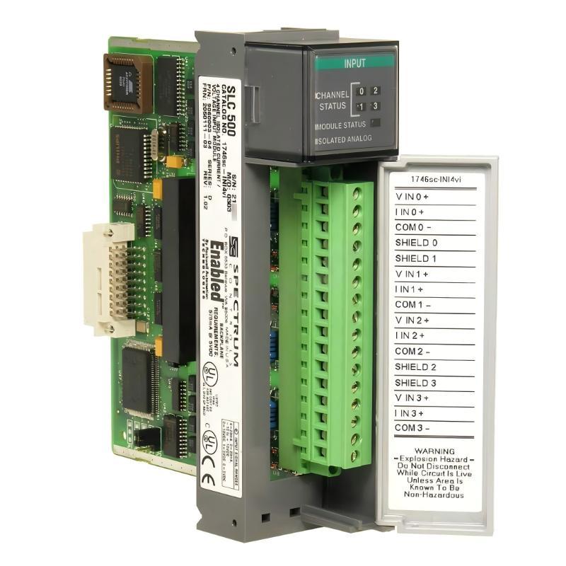
The Allen-Bradley 1746SC-INI4VI SLC 500 Isolated Analog Input Module is a four-channel analog input module designed to measure industrial voltage and current signals in PLC-based automation systems. It supports independently configurable input channels and electrical isolation, making it suitable for applications where process measurement accuracy, signal flexibility, and protection against electrical interference are important.
This installation guide explains how to prepare the SLC 500 chassis, install the module, connect analog transmitters, configure channel ranges, integrate measurements into the PLC program, and commission the system. It is intended for automation engineers, instrumentation technicians, maintenance teams, and system integrators working with existing Allen-Bradley SLC 500 installations.
Table of Contents
- Product Overview
- Technical Specifications
- Pre-Installation Preparation
- Module Installation Procedure
- Analog Signal Wiring
- Channel Configuration and PLC Integration
- Commissioning and Signal Verification
- Maintenance and Reliability
- Frequently Asked Questions
- Technical Summary
1. Product Overview
The 1746SC-INI4VI is an isolated analog input module associated with the SLC 500 I/O platform. It provides four differential analog input channels, each individually isolated. Each channel can be configured for a supported current or voltage range, allowing different types of instrumentation signals to be connected to the same module when the application requires them.
Typical input devices include pressure transmitters, temperature transmitters with analog outputs, flow meters, level transmitters, and other industrial instruments that provide compatible analog signals. The module converts incoming analog signals into digital values that the PLC processor can use for monitoring, alarming, sequencing, calculations, and closed-loop control.
Its software-configurable channels eliminate the need to select every signal range using physical DIP switches. Engineers can configure input ranges, filtering, and data representation through the supported SLC 500 configuration method. The module also provides status information that can assist with identifying configuration and input-related problems.
Typical applications
- Monitoring pressure, flow, level, and temperature transmitters.
- Reading industrial instruments that provide 4–20 mA or 0–20 mA signals.
- Measuring compatible voltage signals from sensors and signal conditioners.
- Acquiring process data for PLC alarms, trends, and control sequences.
- Integrating analog instrumentation into existing SLC 500 control panels.
2. Technical Specifications
| Parameter | Specification |
|---|---|
| Manufacturer / brand | Allen-Bradley-compatible SLC 500 module by Spectrum Controls |
| Model | 1746SC-INI4VI |
| Product family | SLC 500 |
| Module type | Isolated analog input module |
| Number of channels | 4 differential, individually isolated channels |
| Current input ranges | 0–20 mA and 4–20 mA |
| Voltage input ranges | -10 to +10 V DC, 0–10 V DC, 0–5 V DC, and 1–5 V DC |
| Input range selection | Independently configurable by channel |
| Conversion method | Sigma-delta analog-to-digital conversion |
| Resolution | Up to 16 bits, depending on configuration |
| Channel-to-channel isolation | 750 V DC, as specified in the manufacturer’s test conditions |
| Field-wiring-to-backplane isolation | 750 V DC, as specified in the manufacturer’s test conditions |
| Typical backplane current consumption | 550 mA at 5 V DC |
| Module installation location | Compatible 1746 I/O chassis slot, excluding slot 0 |
| Configuration method | Software configuration through the supported SLC 500 environment |
Important: Verify the exact catalog number, hardware revision, input ranges, isolation specifications, and module identification code against the documentation for the installed unit. Do not confuse the INI4VI with the INI4I model, which is intended for current inputs rather than the same combination of current and voltage inputs.
3. Pre-Installation Preparation
3.1 Review the control system
Before installation, confirm that the module is supported by the installed SLC 500 chassis and processor configuration. Check the available slot, the chassis power budget, the analog input requirements, and the controller’s I/O configuration. The 1746SC-INI4VI is designed for an I/O slot other than slot 0; verify the actual chassis layout before selecting its location.
3.2 Prepare the instrumentation data
Prepare an input schedule that identifies each transmitter, its measurement range, output signal type, cable route, and intended PLC tag. For example, a pressure transmitter may use a 4–20 mA output, while another instrument may provide a voltage signal. Each channel must be configured to match the connected device.
3.3 Prepare tools and materials
- Approved electrical test meter and suitable current-measurement equipment.
- Compatible SLC 500 chassis and module terminal block.
- Shielded twisted-pair instrumentation cable appropriate for the application.
- Compatible analog transmitters, signal conditioners, and power supplies.
- Current electrical drawings, loop diagrams, and I/O schedules.
- Supported PLC programming and configuration software.
- Electrostatic discharge protection for handling the module.
3.4 Apply safety precautions
Isolate the chassis and relevant field circuits before installation or wiring. Follow the site’s lockout/tagout procedure and verify the absence of hazardous voltage. Some transmitters use separate field supplies, so switching off the PLC chassis does not necessarily de-energize the instrument wiring.
Use electrostatic discharge precautions when handling the module. Never alter internal jumpers or components unless the manufacturer explicitly identifies them as user-adjustable; manufacturer-only settings must remain unchanged.
4. Module Installation Procedure
Step 1: Inspect the chassis and module
Check the module label to confirm that the catalog number is 1746SC-INI4VI. Inspect the circuit board, connector, retaining features, and terminal block for visible damage. Confirm that the chassis is securely mounted and that the selected slot is appropriate for the system configuration.
Step 2: Select a suitable slot
Install the module in a compatible 1746 I/O slot other than slot 0. Consider cabinet temperature and electrical noise when choosing the location. Where possible, avoid placing sensitive analog input modules immediately beside equipment that generates significant heat or electrical interference.
Step 3: Insert the module
- Verify that chassis power and relevant field circuits are isolated.
- Align the module with the chassis card guides.
- Slide the module into the slot without forcing it.
- Ensure that it is fully seated in the backplane connector.
- Secure the module using the appropriate retaining hardware.
If the module does not seat smoothly, stop and check the alignment and connector condition. Forcing a module into the chassis can damage the backplane or the module’s connector.
Step 4: Prepare the terminal block
Verify that the terminal block is compatible and in good condition. Identify the channel terminals and their positive and negative input connections using the correct wiring diagram. Keep conductors labeled so that each field signal can be traced to its associated channel.
5. Analog Signal Wiring
5.1 Understand differential inputs and isolation
The 1746SC-INI4VI provides four differential, individually isolated input channels. Differential measurement uses the designated positive and negative input terminals for each signal. The channel isolation helps reduce unwanted electrical interaction between field circuits and the PLC backplane, but it does not remove the need for correct wiring, suitable grounding, or compliance with the module’s electrical ratings.
Use the model-specific terminal diagram to identify the connections for each channel. Do not infer terminal assignments from another SLC 500 analog module.
5.2 Connect 4–20 mA and 0–20 mA transmitters
For current-loop applications, verify the transmitter’s output type and supply requirements before connecting it. A two-wire transmitter typically receives power through the loop, while a three-wire or four-wire instrument may have a different supply and signal arrangement.
The following illustration shows a simplified current-loop concept only. It is not a model-specific terminal diagram.
Compatible loop supply
        |
        v
Current-output transmitter
        |
        v
1746SC-INI4VI configured current input
        |
        v
Correct loop return
Check the manufacturer’s wiring diagrams for the transmitter and input module together. Incorrect loop polarity, an unsuitable supply, or an open return circuit can cause a zero or invalid reading.
5.3 Connect voltage transmitters
For voltage input applications, select one of the supported voltage ranges that covers the instrument’s output. Supported ranges include -10 to +10 V DC, 0–10 V DC, 0–5 V DC, and 1–5 V DC.
Verify signal polarity and connect the signal to the designated differential input terminals. Confirm that the source output does not exceed the permitted input range. Never apply an AC signal or an uncontrolled external voltage to the analog terminals.
5.4 Route and shield instrumentation cables
- Use shielded twisted-pair cable appropriate for the signal type and installation environment.
- Separate low-level analog wiring from motor, contactor, and high-current power wiring where practical.
- Follow the plant’s grounding standard for cable shields.
- Avoid creating unintended ground loops through multiple shield connections.
- Secure cables to prevent movement, abrasion, and strain at the terminal block.
- Keep wiring labels consistent with the loop drawings and PLC tag names.
Shielding practices depend on the complete control-system grounding design. Do not connect cable shields indiscriminately at both ends or leave them floating without considering the applicable installation standard.
5.5 Inspect the wiring before energizing
- Compare each wire with the loop diagram and module terminal assignment.
- Verify channel polarity and input type.
- Check the transmitter supply and loop return.
- Inspect for loose strands, accidental shorts, or damaged insulation.
- Confirm that voltage and current levels are within the applicable input limits.
- Verify that shields and drain wires follow the approved grounding arrangement.
6. Channel Configuration and PLC Integration
6.1 Configure the module identity
The module must be identified correctly in the SLC 500 configuration. The documented module identification code for the 1746SC-INI4VI is 3520. The exact method used to enter or select the ID depends on the programming software version and the controller configuration workflow.
Confirm that the configured module type and ID match the physical hardware. An incorrect slot configuration can prevent the processor from interpreting the module’s data correctly.
6.2 Configure each input channel
Each channel can be configured independently for a supported current or voltage range. Use the appropriate configuration words and bit definitions specified in the module manual. Because the module is software-configurable, do not assume that the channel range is determined by a physical DIP switch.
For every channel, confirm the following:
- Input type: current or voltage.
- Selected signal range.
- Digital data representation.
- Input filtering setting.
- Scaling or engineering-unit conversion.
- Status and error handling.
6.3 Select the appropriate data format
The module supports multiple data representations, including scaled engineering units, PID-oriented scaling, proportional counts, an 1746-NI4-compatible format, and user-defined scaling options. Choose a format appropriate for the PLC program and the application requirements.
When using engineering units, confirm the relationship between the module’s digital value and the physical measurement. For example, a pressure transmitter configured for 0–100 bar must be scaled to that range in the PLC program if the selected data format does not already provide the desired engineering units.
6.4 Configure input filtering
Programmable filtering allows the engineer to balance noise rejection against response speed. The documented filter options include nominal 50 Hz, 60 Hz, 250 Hz, and 500 Hz settings. Lower-frequency filtering can help reject power-line interference, while higher-frequency settings provide a faster response but may allow more signal noise.
Select the filter based on the process dynamics, expected interference, and control-loop requirements. A slow pressure or temperature process may tolerate more filtering than a rapidly changing measurement used for machine control.
6.5 Establish PLC tag mapping
Confirm the relationship between the module slot, channel configuration words, input data words, and the PLC tags used by the application. Use the correct addressing scheme for the installed SLC 500 processor and software version.
| Configuration item | Verification |
|---|---|
| Module identity | Configured module corresponds to 1746SC-INI4VI, ID code 3520. |
| Slot location | Physical and software slot assignments match; slot 0 is excluded. |
| Channel range | Configured input range matches the connected instrument. |
| Data format | PLC logic interprets the returned values correctly. |
| Input filtering | Filter setting matches the response and noise requirements. |
| Scaling | Digital values convert correctly into engineering units. |
| Status handling | Channel or module diagnostics are checked where applicable. |
7. Commissioning and Signal Verification
Step 1: Complete a pre-power inspection
Check the module seating, terminal-block connections, transmitter wiring, supply polarity, and shield grounding. Confirm that all field instruments are suitable for the selected input ranges.
Step 2: Restore power
Restore chassis and instrument power according to the approved startup procedure. Check the processor and module status indicators. Resolve configuration or system faults before relying on the analog readings for process control.
Step 3: Verify each channel individually
- Identify the instrument associated with the first channel.
- Confirm the module’s configured input type and range.
- Apply or observe a known valid signal using an approved test method.
- Check the raw or configured input value in the PLC.
- Verify that the engineering-unit value is correct.
- Repeat the test for all four channels.
Step 4: Verify current and voltage scaling
For a 4–20 mA transmitter, confirm the mapping between the lower and upper current limits and the configured engineering range. For a voltage transmitter, verify the expected value at representative points within the selected range.
Use a calibrated signal source or process calibrator when a formal loop check is required. Follow the instrument and module test procedures, and avoid injecting a signal while the field transmitter remains connected unless the approved test arrangement permits it.
Step 5: Verify alarms and abnormal conditions
Check how the PLC application handles invalid readings, out-of-range values, broken loops, and module status information. Ensure that alarm limits and fallback behavior are appropriate for the process. Do not assume that every fault condition will automatically be detected or handled in the same way; verify the behavior for the selected channel configuration and software.
Step 6: Record commissioning results
Document the module model and revision, slot number, channel ranges, filter settings, transmitter identification, calibration results, and PLC tag mapping. Update the loop drawings and I/O schedule after any configuration changes.
8. Maintenance and Reliability
Regular maintenance helps preserve measurement quality and reduce unplanned downtime in SLC 500 systems.
- Inspect terminal blocks and signal wiring for looseness, corrosion, or physical damage.
- Check transmitter supplies and loop continuity when readings become unstable.
- Review module status and channel diagnostic information when values become abnormal.
- Inspect cable routing and shield grounding if measurements show electrical interference.
- Verify channel configuration after replacing a transmitter or modifying the PLC project.
- Maintain current copies of the controller program, configuration records, and loop diagrams.
- Use calibrated instruments for periodic verification when required by the site’s maintenance plan.
When replacing the module, verify the exact catalog number, supported software configuration, input ranges, isolation characteristics, and terminal arrangement. A current-only analog module is not automatically interchangeable with the INI4VI model, which supports both current and voltage input configurations.
9. Frequently Asked Questions
How many analog inputs does the 1746SC-INI4VI provide?
It provides four differential analog input channels, individually isolated from one another.
Can the 1746SC-INI4VI measure both current and voltage signals?
Yes. Each channel can be configured for a supported current range or, on this VI model, a supported voltage range. The configuration must match the connected instrument.
What current input ranges are supported?
The documented current ranges are 0–20 mA and 4–20 mA. Confirm the selected range in the module configuration before commissioning the loop.
What voltage ranges are supported?
The documented voltage ranges are -10 to +10 V DC, 0–10 V DC, 0–5 V DC, and 1–5 V DC.
What is the module identification code?
The documented module ID code for the 1746SC-INI4VI is 3520. Confirm the correct configuration procedure for the software and processor version in use.
Why is the measured value incorrect even though the transmitter is operating?
Possible causes include an incorrect channel range, reversed or incorrect wiring, poor loop power, unsuitable filtering, incorrect data format, scaling errors, or electrical interference. Verify the signal at the module and compare the raw PLC value with the expected input.
Does channel isolation eliminate all electrical noise?
No. Isolation helps reduce unwanted electrical interaction, but good cable routing, appropriate shielding, correct grounding, and suitable signal wiring remain important.
10. Technical Summary
The Allen-Bradley 1746SC-INI4VI SLC 500 Isolated Analog Input Module provides four individually isolated analog input channels with independently configurable current and voltage ranges. Its software-based configuration, filtering options, and digital signal conversion support process measurement in industrial automation systems.
Successful installation depends on correct chassis placement, careful differential signal wiring, compatible field instruments, accurate channel configuration, and verified PLC scaling. During commissioning, test each channel using a known signal and confirm that the displayed engineering value matches the expected measurement.
For reliable long-term operation, maintain accurate loop drawings, protect analog wiring from electrical interference, monitor diagnostic information, and verify module compatibility before replacement. These practices help maintain dependable process measurements in existing SLC 500 control systems.