
NewsNEWCENTER
Featured products

Contact Us
Allen Bradley 1606-XLB240E Power Supply Installation Guide
2026-08-21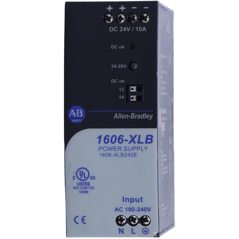
Table of Contents
- Allen Bradley 1606-XLB240E Power Supply Installation Overview
- Allen Bradley 1606-XLB240E Power Supply Role in Industrial Automation
- Allen Bradley 1606-XLB240E Installation Planning and Load Assessment
- Allen Bradley 1606-XLB240E Cabinet Installation and Thermal Planning
- Allen Bradley 1606-XLB240E Wiring and DC Distribution
- Allen Bradley 1606-XLB240E Setup and Pre-Energization Checks
- Allen Bradley 1606-XLB240E Commissioning and System Configuration
- Allen Bradley 1606-XLB240E Load Validation and Acceptance Checks
- Allen Bradley 1606-XLB240E Field Installation Case
- Allen Bradley 1606-XLB240E Installation FAQ
- Allen Bradley 1606-XLB240E Overall Technical Summary
Allen Bradley 1606-XLB240E Power Supply Installation Overview
Allen Bradley 1606-XLB240E installation should be verified as part of the complete industrial DC power system, not simply by checking whether the unit turns on. The key commissioning questions are whether the input circuit is correctly protected, whether the DC output matches the control-system design, whether the distribution wiring can carry the expected load, and whether the PLC Controller and connected Modules receive stable power during real operating conditions.
The 1606-XLB240E is an Allen Bradley industrial power supply intended for control-panel applications. In an automation cabinet, the DC power circuit may support PLC equipment, I/O Modules, communication interfaces, Sensors, relays, instrumentation, and other control devices. A problem in the power-distribution system can therefore appear as a controller fault even when the controller hardware is functioning correctly.
A field-oriented Installation Guide should establish electrical baselines before full commissioning. Measuring the supply output only at the power-supply terminals is not enough; important load-side points should also be checked, especially when the cabinet contains long DC cable runs or multiple branches.
Allen Bradley 1606-XLB240E Power Supply Role in Industrial Automation
Industrial control systems frequently use a common DC bus to supply multiple classes of equipment. The 1606-XLB240E can therefore become part of a larger power architecture rather than serving one isolated device.
From an engineering perspective, the most important distinction is between the calculated load and the actual load behavior. PLC equipment may have a relatively predictable consumption profile, while relays, contactors, solenoids, and other switching devices can create transient demands or electrical disturbances.
Allen Bradley 1606-XLB240E Control-Power Load Considerations
- Calculate the expected continuous current of the complete DC load.
- Identify startup and inrush characteristics of connected devices.
- Separate sensitive control equipment from electrically noisy loads where practical.
- Consider voltage drop on long DC distribution runs.
- Provide suitable branch protection.
- Allow engineering margin for future PLC or I/O expansion.
Allen Bradley 1606-XLB240E Installation Planning and Load Assessment
Before installation, compare the control-panel drawing with the actual equipment list. A power supply may have been selected for an original PLC configuration, while later modifications may have added remote I/O, Sensors, communication equipment, or interface relays.
Calculate the connected load from the actual equipment rather than relying on an old panel label. Pay particular attention to devices that operate intermittently because they may not appear in a basic steady-state current calculation.
Allen Bradley 1606-XLB240E Pre-Installation Checks
- Confirm the exact 1606-XLB240E model designation.
- Verify the designed input power source.
- Confirm the required DC voltage for downstream equipment.
- Calculate normal and expected peak loading.
- Check protective-device selection.
- Review conductor size and expected voltage drop.
- Inspect the cabinet environment.
- Identify critical PLC and instrumentation branches.
Allen Bradley 1606-XLB240E Cabinet Installation and Thermal Planning
Cabinet layout affects long-term power-supply reliability. The 1606-XLB240E should be positioned so that its ventilation path is not unnecessarily restricted by neighboring components, wire ducts, or other heat-generating equipment.
Thermal conditions should be considered together with electrical loading. A cabinet that appears acceptable during a short commissioning test may develop problems after several hours when internal temperature rises and multiple power devices operate continuously.
Mechanical security is also important. Control cabinets installed near pumps, motors, compressors, or other vibrating machinery should receive particular attention during terminal inspection and maintenance.
Allen Bradley 1606-XLB240E Wiring and DC Distribution
Allen Bradley 1606-XLB240E wiring should be completed with the applicable power source isolated and the cabinet prepared according to the site’s electrical safety procedure. Input and DC output conductors should be clearly identified before termination.
Polarity verification is particularly important on the DC side. Do not assume that conductor color is sufficient evidence. Trace each conductor against the approved electrical drawing and verify the result with appropriate test equipment before sensitive equipment is connected.
Allen Bradley 1606-XLB240E DC Wiring Practices
- Use correctly sized conductors for the expected load.
- Keep DC power wiring mechanically secure.
- Separate sensitive signal wiring from high-noise circuits where practical.
- Verify positive and negative DC polarity before energizing loads.
- Inspect all terminal connections before startup.
- Keep branch identification consistent with the electrical drawings.
After wiring is complete, perform a point-to-point inspection. Pay particular attention to unused terminals, branch jumpers, common returns, and any field modifications made after the original panel design.
Allen Bradley 1606-XLB240E Setup and Pre-Energization Checks
The 1606-XLB240E Setup process should progress from the incoming supply toward the final loads. Before full system energization, verify the input circuit and inspect the DC distribution for unintended connections.
Where the panel design permits staged commissioning, initially check the power supply with a controlled or minimal downstream load. Measure the output directly at the supply and establish a baseline before connecting the complete automation system.
Allen Bradley 1606-XLB240E initial check:

Input:
  verify source voltage
  verify protective device
  verify wiring integrity

Output:
  measure VDC at supply terminals
  measure VDC at distribution point
  compare both readings

If readings are consistent:
  energize essential PLC loads
  monitor DC voltage
  add branches progressively
  repeat measurements during load switching
Allen Bradley 1606-XLB240E Commissioning and System Configuration
Commissioning should confirm that the 1606-XLB240E performs correctly with the intended System Configuration. The PLC Controller should start normally, connected I/O Modules should remain available, and communication equipment should operate without unexplained resets.
Introduce the load progressively when practical. This approach provides useful diagnostic information because each newly energized branch can be associated with its effect on the DC bus.
Allen Bradley 1606-XLB240E Commissioning Measurements
- Record the incoming supply voltage.
- Record the DC output voltage at the 1606-XLB240E.
- Measure the main DC distribution voltage.
- Measure a remote critical load where applicable.
- Observe PLC Controller operation.
- Monitor I/O Module and communication status.
- Operate representative switching loads.
- Repeat key measurements after the cabinet reaches normal operating temperature.
Allen Bradley 1606-XLB240E Load Validation and Acceptance Checks
A successful commissioning result requires more than a normal no-load measurement. The power circuit should be validated under the conditions in which the automation system will actually operate.
For example, if a remote I/O cabinet is located at the end of a long DC cable, measure voltage at that remote point while the connected equipment is operating. A stable voltage at the 1606-XLB240E does not automatically prove that the remote device receives the same voltage.
Allen Bradley 1606-XLB240E System Validation Data
- Input voltage under normal operation.
- Power-supply output voltage.
- Main DC bus voltage.
- Remote load voltage.
- PLC Controller operating status.
- I/O Module status.
- Communication stability.
- Voltage response during switching events.
Allen Bradley 1606-XLB240E Field Installation Case
In one commissioning case, the 1606-XLB240E was installed in a control cabinet supporting a PLC Controller and several distributed field circuits. The initial measurement at the power-supply output was approximately 24 VDC, and the PLC started normally.
During staged commissioning, additional field-interface branches were energized. A remote I/O group then showed intermittent behavior when several actuator circuits were activated simultaneously.
The engineer did not immediately replace the power supply. Instead, the voltage was measured at both the 1606-XLB240E terminals and the remote distribution point during the same switching event. The supply terminal voltage remained relatively stable, while the remote point experienced a significantly greater voltage reduction.
Inspection of the affected distribution branch identified a high-resistance connection. Under light load, the connection produced little obvious symptom. Once several loads operated simultaneously, however, the additional current caused a measurable voltage drop.
After correcting the connection and repeating the commissioning sequence, the remote I/O equipment remained stable. The case reinforced a practical engineering rule: always compare source-side and load-side measurements before identifying a DC power supply as the failed component.
Allen Bradley 1606-XLB240E Installation and Commissioning FAQ
What should be checked before Allen Bradley 1606-XLB240E installation?
Verify the model, input supply, required DC output, load calculation, protective devices, conductor sizing, cabinet environment, grounding arrangement, and downstream System Configuration.
Why is staged commissioning useful for the 1606-XLB240E?
Staged commissioning makes it easier to identify which load branch affects the DC system. If the voltage changes immediately after one group is connected, that branch becomes a logical point for further investigation.
Can long DC cables affect PLC operation?
Yes. Cable resistance can create voltage drop, particularly when current increases. A PLC Controller or remote I/O Module may therefore receive a lower voltage than the measurement taken directly at the power supply.
What measurements are useful during 1606-XLB240E Setup?
Measure the input voltage, supply output voltage, main DC distribution voltage, and voltage at important remote loads. Compare these measurements under both light-load and representative operating conditions.
How does good commissioning help future Troubleshooting?
Commissioning records establish a normal electrical baseline. During future Fault Diagnosis, maintenance personnel can compare new measurements with the original values and identify changes more quickly.
Allen Bradley 1606-XLB240E Overall Technical Summary
The Allen Bradley 1606-XLB240E Installation Guide should be applied to the complete control-power architecture. Correct wiring, protection, cabinet layout, thermal management, and load planning establish a sound installation, while measured Setup and Commissioning prove that the DC system performs correctly under actual operating conditions.
For field engineers, one of the most valuable practices is comparing voltage at the 1606-XLB240E with voltage at critical downstream equipment. This simple diagnostic method can expose distribution resistance, overloaded branches, and poor connections before they develop into intermittent PLC or I/O faults.
With appropriate System Configuration, documented commissioning measurements, and load-side validation, the 1606-XLB240E can provide a reliable DC power foundation for PLC Controllers, Modules, Sensors, communication equipment, and other industrial automation devices.
“`