
NewsNEWCENTER
Featured products

Contact Us
Allen Bradley 1606-XLB120E/A Power Supply Installation Guide
2026-08-20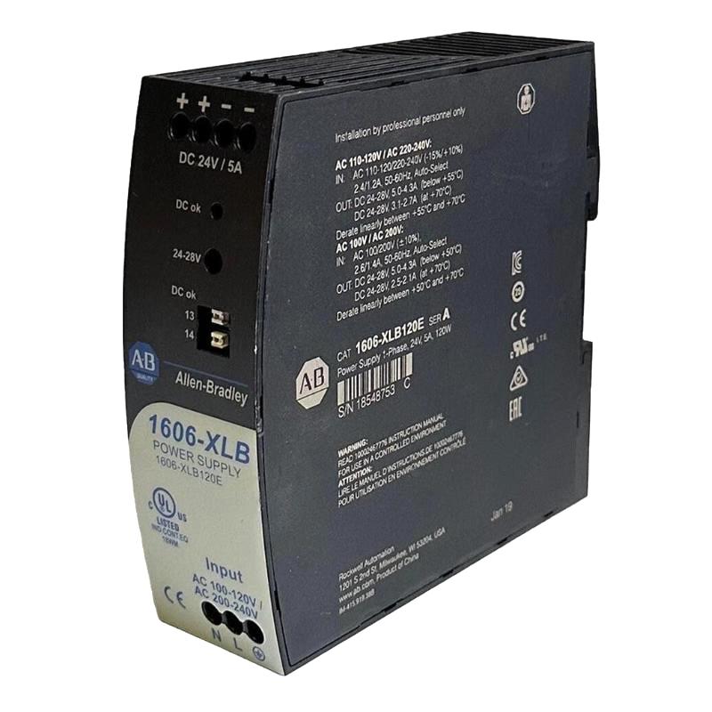
Table of Contents
- Allen Bradley 1606-XLB120E/A Power Supply Installation Overview
- Allen Bradley 1606-XLB120E/A Power Supply Engineering Role
- Allen Bradley 1606-XLB120E/A Installation Pre-Checks
- Allen Bradley 1606-XLB120E/A Cabinet Mounting and Layout
- Allen Bradley 1606-XLB120E/A Wiring and DC Distribution
- Allen Bradley 1606-XLB120E/A Setup and Initial Energization
- Allen Bradley 1606-XLB120E/A Commissioning and System Configuration
- Allen Bradley 1606-XLB120E/A Load Validation
- Allen Bradley 1606-XLB120E/A Field Commissioning Case
- Allen Bradley 1606-XLB120E/A Installation FAQ
- Allen Bradley 1606-XLB120E/A Overall Technical Summary
Allen Bradley 1606-XLB120E/A Power Supply Installation Overview
Allen Bradley 1606-XLB120E/A installation should be verified at three levels: the incoming power circuit, the power-supply output, and the actual DC loads. A power supply can show a normal output at its own terminals while a remote PLC Controller, I/O Module, or Sensor receives an unstable voltage because of distribution resistance, excessive load, or a poor terminal connection.
The 1606-XLB120E/A is an Allen Bradley industrial power supply used in control-panel environments where dependable DC power is required. Its installation therefore affects the stability of the wider automation system, including PLC processors, I/O equipment, communication interfaces, sensors, relays, and other control devices.
A practical Installation Guide should focus on measurable results. Correct Setup and Commissioning means proving that the 1606-XLB120E/A operates correctly under the intended load and that the DC voltage remains suitable at the equipment being powered.
Allen Bradley 1606-XLB120E/A Power Supply Engineering Role
Within a typical automation cabinet, the power supply establishes the DC control bus used by several different classes of equipment. Some loads are electrically quiet, while others can introduce switching disturbances. This distinction becomes important when designing the System Configuration.
PLC Controllers and communication equipment are generally more sensitive to short-duration voltage disturbances than many simple relay loads. For this reason, power distribution should be considered together with the control architecture rather than treating every DC consumer as an identical load.
Allen Bradley 1606-XLB120E/A Load Planning
- Calculate the normal operating current of connected equipment.
- Identify startup and switching loads.
- Separate critical control circuits from high-noise loads where appropriate.
- Consider voltage drop on long DC cable runs.
- Provide suitable branch protection.
- Allow capacity for planned system expansion.
Allen Bradley 1606-XLB120E/A Installation Pre-Checks
Before mounting or wiring the 1606-XLB120E/A, compare the physical unit with the electrical documentation. Confirm that the model designation is correct and that the intended application matches the designed input and DC distribution requirements.
Inspect the enclosure and terminal area for mechanical damage, contamination, moisture, or loose components. If the power supply is being installed in an existing cabinet, inspect the surrounding equipment as well. A new power supply cannot compensate for an overloaded or poorly designed distribution circuit.
Allen Bradley 1606-XLB120E/A Installation Checklist
- Confirm the 1606-XLB120E/A model and revision marking.
- Verify the designed input supply.
- Confirm the required DC output for connected equipment.
- Calculate the expected total load.
- Check protective devices and conductor sizing.
- Review cabinet ventilation and ambient conditions.
- Confirm the grounding arrangement.
- Identify the critical PLC and instrumentation loads.
Allen Bradley 1606-XLB120E/A Cabinet Mounting and Layout
The mounting location should allow adequate airflow and practical access to the wiring terminals. Avoid positioning the 1606-XLB120E/A directly in a concentrated hot-air path created by other power electronics.
Good cabinet layout also reduces troubleshooting time. Input wiring, DC distribution, and sensitive signal circuits should have clear routing paths so that an engineer can trace the electrical system without ambiguity.
Where the cabinet is installed near motors or other sources of mechanical vibration, the mechanical security of the power supply and its conductors deserves additional attention. A connection that is electrically acceptable during factory testing can become intermittent after prolonged vibration.
Allen Bradley 1606-XLB120E/A Wiring and DC Distribution
Allen Bradley 1606-XLB120E/A wiring should be completed with the relevant power source isolated. Identify input, DC output, and protective-earth connections from the unit markings and the approved electrical design.
Before connecting the PLC Controller or other sensitive loads, verify the DC polarity. Never rely only on conductor color. Trace the wiring against the control drawing and confirm the result using appropriate test equipment.
Allen Bradley 1606-XLB120E/A DC Wiring Practices
- Keep conductors mechanically secure.
- Route sensitive signal cables away from high-noise power circuits.
- Use suitable conductor termination methods.
- Verify DC polarity before connecting loads.
- Inspect terminal connections for mechanical security.
- Keep distribution wiring consistent with the System Configuration.
After completing the wiring, perform a visual inspection before energization. Look for crossed conductors, exposed copper, loose terminals, damaged insulation, and unexpected connections between independent DC branches.
Allen Bradley 1606-XLB120E/A Setup and Initial Energization
The 1606-XLB120E/A Setup process should begin with the incoming power circuit and progress toward the load. Where the panel design allows, initially verify the power supply without applying the full downstream load.
Measure the DC output directly at the supply terminals. Then measure at the main distribution point. If the two readings differ unexpectedly, stop and investigate the distribution circuit before continuing with full commissioning.
Initial setup verification:

1. Confirm incoming power.
2. Confirm protective device status.
3. Energize according to the approved procedure.
4. Measure DC voltage at the 1606-XLB120E/A output.
5. Measure DC voltage at the main distribution point.
6. Compare source and distribution readings.
7. Connect critical loads progressively.
8. Monitor voltage during switching events.
Allen Bradley 1606-XLB120E/A Commissioning and System Configuration
Commissioning should be performed with the actual System Configuration in mind. The objective is not simply to see whether the power supply turns on; the objective is to confirm that the connected automation equipment remains stable during representative operating conditions.
Start with the PLC Controller and essential I/O equipment. Confirm that the controller starts correctly and that the expected Modules remain available. Additional loads can then be introduced while monitoring the DC bus.
Allen Bradley 1606-XLB120E/A Commissioning Checks
- Record the incoming voltage under normal conditions.
- Record the DC voltage at the power-supply terminals.
- Check the main DC distribution voltage.
- Check the voltage at a critical remote load.
- Operate PLC and I/O equipment.
- Switch representative relay or actuator loads.
- Observe for PLC resets or communication interruptions.
- Repeat critical measurements after the cabinet reaches normal operating temperature.
Allen Bradley 1606-XLB120E/A Load Validation
Load validation provides the evidence that the installation is suitable for actual operation. A no-load voltage reading is useful as a starting reference, but it does not demonstrate how the system behaves when all required devices are operating.
For long DC distribution paths, measure the voltage at the farthest important load. If the source remains stable but the remote device experiences a substantial voltage reduction, the next investigation should focus on cable resistance, terminal connections, branch loading, and distribution topology.
Allen Bradley 1606-XLB120E/A System Validation Data
- Input voltage reference.
- Power-supply output voltage.
- Main DC bus voltage.
- Remote load voltage.
- PLC Controller operating status.
- I/O Module communication status.
- Voltage behavior during switching events.
Allen Bradley 1606-XLB120E/A Field Commissioning Case
In one commissioning case, an automation cabinet was tested with the PLC Controller and essential I/O equipment first. The DC output measured approximately 24 VDC at the power-supply terminals and the controller started without errors.
During the second commissioning stage, additional interface circuits were energized. The PLC remained operational, but a remote I/O group began reporting intermittent communication loss. Instead of treating the communication alarm as an immediate Module failure, the engineer compared the DC voltage at the supply with the voltage at the remote I/O distribution point.
The power-supply terminal remained close to its original measurement, while the remote distribution point showed a noticeable voltage reduction during the switching event. The engineer then isolated the relevant branch and inspected the distribution connections.
A high-resistance connection was identified in the branch wiring. Under light load, the connection appeared acceptable, but the voltage drop became more pronounced when the additional interface circuits operated.
After correcting the connection, the commissioning sequence was repeated. The remote I/O equipment remained online during the same switching events. The case demonstrates why Installation and Commissioning should include load-side measurements rather than relying exclusively on the power-supply terminal voltage.
Allen Bradley 1606-XLB120E/A Installation and Commissioning FAQ
What should be verified before installing the Allen Bradley 1606-XLB120E/A?
Verify the exact model, input supply, required DC output, load calculation, protection, conductor sizing, cabinet environment, grounding arrangement, and the intended System Configuration.
Why is a load-side voltage measurement important?
The voltage at the power supply can remain stable while voltage is lost through long conductors, poor connections, or overloaded distribution branches. Measuring at the actual load provides a more useful commissioning reference.
Can a power-distribution problem cause PLC communication faults?
Yes. A temporary DC voltage disturbance can reset a communication device or remote I/O Module. The resulting symptom may appear to be a network problem even though the initiating condition is power related.
What is a useful Allen Bradley 1606-XLB120E/A Setup method?
Verify the incoming power first, measure the unloaded DC output, connect essential control equipment, and then add remaining branches progressively while monitoring voltage and system behavior.
How should commissioning results be documented?
Record the input voltage, DC output, important distribution-point readings, load conditions, PLC status, I/O status, and any unusual voltage response. These records become valuable baseline information for future Troubleshooting and Fault Diagnosis.
Allen Bradley 1606-XLB120E/A Overall Technical Summary
The Allen Bradley 1606-XLB120E/A Installation Guide is most effective when the power supply is evaluated as part of the complete control-power system. Proper mounting, wiring, protection, load planning, and thermal management establish the physical installation, while measurement-based Setup and Commissioning verify its real operating performance.
For field engineers, comparing the power-supply output with the voltage at critical loads is one of the most useful commissioning practices. It can reveal distribution problems that would otherwise be mistaken for PLC, Module, Sensor, or communication failures.
A properly validated 1606-XLB120E/A installation provides a stable foundation for industrial automation equipment and creates useful electrical baseline data for later Troubleshooting, maintenance, and Fault Diagnosis.
“`