
NewsNEWCENTER
Featured products

Contact Us
Allen-Bradley 1606-XL240DR Redundant Power Supply Installation Guide
2026-08-07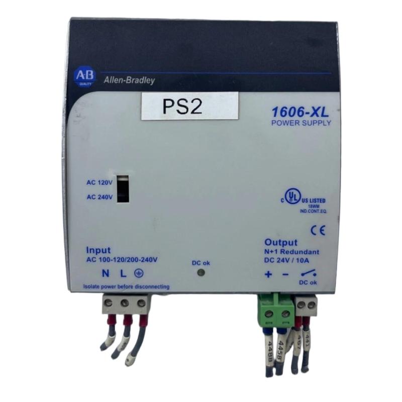
Table of Contents
- 1606-XL240DR Redundant Power Supply Overview
- Industrial Applications
- Installation Preparation
- DIN Rail Installation Procedure
- Power Wiring and Redundancy Connection
- System Power Configuration
- Startup Commissioning Process
- Installation Summary
1606-XL240DR Redundant Power Supply Overview
The Allen-Bradley 1606-XL240DR Redundant Power Supply Installation Guide provides detailed procedures for mounting, wiring, configuring, and commissioning reliable DC power systems for industrial automation applications.
The 1606-XL240DR is a redundant power supply module designed to provide stable DC power and improve system availability in critical industrial control environments.
The redundant power design allows automation systems to maintain continuous operation by improving power reliability and reducing the risk of unexpected shutdown caused by power supply problems.
Industrial Applications
The Allen-Bradley 1606-XL240DR redundant power supply is commonly installed in:
- PLC control cabinets
- Industrial automation systems
- Process control equipment
- Manufacturing production lines
- Safety-related control systems
- Communication and monitoring systems
Installation Preparation
Before installing the 1606-XL240DR module, engineers should prepare the following:
- Confirm AC input power requirements
- Verify DC load capacity
- Check cabinet installation space
- Prepare DIN rail mounting location
- Review electrical connection drawings
- Confirm grounding requirements
DIN Rail Installation Procedure
The 1606-XL240DR is designed for installation inside industrial control cabinets using DIN rail mounting.
- Disconnect incoming power supply
- Select suitable DIN rail position
- Install the power supply module
- Confirm secure mechanical mounting
- Check ventilation clearance
Proper mechanical installation improves heat dissipation and ensures long-term operation stability.
Power Wiring and Redundancy Connection
Correct wiring is essential for reliable redundant power operation.
- Connect AC input terminals correctly
- Connect protective grounding
- Connect 24VDC output terminals
- Verify positive and negative polarity
- Connect redundant power paths correctly
- Check all terminal tightening conditions
1606_XL240DR_INSTALL_CHECK

MODEL = 1606-XL240DR

CHECK_01 = AC_INPUT
CHECK_02 = DC_OUTPUT
CHECK_03 = REDUNDANCY_CONNECTION
CHECK_04 = GROUNDING
CHECK_05 = VOLTAGE_TEST
System Power Configuration
After completing wiring, engineers should verify the redundant power configuration.
- Confirm output voltage level
- Check connected load requirements
- Verify power distribution path
- Confirm backup power availability
- Check system status indicators
Startup Commissioning Process
The commissioning procedure includes:
- Inspect all wiring connections
- Apply input power
- Check power supply indicators
- Measure DC output voltage
- Verify connected equipment operation
- Test redundant operation function
- Record commissioning results
Installation Summary
The Allen-Bradley 1606-XL240DR Redundant Power Supply installation process requires correct DIN rail mounting, accurate power wiring, proper redundancy configuration, and complete commissioning testing. A professional installation ensures stable DC power delivery and improves reliability in industrial automation systems.