
NewsNEWCENTER
Featured products
Contact Us
Allen Bradley 1336-L7E Control Interface Board Troubleshooting Guide
2026-09-04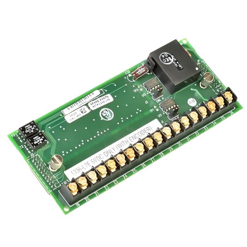
Table of Contents
- Allen Bradley 1336-L7E Fault Diagnosis Thinking Process
- Allen Bradley 1336-L7E Control Interface Board Fault Symptoms
- Allen Bradley 1336-L7E Troubleshooting: Board or External Circuit?
- Allen Bradley 1336-L7E Electrical Signal Analysis
- Allen Bradley 1336-L7E Connector and Wiring Fault Diagnosis
- Allen Bradley 1336-L7E Repair and Replacement Strategy
- Allen Bradley 1336-L7E Real Fault Diagnosis Case
- Allen Bradley 1336-L7E Troubleshooting FAQ
- Allen Bradley 1336-L7E Troubleshooting Technical Summary
Allen Bradley 1336-L7E Fault Diagnosis Thinking Process
Allen Bradley 1336-L7E Control Interface Board faults should be diagnosed by separating board-level problems from external control, wiring and drive-configuration problems. If a 1336 drive loses a command, produces an unexpected status condition or becomes intermittently unresponsive, replacing the board immediately can lead to unnecessary downtime.
A better Fault Diagnosis question is: What changed, and where does the expected signal disappear? This approach is especially useful when troubleshooting older installed 1336 drive systems.
Allen Bradley 1336-L7E Control Interface Board Fault Symptoms
Symptoms associated with the control interface can vary depending on the overall drive configuration. Common field observations include:
- Drive does not respond to an expected external command.
- Intermittent control response.
- Unexpected drive status.
- Control-related fault conditions.
- Communication or interface instability.
- Incorrect response to a reference signal.
- Faults appearing immediately after board replacement.
The final symptom alone is not enough to identify a defective Control Interface Board. Timing, signal measurements and configuration history are more useful diagnostic evidence.
Allen Bradley 1336-L7E Troubleshooting: Board or External Circuit?
The first troubleshooting decision should be to divide the system into functional sections.
External Control Wiring
          |
          v
Command / Reference Signal
          |
          v
1336-L7E Interface
          |
          v
Drive Control Electronics
          |
          v
Power Section
          |
          v
Motor
If the command signal is already missing before it reaches the control interface, replacing the board will not correct the problem. Conversely, if the expected signal reaches the interface correctly and the drive still fails to process it, the investigation should move toward the internal control architecture.
Allen Bradley 1336-L7E Electrical Signal Analysis
Use the electrical drawings for the specific drive installation to identify expected signal levels and measurement points. Do not assume that every terminal has the same reference or voltage.
- Measure the relevant control supply.
- Verify the external command signal.
- Check signal stability while the command changes.
- Verify continuity through associated wiring.
- Check reference potential and grounding.
- Compare measurements with known-good operating conditions.
Example Diagnostic Record

Control supply:     approximately 24 VDC
Command ON:         approximately 24 VDC
Command OFF:        approximately 0 VDC
Observed symptom:   intermittent command
Test condition:     machine stationary
Next check:         connector and cable continuity
The values above are an example diagnostic format, not universal terminal specifications for every 1336 installation. Actual measurements must be compared with the applicable drive drawings and System Configuration.
Allen Bradley 1336-L7E Connector and Wiring Fault Diagnosis
Connector problems are particularly important after maintenance because they can be introduced during board replacement.
- Inspect connector locking mechanisms.
- Look for bent or recessed contacts.
- Check for loose conductors.
- Inspect cable insulation.
- Check for contamination.
- Verify shielding and grounding arrangements.
- Compare every connector with the pre-maintenance record.
Intermittent faults require additional attention. A connection that passes a static continuity test can still fail under vibration or thermal movement.
Allen Bradley 1336-L7E Repair and Replacement Strategy
Repair should proceed from the simplest verifiable cause toward the more complex internal failure.
- Review the fault history and operating conditions.
- Verify the drive’s external control signals.
- Inspect connectors and wiring.
- Check the approved System Configuration.
- Compare measurements with expected values.
- Inspect the Control Interface Board for physical abnormalities.
- Test the drive under controlled conditions.
- Replace the board only when evidence supports a board-level fault.
When a replacement board is installed, repeat the complete Setup and Commissioning verification rather than assuming that the repair is complete.
Allen Bradley 1336-L7E Real Fault Diagnosis Case
A maintenance team working on a conveyor drive reported an intermittent start command after servicing the control electronics. The machine would start correctly several times and then fail to respond.
The initial diagnosis pointed toward the 1336-L7E because the problem appeared after control-board maintenance. However, the engineer first monitored the command circuit while repeatedly operating the external start control.
The expected control voltage was approximately 24 VDC when the command was active. During the failure, the command signal remained present at the originating control terminal but became unstable at the corresponding drive-side connection.
Inspection of the connector revealed that one contact was not making reliable electrical contact. Moving the cable slightly reproduced the fault, providing a strong correlation between the physical connection and the observed symptom.
After correcting the connection, the command remained stable during more than thirty repeated start/stop cycles. The Control Interface Board was retained in service.
This is a useful field Troubleshooting pattern: when a problem appears immediately after maintenance, investigate the work that was performed before assuming that the replacement component itself has failed.
Allen Bradley 1336-L7E Troubleshooting FAQ
What should be checked before replacing the 1336-L7E?
Check the relevant control power, external command signals, wiring, connectors, grounding and drive configuration first.
Why can an intermittent connector fault be difficult to find?
A connector may pass a stationary continuity test but lose reliable contact because of vibration, cable movement, contamination or mechanical damage.
Does a drive fault automatically mean the Control Interface Board has failed?
No. A drive fault can originate from external control circuits, configuration, communication paths, sensors, wiring or other internal assemblies.
What is the best approach after installing a replacement board?
Perform a complete Setup and Commissioning check, including connector verification, configuration review, control-signal testing and controlled drive operation.
Allen Bradley 1336-L7E Troubleshooting Technical Summary
Effective Allen Bradley 1336-L7E Control Interface Board Troubleshooting depends on separating symptoms from root causes. Engineers should trace the expected command and control signals, inspect connectors and wiring, verify the System Configuration and compare measured values with the approved electrical documentation before condemning the board. This Fault Diagnosis method reduces unnecessary replacements and provides a more reliable path to Repair when the 1336 drive develops intermittent or persistent control problems.