
NewsNEWCENTER
Featured products
Contact Us
Allen Bradley 1336-L7E Control Interface Board Installation Guide
2026-09-04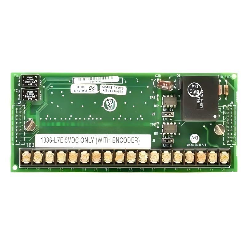
Table of Contents
- Allen Bradley 1336-L7E Control Interface Board Installation Overview
- Allen Bradley 1336-L7E Control Interface Board Function
- Allen Bradley 1336-L7E Installation Preparation
- Allen Bradley 1336-L7E Board Installation and Handling
- Allen Bradley 1336-L7E Electrical Connections
- Allen Bradley 1336-L7E Setup and Drive Configuration
- Allen Bradley 1336-L7E Commissioning and Validation
- Allen Bradley 1336-L7E Field Installation Experience
- Allen Bradley 1336-L7E Installation FAQ
- Allen Bradley 1336-L7E Installation Technical Summary
Allen Bradley 1336-L7E Control Interface Board Installation Overview
Allen Bradley 1336-L7E Control Interface Board installation should be treated as a drive-level integration task, not simply as a circuit board replacement. The correct approach is to identify the board’s position in the 1336 drive architecture, document existing connections, protect the electronics from electrostatic discharge, and verify the drive configuration after installation.
The 1336-L7E is associated with the control interface portion of an Allen Bradley 1336 drive system. During an Installation Guide procedure, technicians should pay particular attention to connector identification, cable routing, board seating, grounding and the relationship between the control electronics and the drive’s other assemblies.
A replacement board can be physically installed correctly and still produce commissioning problems if connectors are transferred incorrectly or the existing drive configuration is not checked before startup.
Allen Bradley 1336-L7E Control Interface Board Function
The control interface section of an industrial drive provides the electrical interface between control electronics and the drive’s internal circuitry. Depending on the specific 1336 drive configuration, related control functions can include command processing, status signals, external control interfaces and communication with other drive assemblies.
For this reason, the 1336-L7E should not be evaluated in isolation. A Fault Diagnosis performed after replacement must distinguish between a defective Control Interface Board and problems elsewhere in the drive.
- Control signal interface.
- Internal drive control communication.
- Interface between control electronics and associated assemblies.
- Support for the configured drive control architecture.
- Interaction with external command and status circuits.
Allen Bradley 1336-L7E Installation Preparation
Before removing an existing board, record the drive’s model information, parameter settings, connector positions and wiring arrangement. Photographs of the original assembly are particularly useful when several connectors have similar physical characteristics.
- Disconnect and isolate the drive according to site safety procedures.
- Allow the drive DC bus to discharge according to the manufacturer’s safety requirements.
- Verify the absence of hazardous voltage with an appropriate meter.
- Use suitable ESD protection when handling the Control Interface Board.
- Document connector locations before removal.
- Inspect the replacement board for visible mechanical damage.
Do not rely on memory when transferring wiring. A connector installed in the wrong position can create symptoms that look like a board failure during Commissioning.
Allen Bradley 1336-L7E Board Installation and Handling
Handle the Allen Bradley 1336-L7E by its edges whenever possible. Avoid touching exposed electronic components, connector contacts and circuit traces. ESD damage may not produce an immediate visible symptom, making preventive handling particularly important.
Before securing the board, inspect mounting points and connectors for contamination, bent contacts or mechanical damage. The board should sit correctly in its intended position without excessive force.
Never compensate for misalignment by forcing a connector. If the connector does not engage naturally, stop the installation and identify the cause.
Allen Bradley 1336-L7E Electrical Connections
Correct connector transfer is one of the most important parts of the Installation Guide. Use the original drive documentation and the identification markings on the actual assembly to verify every connection.
- Identify each connector before removal.
- Compare the old and replacement board layouts.
- Transfer one connection at a time.
- Check connector seating.
- Inspect surrounding wiring for damage.
- Verify grounding and shielding arrangements.
Control System
      |
      v
External Command / Status
      |
      v
1336 Drive Control Architecture
      |
      v
1336-L7E Control Interface Board
      |
      +---- Internal Drive Electronics
      |
      +---- Power / Switching Assemblies
Do not change external control wiring during the same maintenance activity unless the modification is part of the approved engineering work. Keeping the scope controlled makes later Troubleshooting much easier.
Allen Bradley 1336-L7E Setup and Drive Configuration
After mechanical installation and wiring verification, review the drive’s existing System Configuration before returning the machine to service.
- Confirm the intended command source.
- Verify reference and control signal configuration.
- Check applicable protection settings.
- Review stored drive parameters.
- Confirm communication-related settings where applicable.
- Compare the configuration with the machine’s electrical drawings.
If the original control board was replaced because of a fault, do not assume that replacing the hardware automatically resolves the underlying problem. Investigate the conditions that caused the original failure, including wiring, electrical stress and environmental conditions.
Allen Bradley 1336-L7E Commissioning and Validation
Commissioning should begin with the machine in a safe state. Verify the control interface before applying a normal production command.
- Complete a visual inspection.
- Verify all connectors.
- Restore the approved drive configuration.
- Apply power according to site procedures.
- Check drive status indications.
- Test the control command.
- Verify the reference signal.
- Perform a controlled motor test.
- Confirm normal operation under representative load.
During the first test, monitor for unexpected drive faults, unstable commands, incorrect direction, abnormal motor behavior and communication abnormalities. A controlled low-risk test is preferable to immediately placing the drive into automatic production.
Allen Bradley 1336-L7E Field Installation Experience
In one drive maintenance case, a replacement control interface assembly was installed after an older 1336 drive began producing intermittent control-related faults. The replacement board itself appeared correct, but the drive would not respond consistently to the machine’s external command.
The first assumption was that the replacement board was defective. Instead of replacing it again, the technician compared the connector arrangement with photographs taken before disassembly.
One control connection had not been fully seated after the board replacement. The electrical measurement at the affected control circuit changed between approximately 24 VDC and an unstable lower value as the connector was disturbed.
After the connector was correctly seated and the wiring was secured, the command signal remained stable at approximately 24 VDC and the drive responded normally during repeated start and stop tests.
The important lesson is that a post-installation fault does not automatically indicate a failed board. Connector seating, wiring continuity and configuration should be verified before another replacement is attempted.
Allen Bradley 1336-L7E Installation FAQ
Why is ESD protection important when installing the Allen Bradley 1336-L7E?
Electronic control boards can be damaged by electrostatic discharge even when no visible damage is present. Proper ESD handling reduces the risk of latent or immediate electronic failure.
Should connector positions be documented before board removal?
Yes. Photographs and written records provide a practical reference and reduce wiring errors during installation.
Should the drive configuration be checked after installation?
Yes. The Control Interface Board works within the complete drive control architecture, so the relevant System Configuration should be verified before Commissioning.
Can an incorrectly seated connector cause a board fault indication?
Yes. An incomplete electrical connection can create symptoms that resemble a defective Control Interface Board.
Allen Bradley 1336-L7E Installation Technical Summary
The Allen Bradley 1336-L7E Control Interface Board Installation Guide should combine safe drive isolation, ESD protection, careful connector identification, configuration verification and controlled Commissioning. The most reliable installation method is to document the original assembly before removal, reproduce the approved wiring accurately, and validate the complete drive system rather than evaluating the replacement board as an isolated component.