

ProductPRODUCT
Featured products

Contact Us
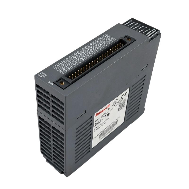
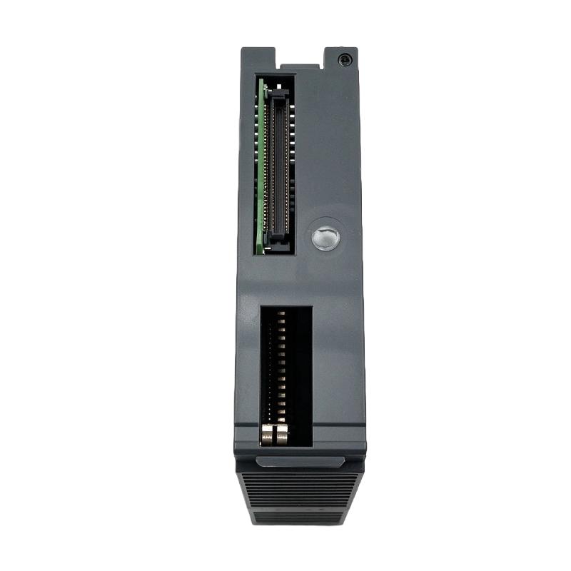
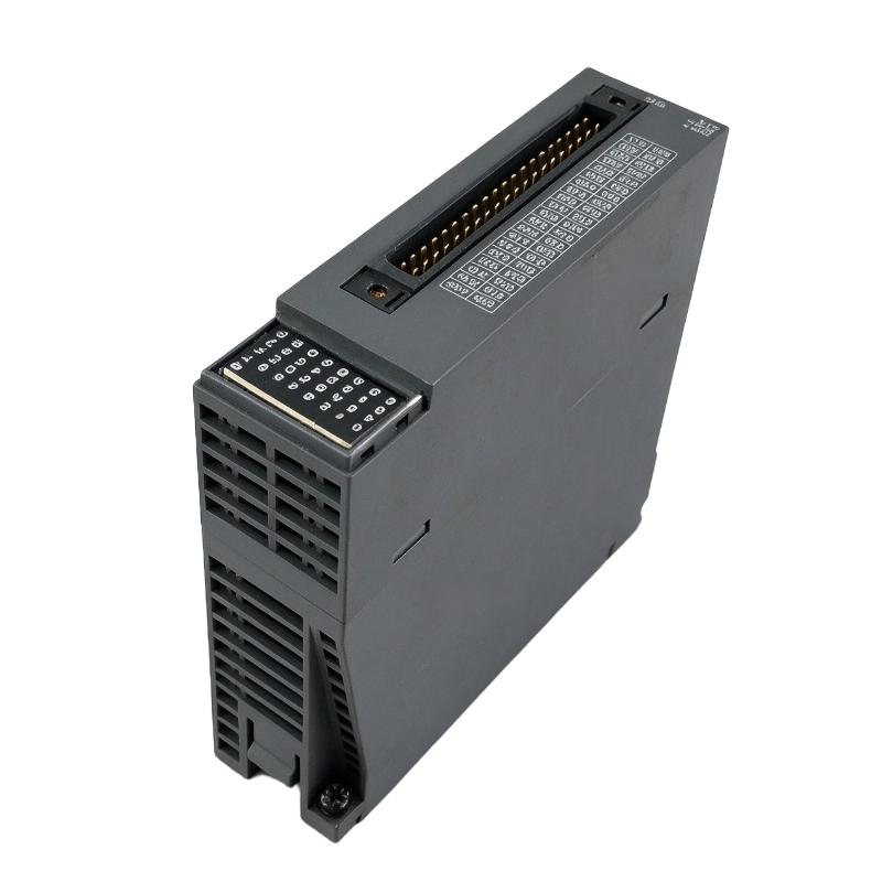
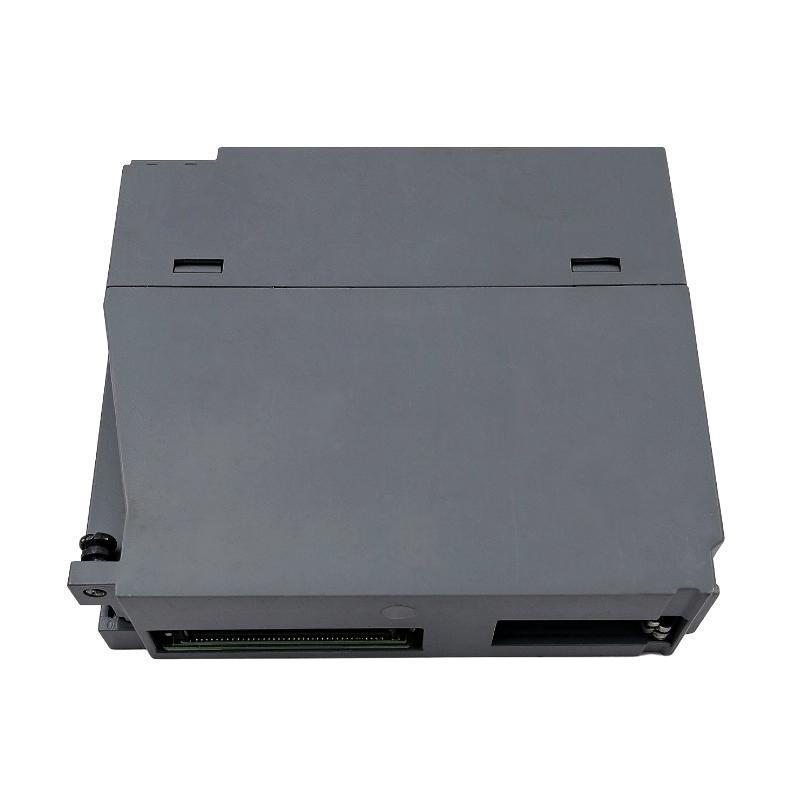
- Honeywell
- 2MLQ-TR1C
- Digital Output Module
- USA
- 114 × 48 × 127 mm
- 0.15 kg
- Xiamen, China
- New & In Stock
- T/T, PayPal, Western Union
- 1 Year
- 1-3 Working Days
- DHL, UPS, TNT, FedEx and EMS.
- 24-Hour Service
- COO
- 11
Our advantage

Global Logistics
We have a 10-year logistics and express cooperation agreement, so our products can be shipped to any place in the world.

Brand new and original
Our products are imported in bulk from the place of origin. Because of the cooperative relationship, our products are all original and 100% new.

24-hour service
We provide 7*24 hours service to our customers. We will be there whenever you need us.

Price advantage
All our products are priced very favorably because we have our own warehouse and supply.
| Company Information | |||
| [email protected] | |||
| Mobile | +8615980777398 | ||
| +8615980777398 | |||
| 15980777398 |
Product Overview
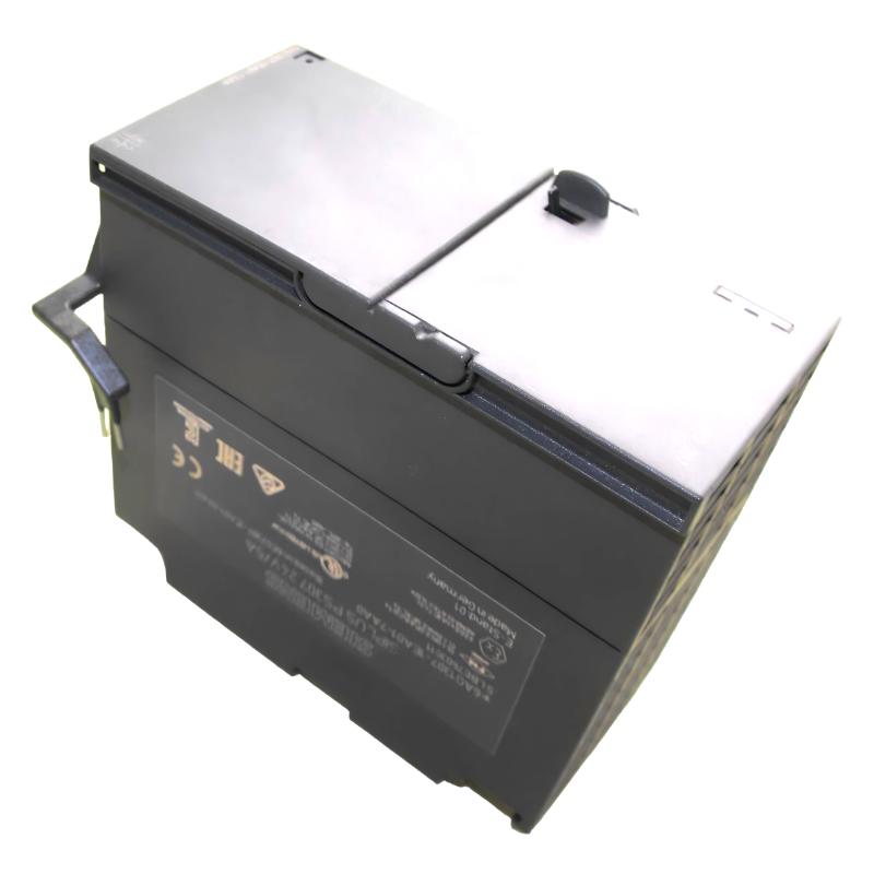
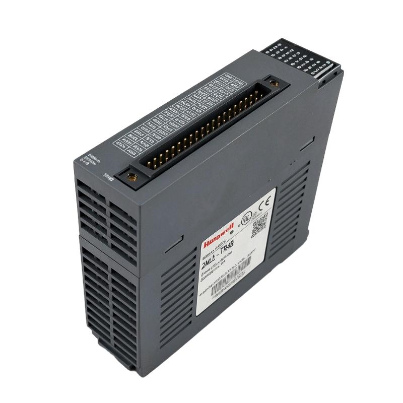
The Honeywell 2MLQ-TR1C is an 8-point isolated transistor output module belonging to the MasterLogic-200 PLC system. It uses a sinking output configuration and supports a maximum load current of 2 A per output point. Its electrical configuration distinguishes it from the standard high-density transistor output modules in the same series.
In practical machine control, not every application requires 32 or 64 output channels. Some equipment uses a smaller number of DC actuators or switching devices, but each circuit requires a higher current capacity. The TR1C addresses this type of application with eight individually controlled output points.
The module supports DC 12/24 V load circuits and uses relay isolation. Each output point has an individual COM connection, allowing the field wiring to be organized separately. This is particularly useful in machinery where different actuator circuits operate independently and require clear wiring identification during commissioning and maintenance.
Typical applications include pneumatic control panels, automated assembly equipment, packaging machinery, and industrial machines with multiple DC switching devices. The PLC CPU handles the sequence and interlock logic, while the TR1C executes the corresponding output commands.
When selecting this module, engineers should pay particular attention to its sinking output arrangement, individual channel current rating, and external load requirements. These characteristics are more important than simply comparing the number of output points with other MasterLogic-200 modules.
Technical Specifications
| Parameter | Specification |
|---|---|
| Manufacturer | Honeywell |
| Model | 2MLQ-TR1C |
| Product Type | 8-Point Isolated Transistor Output Module |
| Product Series | MasterLogic-200 |
| Output Type | Transistor Output, Sink Type |
| Output Points | 8 |
| Isolation Method | Relay Isolation |
| Rated Load Voltage | DC 12/24 V |
| Load Voltage Range | DC 10.2–26.4 V |
| Maximum Load Current | 2 A per Point |
| Off-State Leakage Current | 0.1 mA or less |
| Maximum ON-State Voltage Drop | DC 0.3 V or less |
| Surge Absorber | Zener Diode |
| OFF-to-ON Response Time | 3 ms or less |
| ON-to-OFF Response Time | 10 ms or less (rated resistive load) |
| Common Configuration | 1 Point / 1 COM |
| Current Consumption | 100 mA (all points ON) |
| Operation Indicator | Output ON LED |
| External Connection | 18-Point Terminal Block Connector |
| Dimensions | 114 × 48 × 127 mm |
| Weight | 0.15 kg |
Product Features
1. Eight Isolated Transistor Output Points
The TR1C provides eight independently controlled transistor output channels. Its isolated output arrangement is suitable for control panels where individual field circuits need separate switching connections.
2. 2 A Maximum Load Current per Point
Each output point supports a maximum load current of 2 A. This higher individual channel rating distinguishes the TR1C from the standard high-density transistor output modules in the MasterLogic-200 family.
3. Sinking Output Configuration
The module uses sinking transistor outputs. External DC loads must be connected with the correct supply polarity and current-return arrangement.
4. DC 12/24 V Load Compatibility
The rated load voltage is DC 12/24 V, with an operating range of DC 10.2–26.4 V. This supports common industrial DC control circuits.
5. Individual COM Connections
Each output point has its own COM connection. This arrangement allows the eight field circuits to be wired individually rather than sharing a single common connection.
6. Relay Isolation
Relay isolation is specified for the output module. This characteristic should be considered when planning the electrical interface between the PLC system and external equipment.
7. Zener Diode Surge Absorption
The output circuit includes a Zener diode surge absorber. The characteristics of connected inductive loads should still be evaluated when selecting external circuit protection.
8. Defined Switching Response
The OFF-to-ON response time is 3 ms or less, while the ON-to-OFF response time is 10 ms or less under rated resistive-load conditions.
9. LED Output Status Indication
The Output ON LED provides a visual indication of channel activity. Technicians can use this indication when checking output operation during commissioning and fault diagnosis.
10. 18-Point Terminal Block Connection
The module uses an 18-point terminal block connector for external wiring, providing the connection interface for its eight output circuits.
Working Principle
The 2MLQ-TR1C operates as the output switching stage of a MasterLogic-200 PLC system. It receives output commands from the CPU and switches the connected DC field circuits according to the PLC program.
When the CPU activates an output point, the corresponding transistor switching circuit changes to its conducting state. With the sinking configuration, the output provides a current path toward the DC negative return. The connected load operates when the external supply and wiring conditions are correct.
When the CPU removes the output command, the transistor circuit returns to its inactive state and interrupts the normal load current.
The individual COM arrangement allows each output point to have a separate common connection. This is useful when several field devices operate independently and their wiring needs to be clearly separated.
For example, consider an automated assembly machine with eight DC actuator circuits. The PLC receives position signals from sensors and determines when each actuator should operate. The TR1C switches the corresponding output channel, allowing the machine to execute its programmed sequence.
The module’s response characteristics also need to be considered when calculating switching intervals. The specified OFF-to-ON response is 3 ms or less, while the ON-to-OFF response is 10 ms or less under rated resistive-load conditions.
Typical Control Sequence:
- Field sensors transmit equipment status signals to the MasterLogic-200 CPU.
- The CPU evaluates the operating conditions and programmed interlocks.
- The CPU sends an output command to the assigned TR1C channel.
- The transistor output circuit switches to its active state.
- Current flows through the connected DC load.
- The actuator or switching device performs its assigned operation.
- When the programmed condition is satisfied, the CPU removes the output command.
Role in MasterLogic-200 Control Architecture
Within the MasterLogic-200 architecture, the 2MLQ-TR1C provides the digital output interface between PLC logic and external DC equipment.
The CPU executes the control program, processes input information, and determines the required output states. The TR1C handles the corresponding electrical switching operations. This division allows machine sequence logic to remain in the controller while individual field devices are operated through dedicated output channels.
The TR1C is particularly relevant when the application requires eight isolated sinking outputs with a maximum current rating of 2 A per point. It should not be treated as an equivalent replacement for the higher-density TR2A, TR4A, or TR8A modules, which have different channel counts and current ratings.
| Component | Product Type | Function |
|---|---|---|
| 2MLQ-TR1C | 8-Point Isolated Transistor Output Module | Individual DC output switching |
| 2MLQ-TR2A | 16-Point Transistor Output Module | Sinking output control |
| 2MLQ-TR4A | 32-Point Transistor Output Module | High-density sinking output control |
| 2MLQ-TR8A | 64-Point Transistor Output Module | High-density sinking output control |
| 2MLQ-TR2B | 16-Point Transistor Output Module | Sourcing output control |
| 2MLQ-TR4B | 32-Point Transistor Output Module | Sourcing output control |
| 2MLQ-TR8B | 64-Point Transistor Output Module | High-density sourcing output control |
| 2MLQ-RY1A | 8-Point Relay Output Module | Relay-based switching |
| 2MLQ-RY2A | 16-Point Relay Output Module | Multiple relay output circuits |
| 2MLQ-RY2B | 16-Point Relay Output Module | Relay switching with built-in varistor |
| 2MLQ-SS2A | 16-Point Triac Output Module | AC output switching |
| 2MLI-CPUH | High Performance CPU Module | PLC program execution |
| 2MLI-CPUS | Standard CPU Module | PLC control processing |
| 2MLI-D28B | 64-Point Digital Input Module | Field signal acquisition |
| 2MLI-D24B | 32-Point Digital Input Module | Digital input monitoring |
| 2MLP-DC42 | DC Power Supply Module | PLC system power |
| 2MLP-ACF1 | AC Power Supply Module | PLC system power |
| 2MLB-M06A | Main CPU Base | Main system module installation |
| 2MLB-E08A | Expansion I/O Base | I/O system expansion |
Industrial Applications
| Application | Typical Use |
|---|---|
| Packaging Machinery | Switching individual DC actuator and clamping circuits |
| Pneumatic Automation | Controlling compatible DC solenoid valve circuits |
| Automated Assembly Lines | Operating positioning and handling devices |
| Material Handling Equipment | Controlling selected DC switching devices |
| Machine Tool Systems | Operating auxiliary machine functions |
| Industrial Production Lines | Managing independent actuator operations |
| Process Equipment | Switching compatible DC control loads |
| Automated Handling Systems | Executing programmed equipment movement sequences |
Installation and Maintenance
- Verify Module Identification: Confirm that the installed module is 2MLQ-TR1C and distinguish it from other MasterLogic-200 transistor output variants.
- Check Output Configuration: Verify that the external control circuit is compatible with the sinking output arrangement.
- Confirm Load Voltage: Ensure that the connected equipment operates within the specified DC 10.2–26.4 V load voltage range.
- Observe Current Ratings: Keep each output channel within its maximum specified load current of 2 A.
- Inspect COM Connections: Check the individual common connection for each output point and confirm that the field wiring matches the circuit diagram.
- Check Terminal Connections: Inspect the 18-point terminal block connector for loose wires, damaged contacts, or incorrect terminal assignments.
- Verify Supply Polarity: Confirm positive and negative DC supply connections before energizing the external circuits.
- Evaluate Load Characteristics: Check the current requirements and switching characteristics of connected solenoid valves, actuators, and other DC devices.
- Review Switching Frequency: Consider the specified maximum switching frequency of 3,600 times per hour when evaluating repetitive switching applications.
- Monitor LED Indicators: Observe the Output ON LEDs during commissioning to compare actual channel activity with PLC commands.
- Investigate Output Faults: If a field device does not respond, inspect the PLC logic, external power supply, terminal wiring, and connected load.
- Maintain Wiring Records: Keep updated documentation identifying output addresses, COM connections, field devices, and associated control functions.
Compatible System Components
| Model | Product Description | Application |
|---|---|---|
| 2MLI-CPUH | MasterLogic-200 High Performance CPU Module | Main control processing |
| 2MLI-CPUS | MasterLogic-200 Standard CPU Module | Standard PLC processing |
| 2MLI-D21A | Digital Input Module | Digital signal acquisition |
| 2MLI-D24B | Digital Input Module | 32-point field signal monitoring |
| 2MLI-D28B | Digital Input Module | 64-point field signal monitoring |
| 2MLQ-TR2A | 16-Point Transistor Output Module | Additional sinking outputs |
| 2MLQ-TR4A | 32-Point Transistor Output Module | High-density sinking outputs |
| 2MLQ-TR8A | 64-Point Transistor Output Module | Large-channel-count sinking outputs |
| 2MLQ-RY1A | 8-Point Relay Output Module | Relay switching circuits |
| 2MLQ-RY2A | 16-Point Relay Output Module | Additional relay output channels |
| 2MLP-DC42 | DC Power Supply Module | DC system power |
| 2MLP-ACF1 | AC Power Supply Module | AC system power |
| 2MLB-M06A | Main CPU Base | Main PLC rack installation |
| 2MLB-E08A | Expansion I/O Base | Additional I/O installation |
Recommended Related Models
| Model | Product Description |
|---|---|
| 2MLQ-TR2A | MasterLogic-200 16-Point Transistor Output Module, Sink Type |
| 2MLQ-TR4A | MasterLogic-200 32-Point Transistor Output Module, Sink Type |
| 2MLQ-TR8A | MasterLogic-200 64-Point Transistor Output Module, Sink Type |
| 2MLQ-TR2B | MasterLogic-200 16-Point Transistor Output Module, Source Type |
| 2MLQ-RY1A | MasterLogic-200 8-Point Relay Output Module |
| 2MLQ-SS2A | MasterLogic-200 16-Point Triac Output Module |
Key Advantages
- Eight isolated transistor output points.
- Sinking output configuration for DC control circuits.
- Maximum load current of 2 A per output point.
- Supports DC 12/24 V rated load circuits.
- Individual common connection for each output point.
- Relay isolation arrangement.
- Integrated Zener diode surge absorber.
- OFF-to-ON response time of 3 ms or less.
- ON-to-OFF response time of 10 ms or less under rated resistive-load conditions.
- Maximum switching frequency of 3,600 times per hour.
- LED output status indication.
- 18-point terminal block connection.
- Integration with the MasterLogic-200 PLC architecture.
Technical FAQs
1. What makes the 2MLQ-TR1C different from the 2MLQ-TR2A?
The main difference is the output configuration and channel rating. The TR1C provides eight isolated sinking transistor outputs with a maximum current of 2 A per point. The TR2A provides 16 sinking transistor outputs rated at 0.5 A per point. The appropriate choice depends on the required channel count and individual load current.
2. Can the 2MLQ-TR1C control DC solenoid valves?
It can be used with compatible DC solenoid valve circuits when the load voltage, current, output polarity, and external wiring meet the module’s specifications. The actual coil current and switching requirements should be checked before connecting the valve.
3. Why does each output point have an individual COM connection?
The one-point-per-COM configuration allows each output circuit to have its own common connection. This simplifies the organization of independently controlled field circuits and is particularly useful in installations where different loads require separate wiring arrangements.
4. What response time should be considered when programming machine sequences?
The specified OFF-to-ON response time is 3 ms or less. The ON-to-OFF response time is 10 ms or less under rated resistive-load conditions. These values should be considered alongside PLC scan time and the actual response characteristics of connected field devices.