

ProductPRODUCT
Featured products
Contact Us
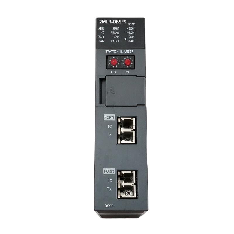
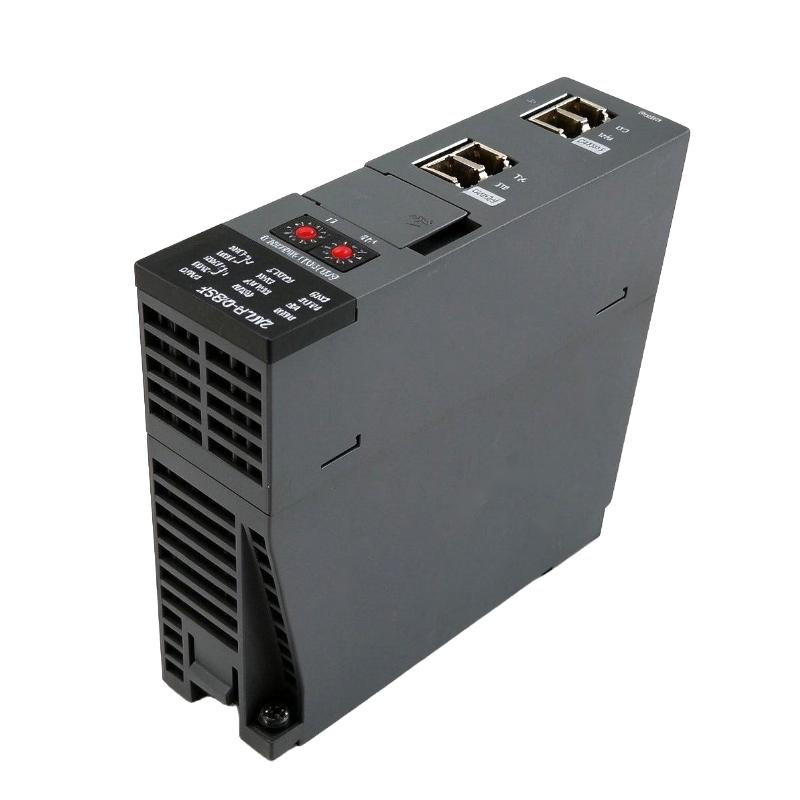
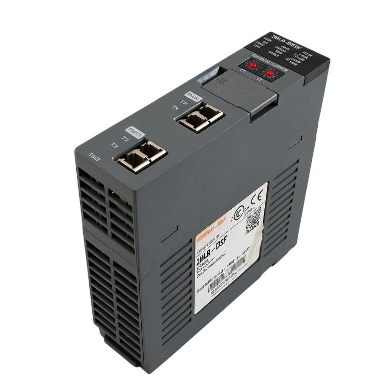
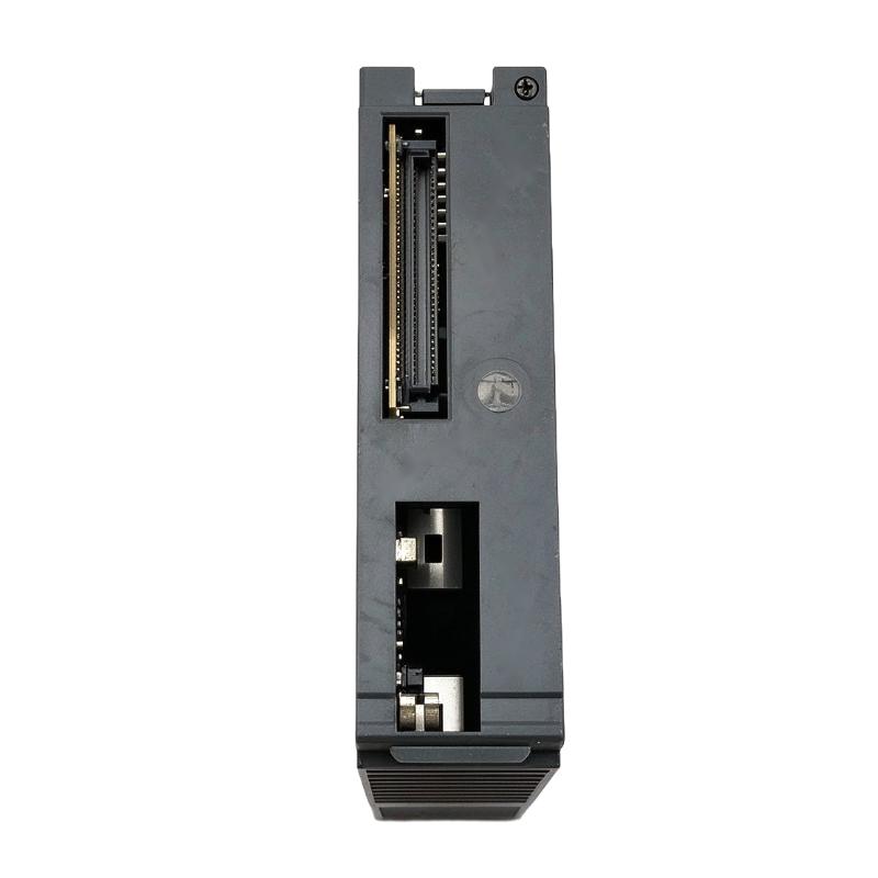
- Honeywell
- 2MLR-DBSFS
- Single-Mode Fiber Optic Expansion Driver Module
- USA
- 150 × 25 × 100 mm
- 0.12 kg
- Xiamen, China
- New & In Stock
- T/T, PayPal, Western Union
- 1 Year
- 1-3 Working Days
- DHL, UPS, TNT, FedEx and EMS.
- 24-Hour Service
- COO
- 9
Our advantage

Global Logistics
We have a 10-year logistics and express cooperation agreement, so our products can be shipped to any place in the world.

Brand new and original
Our products are imported in bulk from the place of origin. Because of the cooperative relationship, our products are all original and 100% new.

24-hour service
We provide 7*24 hours service to our customers. We will be there whenever you need us.

Price advantage
All our products are priced very favorably because we have our own warehouse and supply.
| Company Information | |||
| [email protected] | |||
| Mobile | +8615980777398 | ||
| +8615980777398 | |||
| 15980777398 |
Product Overview
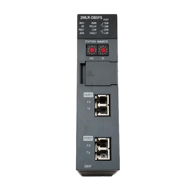
The Honeywell 2MLR-DBSFS is a single-mode fiber optic expansion driver module for the MasterLogic-200R PLC system. It serves as the communication interface between the main controller and remote I/O expansion bases, allowing the control system to distribute its I/O hardware across different locations without relying on conventional electrical communication links.
In a large industrial installation, the main PLC cabinet and remote I/O cabinets are not always located in the same equipment room. For example, a process plant may have its main controller in a centralized control cabinet while individual I/O stations are installed near pumps, compressors, production equipment, or field instrumentation. The 2MLR-DBSFS provides the optical communication interface needed for this type of distributed arrangement.
The single-mode fiber interface is particularly relevant when the communication route requires longer-distance transmission. Unlike conventional copper communication wiring, optical fiber does not use electrical signals to carry data between the connected expansion interfaces. This helps avoid communication problems associated with electromagnetic interference, electrical noise, and ground potential differences.
The module belongs to the MasterLogic-200R expansion driver family. Its role is different from that of a CPU or an I/O module: it handles communication between the controller architecture and the expansion I/O network rather than directly executing application logic or acquiring field signals.
For engineers maintaining MasterLogic-200R installations, the distinction between the single-mode DBSFS and the standard fiber-optic DBSF is important. Fiber type, optical interface compatibility, and the corresponding expansion network configuration should all be checked before selecting a replacement module.
Technical Specifications
| Parameter | Specification |
|---|---|
| Manufacturer | Honeywell |
| Model | 2MLR-DBSFS |
| Product Type | Single-Mode Fiber Optic Expansion Driver Module |
| Product Series | MasterLogic-200R |
| Module Function | Expansion Driver |
| Communication Media | Single-Mode Optical Fiber |
| Fiber Type | Single-Mode Fiber |
| Fiber Specification | 9/125 µm |
| Optical Interface | Fiber Optic |
| Connector Type | LC |
| Application | Remote I/O Expansion Communication |
| System Architecture | MasterLogic-200R |
| Station Number Range | 1–31 |
| Station Number 0 | Not Available |
| Loader Connection | Expansion Drive USB |
| Installation Position | CPU0 connector in expansion base |
| Dimensions | 150 × 25 × 100 mm |
| Weight | 0.12 kg |
Product Features
1. Single-Mode Fiber Optic Communication
The 2MLR-DBSFS uses single-mode optical fiber for communication between expansion interfaces. This configuration is relevant to installations requiring optical transmission over longer cable routes than conventional electrical expansion connections.
2. Remote I/O Expansion
The module allows the MasterLogic-200R architecture to extend its I/O arrangement beyond the main controller base. Remote expansion bases can be installed closer to field equipment, reducing the need to route every field signal back to a centralized cabinet.
3. Optical Signal Transmission
Data is transmitted through optical fiber rather than electrical conductors. This avoids direct electrical coupling between the connected expansion interfaces and helps reduce the effects of electromagnetic interference.
4. Single-Mode Fiber Compatibility
The single-mode configuration uses 9/125 µm optical fiber. It must be distinguished from the multimode fiber configuration associated with the standard 2MLR-DBSF model.
5. LC Optical Connector Interface
The LC connector arrangement provides the optical connection for the fiber communication link. Connector type and fiber specifications should be matched at both ends of the expansion network.
6. MasterLogic-200R System Integration
The module belongs to the MasterLogic-200R expansion driver family and works as part of the distributed I/O architecture. It is not intended to function as a standalone communication controller.
7. Station Address Configuration
The expansion network supports station numbers from 1 to 31. Station number 0 is unavailable, so address planning is necessary when multiple expansion bases are connected.
8. USB Loader Connection
The expansion driver architecture includes a USB loader connection for the relevant expansion drive interface. This is useful during system configuration and service procedures.
9. Dedicated Expansion Base Installation
The module is installed at the CPU0 connector position of the expansion base. Correct installation is necessary for the expansion driver to communicate with the associated I/O base.
10. Distributed Industrial Control
The optical expansion arrangement is suitable for installations where remote I/O cabinets are separated from the main PLC cabinet or exposed to electrically noisy operating conditions.
Working Principle
The 2MLR-DBSFS functions as an optical communication interface within the MasterLogic-200R expansion network. Its primary task is to transfer communication data between the main controller system and remote I/O expansion bases through single-mode fiber.
During normal operation, the main CPU processes the PLC program and exchanges I/O information with the expansion network. The expansion driver provides the communication path through which the remote I/O base participates in the overall control system.
For example, consider a production facility with several machine sections distributed across a large operating area. Instead of installing every I/O module inside the main controller cabinet, engineers can arrange remote I/O bases closer to the relevant equipment. The 2MLR-DBSFS establishes the optical communication interface required by the corresponding expansion arrangement.
When the PLC needs information from a remote I/O station, the communication system transfers the relevant data through the optical link. Output information is also exchanged so that the remote I/O arrangement can execute the control commands generated by the PLC program.
The use of single-mode fiber is especially relevant when the communication route is longer or when the installation requires separation from electrically noisy equipment. Because the communication medium is optical rather than electrical, the link is not subject to the same ground-loop and electromagnetic coupling problems as copper wiring.
Station addressing is another important part of operation. Each expansion station must use a valid address within the supported range. Incorrect or duplicated station assignments can prevent the controller from communicating with the intended remote I/O configuration.
Typical Communication Sequence:
- The main CPU executes the PLC application program.
- The controller exchanges I/O information with the expansion communication system.
- The 2MLR-DBSFS provides the optical communication interface.
- Data travels through the connected single-mode fiber link.
- The remote expansion driver receives the transmitted communication data.
- The remote I/O base exchanges the corresponding field input and output information.
- The controller continues processing the updated I/O data as part of the programmed control sequence.
Role in MasterLogic-200R Control Architecture
Within the MasterLogic-200R architecture, the 2MLR-DBSFS acts as the single-mode optical expansion driver. It provides the communication interface needed to connect remote I/O expansion hardware to the main controller arrangement.
The module should not be confused with the redundant CPU communication interface or the individual I/O modules. Its responsibility is specifically associated with expansion network communication.
The MasterLogic-200R platform includes several expansion driver configurations. These cover optical, electrical, and hybrid communication arrangements. Selecting the appropriate version depends on the communication medium and the expansion network design.
| Component | Product Type | Function |
|---|---|---|
| 2MLR-DBSFS | Single-Mode Fiber Optic Expansion Driver Module | Single-mode optical expansion communication |
| 2MLR-DBSF | Fiber Optic Expansion Driver Module | Multimode optical expansion communication |
| 2MLR-DBST | Twisted-Pair Expansion Driver Module | Electrical expansion communication |
| 2MLR-DBSH | Hybrid Expansion Driver Module | Combined optical and electrical communication |
| 2MLR-DBDF | Redundant Fiber Optic Expansion Driver Module | Redundant optical expansion communication |
| 2MLR-DBDT | Redundant Twisted-Pair Expansion Driver Module | Redundant electrical expansion communication |
| 2MLR-DBDH | Redundant Hybrid Expansion Driver Module | Redundant hybrid expansion communication |
| 2MLR-CPUH/T | Redundant CPU Module | Twisted-pair CPU communication |
| 2MLR-CPUH/F | Redundant CPU Module | Fiber-optic CPU communication |
| 2MLR-E12P | Expansion I/O Base | Remote I/O module installation |
| 2MLR-E12H | Redundant Expansion I/O Base | Redundant expansion configuration |
| 2MLR-AC22 | Redundant Power Supply Module | AC 220 V system power |
| 2MLR-AC12 | Redundant Power Supply Module | AC 110 V system power |
| 2MLR-DC42 | Redundant DC Power Supply Module | DC 24 V system power |
Industrial Applications
| Application | Typical Use |
|---|---|
| Oil and Gas Processing | Connecting remote I/O cabinets to centralized PLC control systems |
| Chemical Plants | Optical communication between separated process areas |
| Power Generation | Connecting distributed monitoring and control I/O stations |
| Water Treatment | Remote I/O communication across treatment and pumping facilities |
| Steel Manufacturing | Expansion communication in areas with significant electrical interference |
| Large Production Lines | Distributing I/O stations across different machine sections |
| Compressor Control Systems | Connecting remote equipment monitoring and control interfaces |
| Utility Automation | Optical expansion links between centralized and remote control cabinets |
Installation and Maintenance
- Verify Module Identification: Confirm that the installed module is 2MLR-DBSFS and distinguish it from the standard multimode 2MLR-DBSF and other expansion driver variants.
- Check Fiber Type: Use the specified single-mode optical fiber arrangement. Do not substitute multimode fiber without confirming compatibility with the installed module.
- Verify Connector Compatibility: Check that the optical connectors match the module interface and that the fiber connection is correctly seated.
- Inspect Optical Fiber Condition: Examine the cable for excessive bending, crushing, contamination, or other physical damage that could affect optical transmission.
- Check Installation Position: Install the expansion driver in the designated CPU0 connector position of the compatible expansion base.
- Verify Base Compatibility: Confirm that the expansion base and controller architecture support the selected DBSFS configuration.
- Configure Station Numbers: Assign valid expansion station numbers from 1 to 31. Station number 0 must not be used.
- Check Address Uniqueness: Review the complete expansion network configuration to prevent duplicate station assignments.
- Inspect Fiber Connections: Ensure that the optical link is connected correctly at both ends and that the cable routing follows the installation requirements.
- Review Communication Status: After startup, check the controller and expansion network status to identify communication faults or missing remote I/O stations.
- Check USB Loader Connection: When performing configuration or service procedures, verify the appropriate expansion drive USB connection and follow the applicable system instructions.
- Maintain Network Records: Document fiber routes, connector assignments, station numbers, expansion base locations, and module identification for future troubleshooting.
Compatible System Components
| Model | Product Description | Application |
|---|---|---|
| 2MLR-CPUH/F | MasterLogic-200R Redundant CPU Module, Fiber-Optic Interface | Fiber-based controller communication |
| 2MLR-CPUH/T | MasterLogic-200R Redundant CPU Module, Twisted-Pair Interface | Electrical controller communication |
| 2MLR-DBSF | Fiber Optic Expansion Driver Module | Multimode optical expansion |
| 2MLR-DBST | Twisted-Pair Expansion Driver Module | Electrical expansion communication |
| 2MLR-DBSH | Hybrid Expansion Driver Module | Optical and electrical expansion |
| 2MLR-DBDF | Redundant Fiber Optic Expansion Driver Module | Redundant optical expansion |
| 2MLR-E12P | MasterLogic-200R 12-Slot Expansion Base | Remote I/O installation |
| 2MLR-E12H | Redundant Expansion I/O Base | Redundant remote I/O arrangement |
| 2MLR-AC22 | Redundant AC Power Supply Module | AC 220 V power supply |
| 2MLR-AC12 | Redundant AC Power Supply Module | AC 110 V power supply |
| 2MLR-DC42 | Redundant DC Power Supply Module | DC 24 V power supply |
| 2MLC-F201 | Multimode Fiber-Optic Sync Cable | Fiber-optic system synchronization |
Recommended Related Models
| Model | Product Description |
|---|---|
| 2MLR-DBSF | MasterLogic-200R Fiber Optic Expansion Driver Module |
| 2MLR-DBST | MasterLogic-200R Twisted-Pair Expansion Driver Module |
| 2MLR-DBSH | MasterLogic-200R Hybrid Expansion Driver Module |
| 2MLR-DBDF | MasterLogic-200R Redundant Fiber Optic Expansion Driver Module |
| 2MLR-CPUH/F | MasterLogic-200R Redundant CPU Module, Fiber-Optic Interface |
| 2MLR-E12P | MasterLogic-200R 12-Slot Expansion Base |
Key Advantages
- Single-mode fiber-optic expansion communication.
- 9/125 µm single-mode fiber interface.
- LC optical connector configuration.
- Suitable for remote I/O expansion networks.
- Optical communication between separated PLC bases.
- Reduced susceptibility to electromagnetic interference.
- Electrical isolation between connected optical communication points.
- Station address configuration from 1 to 31.
- USB loader connection for expansion drive procedures.
- Installation through the CPU0 connector on the expansion base.
- Integration with the Honeywell MasterLogic-200R architecture.
- Suitable for distributed industrial automation installations.
Technical FAQs
1. What is the difference between the 2MLR-DBSFS and 2MLR-DBSF?
The main distinction is the optical fiber configuration. The 2MLR-DBSFS is identified as a single-mode fiber expansion driver, while the standard 2MLR-DBSF is specified for multimode fiber communication. The two should not be treated as interchangeable without checking the optical interfaces and network requirements.
2. Can the 2MLR-DBSFS communicate with a remote I/O base over single-mode fiber?
Yes. Its single-mode optical interface is intended for expansion communication over the corresponding single-mode fiber link. The remote expansion driver and optical connection must use a compatible configuration.
3. Where should the 2MLR-DBSFS be installed?
The expansion driver is installed in the CPU0 connector position of the compatible MasterLogic-200R expansion base. It is not a standalone PLC controller or an individual field I/O module.
4. Why must expansion station numbers be configured correctly?
The MasterLogic-200R expansion network uses station addressing to identify individual remote expansion bases. Valid station numbers range from 1 to 31, while station number 0 is unavailable. Incorrect or duplicated addresses can cause communication errors and prevent the intended expansion station from being recognized.