

ProductPRODUCT
Featured products
Contact Us
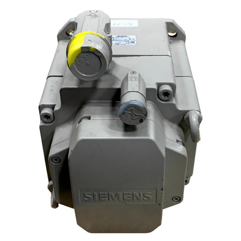
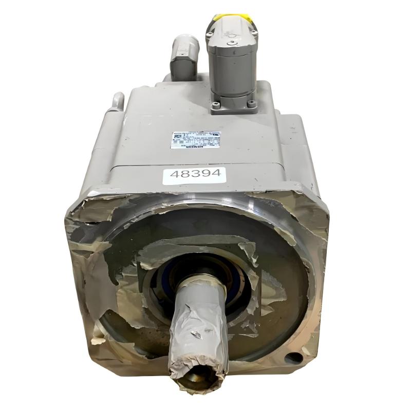
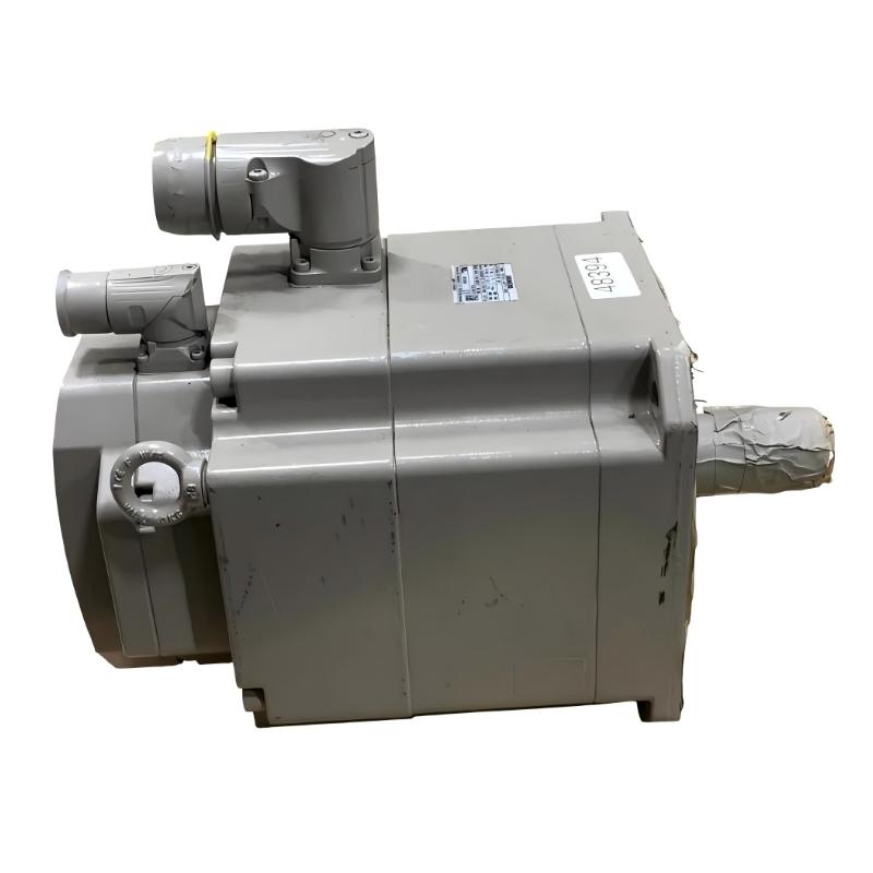
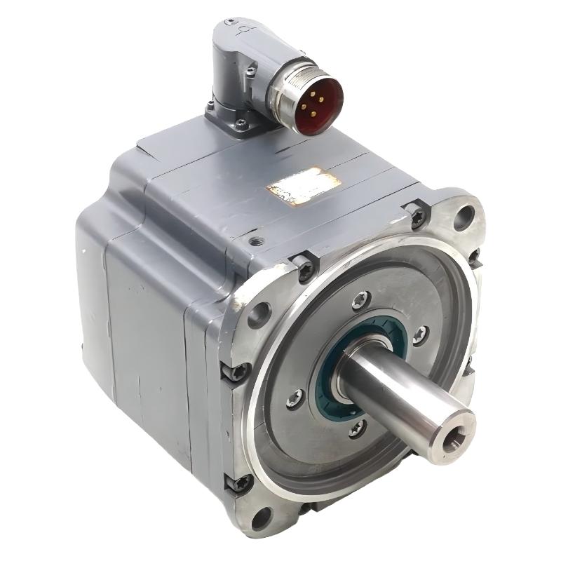
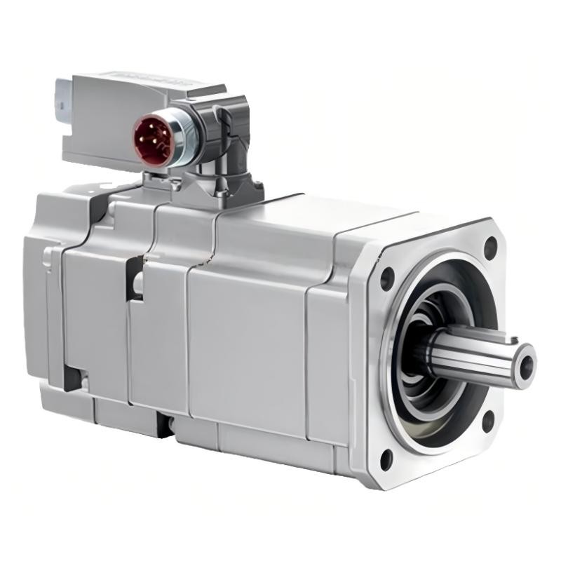
- Siemens
- 1FK7101-5AF71-1AH0
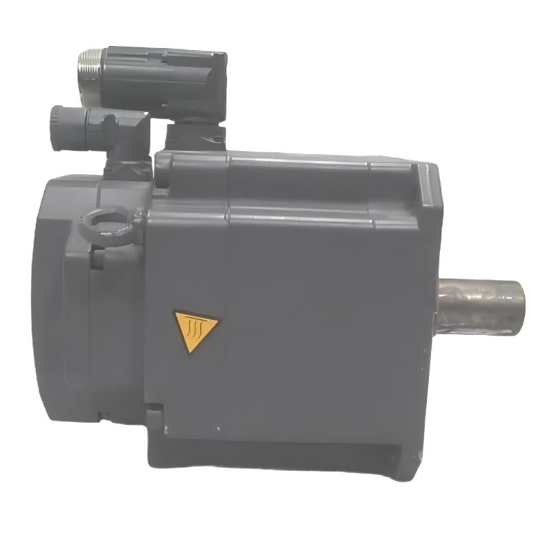
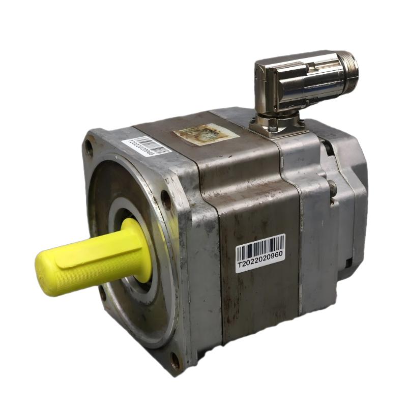
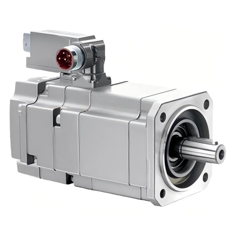
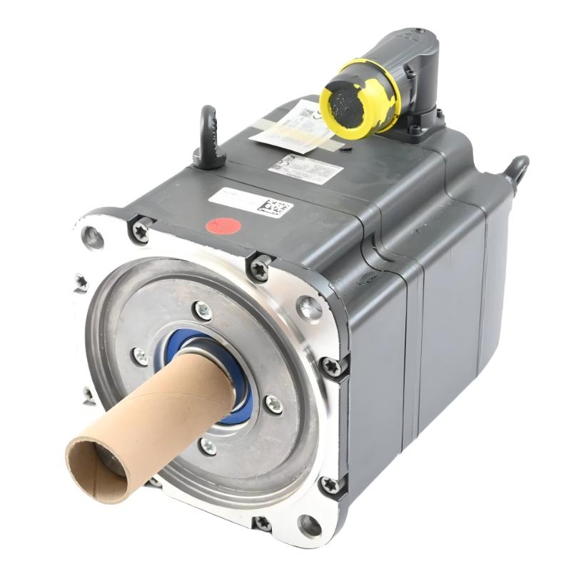
- SIMOTICS S Synchronous Motor
- Germany
- 300 mm x 200 mm x 150 mm
- 24kg
- Xiamen, China
- New & In Stock
- T/T, PayPal, Western Union
- 1 Year
- 1-3 Working Days
- DHL, UPS, TNT, FedEx and EMS.
- 24-Hour Service
- COO
- 8
Our advantage

Global Logistics
We have a 10-year logistics and express cooperation agreement, so our products can be shipped to any place in the world.

Brand new and original
Our products are imported in bulk from the place of origin. Because of the cooperative relationship, our products are all original and 100% new.

24-hour service
We provide 7*24 hours service to our customers. We will be there whenever you need us.

Price advantage
All our products are priced very favorably because we have our own warehouse and supply.
| Company Information | |||
| [email protected] | |||
| Mobile | +8615980777398 | ||
| +8615980777398 | |||
| 15980777398 |
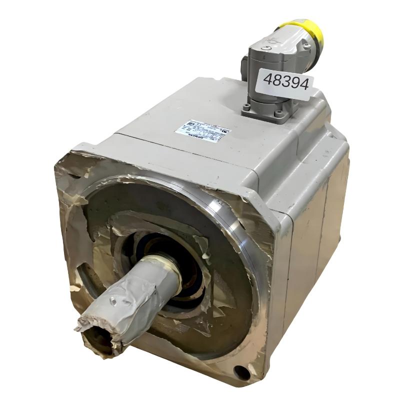
Siemens 1FK7101-5AF71-1AH0 Servo Motor — Technical Specifications, Product Introduction, Applications, Advantages and Related Models
1. Product Overview
The Siemens 1FK7101-5AF71-1AH0 is a model designation within the SIMOTICS S synchronous servo motor family, associated with the 1FK7 Compact series. This product family is designed for industrial motion-control applications that require controlled speed, dependable torque delivery, and repeatable positioning.
Servo motors in this class are commonly integrated into automated production machinery, machine tools, packaging systems, assembly equipment, and material-handling mechanisms. They operate as part of a complete drive system, working with a compatible servo drive and controller to produce controlled movement according to the machine’s programmed sequence.
The complete order number is important when identifying this motor. Variations in the final characters of a model designation can correspond to differences in feedback equipment, shaft arrangement, holding brake, or other configuration details. For that reason, the specifications of a closely related 1FK7 model should not automatically be applied to the 1FK7101-5AF71-1AH0 without checking the exact configuration.
This description separates the general characteristics of the 1FK7 Compact family from details that require confirmation for the precise order code. Exact electrical ratings, encoder type, brake configuration, dimensions, and weight should be established from the motor nameplate and its matching dimensional drawing before procurement or installation.
2. Detailed Technical Parameters
The 1FK7101-5AF71-1AH0 is specified as a naturally cooled synchronous servo motor with a rated speed of 3,000 rpm, an optimum operating power of approximately 4.85 kW, and a static torque rating of 27 Nm at a 100 K temperature rise. Unlike a configuration without a brake, this model includes a permanent-magnet holding brake.
| Parameter | Specification |
|---|---|
| Model | 1FK7101-5AF71-1AH0 |
| Brand | Siemens |
| Product family | SIMOTICS S |
| Series | 1FK7 Compact |
| Motor type | Synchronous servo motor |
| Motor technology | Permanent-magnet synchronous |
| Optimum operating power | 4.85 kW |
| Optimum operating speed | 3,000 rpm |
| Rated speed at 100 K temperature rise | 3,000 rpm |
| Rated torque at 100 K temperature rise | 15.5 Nm |
| Static torque at 60 K temperature rise | 22.4 Nm |
| Static torque at 100 K temperature rise | 27 Nm |
| Maximum torque | 80 Nm |
| Rated current | 11.8 A |
| Maximum current | 63 A |
| Stall current at 60 K temperature rise | Approximately 15.7 A |
| Stall current at 100 K temperature rise | Approximately 19.0 A |
| Number of poles | 8 |
| Maximum permissible mechanical speed | 5,000 rpm |
| Maximum inverter-related speed | 6,400 rpm, subject to specified conditions and mechanical limits |
| Cooling method | Natural cooling |
| Mounting arrangement | IM B5; IM V1 and IM V3 arrangements are specified |
| Encoder type | Incremental encoder |
| Encoder signal | SIN/COS, 1 Vpp |
| Encoder resolution | 2,048 pulses per revolution |
| Shaft design | Plain shaft |
| Shaft tolerance | N |
| Holding brake | Fitted; permanent-magnet brake |
| Protection rating | IP64 |
| Connector arrangement | Power and signal connectors, rotatable through 270° |
| Shaft height | 100 mm |
| Approximate motor net weight | 24.0 kg |
| Overall length | Must be confirmed from the exact dimensional drawing |
| Flange dimensions | Must be confirmed from the exact dimensional drawing |
| Shaft diameter and extension | Must be confirmed from the exact dimensional drawing |
| Drive compatibility | Requires a compatible servo drive and incremental encoder interface |
| Main application | Industrial automation, positioning and controlled motion |
2.1 Rated Power and Torque
The motor’s optimum operating point is approximately 4.85 kW at 3,000 rpm. Its rated torque is approximately 15.5 Nm at a 100 K temperature rise, while the specified static torque at the same temperature-rise condition is 27 Nm.
These values describe different operating conditions. Rated torque is relevant to normal operating performance, while static torque describes torque capability under the stated thermal condition at standstill or very low speed. The static rating should not automatically be treated as the continuous torque available at every speed.
The maximum torque of 80 Nm is a peak rating. Whether this torque can be used, and for how long, depends on the servo drive, current limits, motor temperature, and duty cycle. Applications with frequent acceleration, rapid reversal, or heavy intermittent loads should be assessed using a complete torque-speed and thermal calculation.
2.2 Speed and Dynamic Performance
A rated speed of 3,000 rpm makes the motor suitable for many industrial positioning and rotary-drive applications. The specified maximum permissible mechanical speed is 5,000 rpm.
A higher inverter-related speed figure does not mean that the motor can be operated beyond its mechanical limit in every installation. The actual permitted operating speed must be determined from the motor’s mechanical limits, the drive configuration, and the characteristics of the driven equipment.
The motor’s performance also depends on the load inertia and the required acceleration. A machine with a heavy rotating assembly may require more torque during acceleration than during steady-state operation. Correct selection therefore involves checking both continuous operating requirements and short-duration peaks.
2.3 Encoder and Feedback System
The motor uses an incremental SIN/COS encoder with a 1 Vpp signal and a resolution of 2,048 pulses per revolution. This encoder provides feedback for speed regulation and position control.
When the servo drive receives and processes the feedback correctly, it can adjust the motor’s operation to follow commanded motion. This is important in machines that require repeatable indexing, synchronized movement, or controlled stopping.
The encoder interface must match the selected drive. A motor with the correct rated power but an incompatible feedback interface may not operate correctly without an appropriate drive configuration or hardware arrangement.
2.4 Holding Brake
A major feature of the 1FK7101-5AF71-1AH0 is its fitted permanent-magnet holding brake. This distinguishes it from otherwise related configurations supplied without a brake.
A holding brake can help keep the motor shaft stationary when the motor is not producing driving torque. It is useful in applications where unwanted movement must be limited during a stop or while the drive is disabled.
The holding brake should not be treated as a substitute for correct mechanical support or as a complete safety braking system without an application-specific assessment. For vertical axes, gravity-loaded mechanisms, and personnel-protection applications, the brake’s specified holding torque, switching behavior, control circuit, and safety requirements must be checked.
2.5 Cooling and Protection
The motor uses natural cooling, with heat dissipated through the housing and surrounding air. Adequate ventilation is important, particularly when the motor is installed in an enclosed machine or close to other heat-generating components.
Its IP64 protection rating provides protection against dust ingress and splashing water under the conditions covered by the rating. It does not mean that the motor can be immersed in water or exposed to high-pressure cleaning.
The environmental suitability of the complete installation should also take account of the connectors, cable entries, contamination, ambient temperature, and available airflow.
2.6 Dimensions and Weight
The motor has a 100 mm shaft height and an approximate net weight of 24.0 kg for this brake-equipped configuration.
| Mechanical parameter | Specification |
|---|---|
| Shaft height | 100 mm |
| Mounting style | Flange-mounted |
| Listed mounting arrangements | IM B5, IM V1, IM V3 |
| Shaft design | Plain shaft |
| Shaft tolerance | N |
| Brake | Fitted |
| Approximate net weight | 24.0 kg |
| Overall motor length | Confirm from the exact dimensional drawing |
| Flange outside dimensions | Confirm from the exact dimensional drawing |
| Mounting-hole positions | Confirm from the exact dimensional drawing |
| Shaft diameter | Confirm from the exact dimensional drawing |
| Shaft extension | Confirm from the exact dimensional drawing |
| Connector clearance | Check against the installed connector orientation |
The shaft height is not the same as the motor’s total height, length, or flange size. For replacement projects, the overall dimensions and mounting details must be checked against the exact drawing rather than estimated from the model designation.
The brake adds weight compared with a similar configuration without a holding brake. For that reason, the approximate 24.0 kg figure is more appropriate for preliminary handling and mounting calculations than the weight of a brake-free variant.
3. Product Introduction
3.1 A Servo Motor for Industrial Motion Control
The Siemens 1FK7101-5AF71-1AH0 is designed for industrial machinery where motor movement must be controlled in accordance with a programmed sequence. Typical requirements include repeatable positioning, regulated rotational speed, controlled acceleration, and predictable stopping behavior.
A servo motor does not operate in isolation. It forms part of a drive system that includes a servo drive, controller, feedback connection, power cabling, and a mechanical transmission or driven load. The controller issues commands, the drive regulates motor current and movement, and the encoder supplies feedback.
When these components are selected and configured correctly, the system can support consistent movement across repeated production cycles. This is useful in automated equipment where movement accuracy and timing affect the quality or throughput of the process.
3.2 Mechanical Design and Installation Flexibility
The 1FK7 Compact design is intended for integration into industrial machinery. The flange-mounted arrangement provides a defined interface for attaching the motor to a machine housing, mounting plate, or mechanical assembly.
The plain shaft is intended to connect to a compatible coupling or transmission. Correct shaft alignment is essential. Misalignment can increase bearing loads, generate vibration, and reduce the service life of the motor and the driven mechanism.
The power and signal connectors can be rotated through 270 degrees. This provides additional flexibility when routing cables around machine frames, protective covers, and neighboring equipment. It can be particularly useful when the available installation space is limited.
3.3 The Importance of the Holding Brake
The fitted permanent-magnet holding brake makes this configuration relevant to applications where the shaft may need to remain stationary when the drive is not actively controlling the motor.
Examples include certain vertical positioning axes, lifting-related mechanisms, and machine assemblies that must retain their position during a controlled stop. The actual suitability depends on the load, brake rating, operating frequency, and required safety performance.
A holding brake is not intended to replace proper load-support design. Where gravity or stored mechanical energy could create a hazard, the complete system must be assessed for the required stopping and load-retention behavior.
3.4 Encoder-Based Position and Speed Control
The incremental encoder supplies motion feedback to the servo drive. This feedback can be used to regulate motor speed and track position changes during operation.
The achieved positioning accuracy depends on the complete machine. Mechanical backlash, coupling stiffness, transmission ratio, load inertia, controller response, and drive tuning all affect the result. The motor’s encoder specification is an important part of the system, but it does not by itself guarantee a particular machine-level positioning accuracy.
For replacement applications, the encoder signal type and resolution should be checked carefully. The drive must support the motor’s incremental SIN/COS, 1 Vpp feedback arrangement.
4. Product Applications
4.1 CNC Machine Tools
The motor may be considered for selected feed mechanisms, positioning axes, tool-changing assemblies, and auxiliary motion systems in CNC machinery.
These applications often require controlled acceleration and deceleration, stable rotational performance, and repeatable positioning. The motor and drive should be selected according to the required axis speed, load inertia, transmission ratio, and operating torque.
Where a machine uses a vertical axis or a mechanism that could move when the drive is disabled, the fitted holding brake may be relevant. The brake must still be checked against the load and the machine’s stopping requirements.
4.2 Packaging and Filling Machinery
Packaging machinery frequently combines product feeding, indexing, sealing, cutting, and transfer. Servo motors can control rollers, feeders, positioning assemblies, and other moving parts in accordance with the production sequence.
The 1FK7101-5AF71-1AH0 may be suitable for an axis that requires repeatable motion and a holding brake, provided that its rated torque, peak torque, and speed range match the application.
High-cycle packaging equipment should be evaluated for thermal loading. Frequent starts, stops, and reversals can create significant torque demand even when the average speed is relatively low.
4.3 Automated Assembly Equipment
Automated assembly systems use controlled movement to position, transfer, align, and insert components. Servo-driven mechanisms can help coordinate these operations and maintain repeatable cycle timing.
Potential applications include indexing tables, transfer slides, component-positioning units, and other automated machine axes.
The holding brake may be useful where a stationary position must be maintained during particular operating states. However, the required holding torque and the consequences of power loss must be evaluated as part of the complete machine design.
4.4 Material Handling and Positioning Systems
Material-handling systems may use servo motors to move products between workstations, control transfer mechanisms, or position equipment at defined points.
The motor’s feedback-based control can support programmed movement and coordinated operation with other axes. The brake-equipped configuration may also be relevant where the mechanism needs to remain stationary while the drive is not actively producing torque.
For lifting or gravity-loaded applications, confirm the brake rating, braking duty, external load-support requirements, and safety architecture before choosing this model.
4.5 Printing, Labeling and Converting Machinery
Printing and converting systems often require coordinated rotation, timed feeding, controlled cutting, and synchronized transfer. Servo motors can regulate the movement of rollers, feeding mechanisms, and auxiliary positioning axes.
The 1FK7101-5AF71-1AH0 may be considered where its torque and speed characteristics match the machine’s operating profile. The drive configuration should also support the encoder interface and the required control response.
The motor should be sized using the real operating cycle, including acceleration, deceleration, process load, and thermal demand.
4.6 Special-Purpose Machinery
Custom industrial machinery may combine several operations within a limited installation space. A flange-mounted servo motor can provide controlled motion for rotary mechanisms, indexing units, transfer systems, and programmed positioning assemblies.
The brake-equipped configuration can be relevant when the design requires the motor shaft to remain stationary under defined conditions. Nevertheless, the correct motor choice depends on the actual mechanical load, motion profile, installation dimensions, and control requirements.
5. Product Advantages
5.1 Integrated Holding Brake
The permanent-magnet holding brake is one of the main distinguishing features of the 1FK7101-5AF71-1AH0. It provides a means of holding the motor shaft when the drive is not actively producing torque, subject to the brake’s rated capabilities and operating conditions.
This can simplify the design of certain machine axes by providing a motor-mounted holding function. It is particularly relevant when evaluating vertical positioning systems and mechanisms that need to retain position during a stop.
The brake must be correctly controlled and sized. It should not be assumed to provide emergency stopping or personnel protection unless the complete system has been designed and validated for that purpose.
5.2 Feedback-Based Motion Control
The incremental SIN/COS encoder supports closed-loop speed and position regulation when used with a compatible servo drive.
This can help the machine execute repeated movements, controlled speed changes, and synchronized production sequences. Actual motion performance depends on the complete control system and mechanical assembly.
5.3 Useful Torque Capability
The motor’s rated torque is approximately 15.5 Nm, while its static torque rating at a 100 K temperature rise is 27 Nm. Its maximum torque rating provides a reference for short-duration demands, subject to the drive and thermal limits.
This performance range may suit machinery that requires controlled movement with intermittent acceleration or changing load conditions. The final selection should be based on continuous torque, peak torque, operating speed, and duty cycle rather than the maximum torque figure alone.
5.4 Flexible Connector Orientation
The power and signal connectors can be rotated through 270 degrees. This can simplify cable routing in compact installations and reduce interference with nearby mechanical structures.
The installer should still maintain appropriate cable clearance, bend radius, shielding, and protection against moving components.
5.5 Natural Cooling
Natural cooling avoids the need for a dedicated liquid-cooling circuit. In an appropriate operating environment, this can simplify machine integration and reduce the number of auxiliary cooling components.
Adequate airflow remains necessary. The motor’s usable continuous performance depends on ambient temperature, mounting conditions, load profile, and heat dissipation.
5.6 Industrial Protection
The IP64 rating provides protection against dust ingress and splashing water within the limits of the rating. This can be suitable for many indoor industrial applications.
The motor should not be assumed suitable for immersion, high-pressure washing, or aggressive chemical environments without a separate assessment of the complete installation.
5.7 Established Industrial Motor Format
The 1FK7 Compact design provides a defined motor format for integration into industrial motion-control systems. This can help when designing equipment around a known frame class and flange-mounted installation.
For replacement work, however, the full order code and dimensional drawing must be checked. A similar frame size does not guarantee that the shaft, brake, encoder, or connector arrangement will be interchangeable.
6. Brand and Product Series
| Item | Description |
|---|---|
| Brand | Siemens |
| Product family | SIMOTICS S |
| Product series | 1FK7 Compact |
| Motor type | Synchronous servo motor |
| Motor technology | Permanent-magnet synchronous |
| Cooling arrangement | Natural cooling |
| Mounting style | Flange-mounted |
| Feedback configuration | Incremental SIN/COS encoder, 1 Vpp |
| Encoder resolution | 2,048 pulses per revolution |
| Shaft arrangement | Plain shaft |
| Holding brake | Permanent-magnet brake fitted |
| Protection rating | IP64 |
| Main purpose | Industrial speed, torque, and position control |
The SIMOTICS S family is used for motion-control applications, while the 1FK7 Compact series provides synchronous servo motors for a range of industrial machinery.
The exact order number identifies the specific motor configuration. In the 1FK7 family, small differences in the suffix may indicate different encoder types, brake arrangements, shaft details, or protection ratings. Those differences can affect electrical compatibility, mechanical installation, and commissioning.
7. Five Related Models in the Same Series
The following models are useful for comparing brake arrangements, encoder configurations, and protection options within the 1FK7 Compact family. The complete suffix matters, so these models should not be treated as interchangeable without checking the exact specifications.
| Model | Main technical parameters | Dimensions and weight | Main features and differences |
|---|---|---|---|
| 1FK7101-5AF71-1AG0 | 4.85 kW; 3,000 rpm; 15.5 Nm rated torque; 27 Nm static torque at 100 K; incremental SIN/COS encoder, 1 Vpp, 2,048 pulses/rev; natural cooling; IP64 | Shaft height: 100 mm; overall dimensions: confirm drawing; weight: approximately 21 kg | Related configuration without a holding brake. Suitable for comparison where the machine does not require a motor-mounted holding brake. |
| 1FK7101-5AF71-1AB0 | 4.85 kW; 3,000 rpm; 15.5 Nm rated torque; 27 Nm static torque at 100 K; incremental SIN/COS encoder; natural cooling; IP64 | Shaft height: 100 mm; overall dimensions: confirm drawing; weight: approximately 24 kg | Includes a holding brake and a shaft with fitted key. The shaft arrangement differs from the plain-shaft configuration. |
| 1FK7101-5AF71-1AH0 | 4.85 kW; 3,000 rpm; 15.5 Nm rated torque; 27 Nm static torque at 100 K; incremental SIN/COS encoder, 1 Vpp, 2,048 pulses/rev; natural cooling; IP64 | Shaft height: 100 mm; overall dimensions: confirm drawing; weight: approximately 24 kg | Target model. Plain shaft, tolerance N, incremental encoder, and permanent-magnet holding brake. |
| 1FK7101-5AF71-1EH0 | Approximately 4.85 kW base operating point; 3,000 rpm; 15.5 Nm rated torque reference; absolute EnDat encoder, 2,048 pulses/rev; natural cooling; IP64; performance reduction associated with the absolute encoder | Shaft height: 100 mm; overall dimensions: confirm drawing; weight: approximately 24 kg | Absolute encoder and holding brake. Confirm the exact encoder specification and any performance reduction before selecting it as a substitute. |
| 1FK7101-5AF71-1UH0 | 3,000 rpm; approximately 4.85 kW base operating point; related 1FK7101 torque class; resolver feedback with DRIVE-CLiQ interface; natural cooling; IP64; holding brake | Shaft height: 100 mm; overall dimensions: confirm drawing; weight: approximately 24 kg | Resolver-based feedback and a holding brake. Drive compatibility must be checked carefully because the feedback arrangement differs from the target model. |
Comparison and Selection Guidance
1FK7101-5AF71-1AG0 is a useful comparison if the application does not require a built-in brake. Its overall electrical and mechanical configuration must still be checked against the target motor.
1FK7101-5AF71-1AB0 is worth considering where a brake is needed but the machine uses a keyed shaft. Its shaft interface differs from the plain shaft of the 1FK7101-5AF71-1AH0, so the coupling and transmission must be checked.
1FK7101-5AF71-1EH0 is relevant where absolute feedback is required. The encoder interface and any associated performance reduction should be considered before changing from the incremental encoder arrangement.
1FK7101-5AF71-1UH0 provides another feedback option through its resolver-based configuration. It is only suitable when the selected drive supports the required interface.
For all five models, the stated shaft height is a frame reference rather than a complete dimensional specification. Overall length, flange geometry, shaft diameter, and connector clearance should be verified from the exact drawing before purchasing a replacement.
8. Five Other Siemens Servo Motor Models for Comparison
The following table provides additional models that can be considered when evaluating servo motor options for industrial automation. They cover different frame classes and product configurations. They are comparison candidates rather than guaranteed direct replacements for the 1FK7101-5AF71-1AH0.
| Model | Product series / type | Technical parameters | Dimensions and weight | Typical application |
|---|---|---|---|---|
| 1FK7101-5AF71-1AG5 | SIMOTICS S, 1FK7 Compact | Approximately 4.85 kW; 3,000 rpm; 15.5 Nm rated torque; 27 Nm static torque at 100 K; incremental encoder, 2,048 pulses/rev; natural cooling; IP65; no holding brake | Shaft height: 100 mm; overall dimensions: confirm drawing; weight: approximately 20.87 kg | Related 100 mm frame motor with a higher stated protection rating. Check brake and shaft configuration before replacement. |
| 1FK7083-5AF71-1AG0 | SIMOTICS S, 1FK7 Compact | Synchronous servo motor; exact power, torque, current, and feedback ratings depend on the full configuration | 80 mm shaft-height class as a preliminary reference; overall dimensions and weight require confirmation | Compact positioning axes and machinery where a smaller frame can meet the required torque and acceleration. |
| 1FK7063-5AF71-1AG0 | SIMOTICS S, 1FK7 Compact | Synchronous servo motor; exact rated power, torque, speed, and encoder specifications must be confirmed | Smaller frame class; exact shaft height, overall dimensions, and weight require confirmation | Smaller automated mechanisms and positioning axes with appropriately sized loads. |
| 1FK7042-5AF71 | SIMOTICS S, 1FK7 Compact | Synchronous servo motor; electrical ratings and feedback configuration depend on the complete order code | Smaller frame class; exact dimensions and kg weight require confirmation | Compact automation equipment and lighter-duty positioning applications, subject to load calculations. |
| 1FT7105 | SIMOTICS S, 1FT family | Synchronous servo motor family; exact power, torque, speed, encoder, and brake specifications depend on the complete variant | Exact frame dimensions, overall length, and weight must be confirmed from the selected model’s drawing | An alternative motor family to evaluate for industrial motion-control systems with different mechanical or performance requirements. |
How to Evaluate These Alternatives
The 1FK7101-5AF71-1AG5 is a close frame-class comparison, particularly where IP65 protection is required. However, it does not have the same brake configuration as the target model, so it should not be assumed to provide the same load-holding function.
The 1FK7083 and 1FK7063 are smaller-frame candidates. A smaller motor may reduce installation space and mass, but it must still meet the required continuous torque, peak torque, speed, and acceleration.
The 1FK7042 is another smaller-frame option for applications with lower motion demands. It should only be considered after calculating the actual load and verifying the drive compatibility.
The 1FT7105 provides a broader comparison outside the 1FK7 Compact series. Its full technical data and mechanical interfaces must be assessed independently rather than inferred from the 1FK7101 model.
For every alternative, verify the complete order number, rated torque, maximum torque, encoder interface, brake arrangement, shaft design, mounting dimensions, and net weight before making a final selection.
9. Installation and Commissioning
9.1 Mechanical Installation
Before installation, inspect the motor flange, shaft, coupling, and mounting surface. The mounting interface should be clean, undamaged, and properly aligned.
The plain shaft must be connected using a compatible coupling or transmission. Incorrect alignment can increase vibration and bearing loads, resulting in premature wear or inconsistent positioning.
The approximate motor weight of 24 kg should be considered when planning handling and mounting arrangements. The mounting structure must also withstand the forces produced during acceleration and deceleration.
9.2 Electrical Connections
The servo drive must support the motor’s electrical characteristics and incremental SIN/COS encoder interface. Before energizing the system, check the connector pin assignments, power cable ratings, encoder wiring, shielding, grounding, and protective-earth connection.
The power and signal cables should be routed so that they do not interfere with moving machine components. Maintain the required cable bend radius and protect the wiring from abrasion, heat, and mechanical impact.
Incorrect feedback wiring can cause encoder faults or unstable control. Complete electrical checks before attempting high-speed operation.
9.3 Brake Control
Because the 1FK7101-5AF71-1AH0 includes a permanent-magnet holding brake, the brake’s control circuit must be configured according to the applicable motor and drive instructions.
The brake should not be treated as a continuously acting service brake unless its specification explicitly permits that use. Its intended function, permitted switching frequency, holding torque, and release behavior must be checked.
For vertical axes or gravity-loaded mechanisms, assess what happens when the drive is disabled, control power is lost, or the machine enters a fault condition. A separate safety or load-support measure may be required depending on the application.
9.4 Drive Configuration
The drive should be configured with the correct motor data, feedback interface, current limits, and speed limits. Control-loop tuning should reflect the machine’s load inertia and required motion profile.
Initial commissioning should begin with controlled low-speed movements. Check the direction of rotation, encoder response, current, vibration, temperature, and stopping behavior before moving to normal operating speed.
10. Maintenance Recommendations
| Inspection item | What to check | Recommended action |
|---|---|---|
| Motor temperature | Unexpected temperature rise or overheating | Check the load, duty cycle, ambient temperature, and ventilation. |
| Vibration and noise | New vibration, rubbing, or abnormal mechanical noise | Inspect the mounting, coupling alignment, and driven mechanism. |
| Power cables | Damaged insulation, loose connections, or excessive bending | Replace or repair using compatible components. |
| Encoder cables | Intermittent feedback faults or damaged shielding | Inspect the connectors, cable routing, and grounding. |
| Holding brake | Abnormal release behavior, unexpected movement, or brake-related faults | Inspect and test according to the applicable brake instructions. |
| Shaft and coupling | Wear, looseness, or signs of misalignment | Check the coupling and confirm correct mechanical alignment. |
| Mounting hardware | Loose fasteners or movement at the mounting interface | Inspect the mounting arrangement and tighten as specified. |
| Cooling conditions | Blocked airflow or excessive dust accumulation | Clean the surrounding area and maintain sufficient ventilation. |
| Servo alarms | Repeated overcurrent, overheating, or encoder faults | Review the drive diagnostics and identify the underlying cause. |
Maintenance intervals should reflect the machine’s duty cycle, environmental conditions, and operating requirements. A motor running continuously in a hot or dusty environment may require more frequent inspection than one operating intermittently in a clean area.
The holding brake deserves particular attention when the machine relies on it to retain a load. Any inspection or testing should follow the applicable procedures and safety requirements.
11. Important Checks Before Purchasing
Before purchasing or replacing the Siemens 1FK7101-5AF71-1AH0, verify the following details:
1. Complete order number: Check every character in the model designation.
2. Electrical ratings: Confirm the rated torque, rated speed, rated current, and drive requirements.
3. Encoder interface: Verify compatibility with the incremental SIN/COS encoder, 1 Vpp, 2,048 pulses per revolution.
4. Holding brake: Confirm the brake’s specifications and whether its function meets the machine’s requirements.
5. Shaft design: Verify the plain shaft, shaft diameter, shaft extension, and coupling interface.
6. Mounting dimensions: Check the flange dimensions, bolt positions, total motor length, and connector clearance.
7. Weight: Use approximately 24.0 kg for preliminary planning, then confirm the exact unit’s weight.
8. Environmental suitability: Check whether IP64 protection and natural cooling are appropriate for the installation.
9. Drive configuration: Ensure the servo drive supports the motor’s feedback interface and required operating characteristics.
10. Unit condition: Establish whether the motor is new, refurbished, repaired, or used, and verify that the supplied configuration matches the intended application.
12. Overall Product Assessment
The Siemens 1FK7101-5AF71-1AH0 is a SIMOTICS S synchronous servo motor in the 1FK7 Compact series. It is characterized by approximately 4.85 kW optimum operating power, a rated speed of 3,000 rpm, approximately 15.5 Nm rated torque, 27 Nm static torque at a 100 K temperature rise, incremental SIN/COS feedback, natural cooling, IP64 protection, and a fitted permanent-magnet holding brake.
Its main advantages are feedback-based motion control, useful torque capability, flexible connector orientation, flange-mounted installation, and the inclusion of a holding brake. These characteristics make it a candidate for suitable machine-tool axes, packaging equipment, automated assembly machinery, positioning systems, material handling, and special-purpose industrial equipment.
The most important considerations are the compatibility of the encoder with the servo drive, the brake’s suitability for the load, the mechanical dimensions, and the motor’s thermal operating conditions. The maximum torque and speed figures must be interpreted according to their specified operating limits.
For a new installation, select the motor based on the actual load, required acceleration, speed range, duty cycle, and control requirements. For a replacement, confirm the complete order number, encoder interface, shaft arrangement, holding brake, mounting drawing, and drive configuration before selecting a substitute.