

ProductPRODUCT
Featured products
Contact Us
- GE
- IC695CMU310-CJ
- Redundant Controller Module
- USA
- 160 × 50 × 120 mm
- 0.4 kg
- Xiamen, China
- New & In Stock
- T/T, PayPal, Western Union
- 1 Year
- 1-3 Working Days
- DHL, UPS, TNT, FedEx and EMS.
- 24-Hour Service
- COO
- 7
Our advantage

Global Logistics
We have a 10-year logistics and express cooperation agreement, so our products can be shipped to any place in the world.

Brand new and original
Our products are imported in bulk from the place of origin. Because of the cooperative relationship, our products are all original and 100% new.

24-hour service
We provide 7*24 hours service to our customers. We will be there whenever you need us.

Price advantage
All our products are priced very favorably because we have our own warehouse and supply.
| Company Information | |||
| [email protected] | |||
| Mobile | +8615980777398 | ||
| +8615980777398 | |||
| 15980777398 |
Product Overview
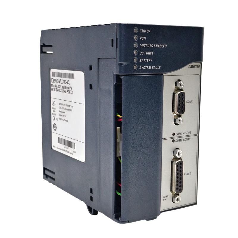
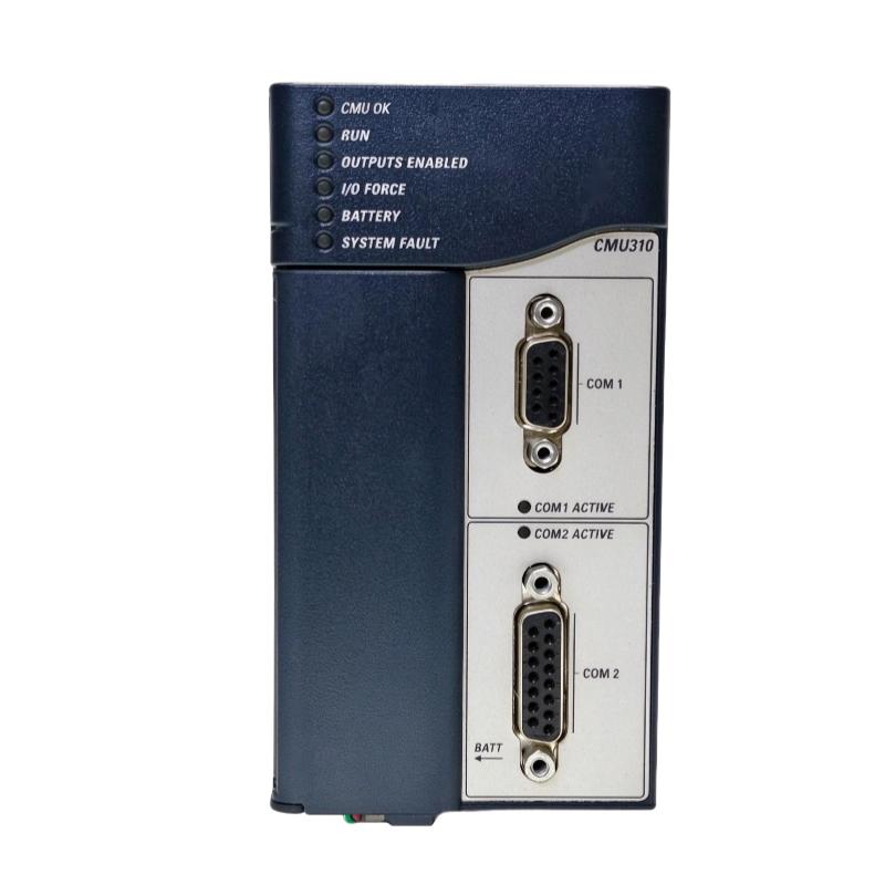
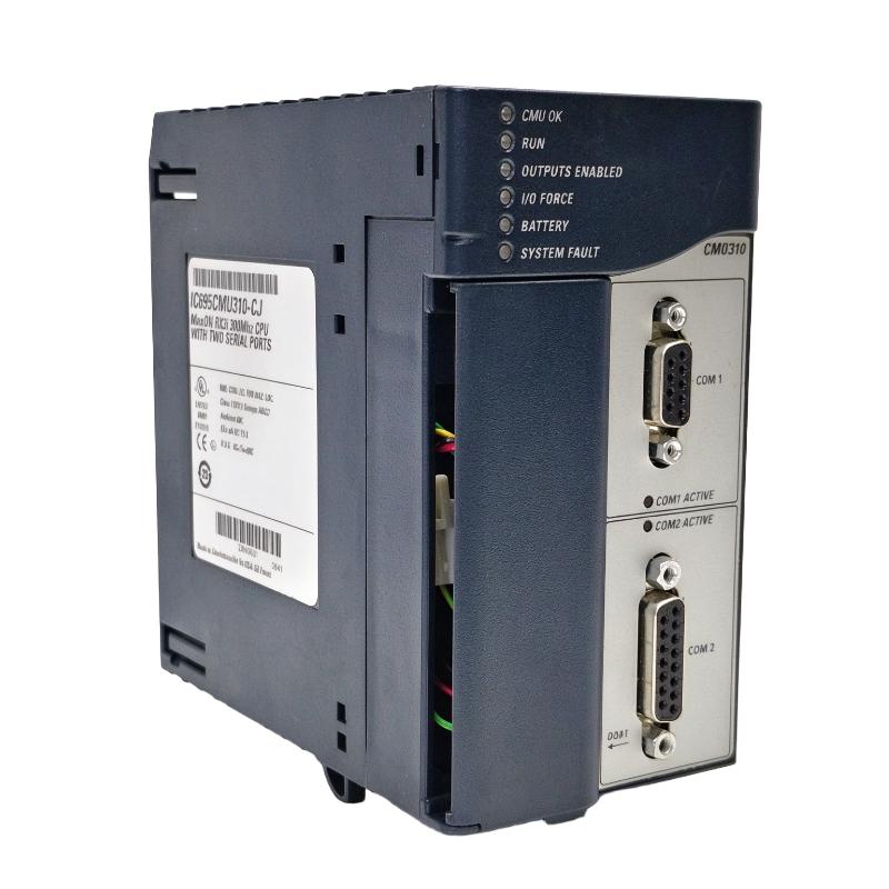
The GE Fanuc IC695CMU310-CJ Redundant Controller Module is a programmable automation controller CPU designed for GE Fanuc PACSystems RX3i systems. It supports Max-ON hot-standby redundancy, allowing two compatible RX3i control systems to coordinate their operations and improve control-system availability.
In industrial automation, controller downtime can interrupt production, affect process stability, and increase maintenance costs. A redundant control architecture helps reduce the consequences of certain controller failures by maintaining a synchronized standby system that can assume control when the active controller becomes unavailable.
The IC695CMU310-CJ is designed for applications that require coordinated control, controller synchronization, and high availability. Typical applications include boiler systems, standby power generation, fuel-handling installations, and manufacturing processes where unexpected interruptions can be costly.
The module provides a 300 MHz processor, user memory, a real-time clock, and built-in serial communication ports. It is designed to operate in an RX3i Universal Backplane and requires the appropriate power supply, Ethernet modules, and Max-ON redundancy software as part of a complete redundant system.
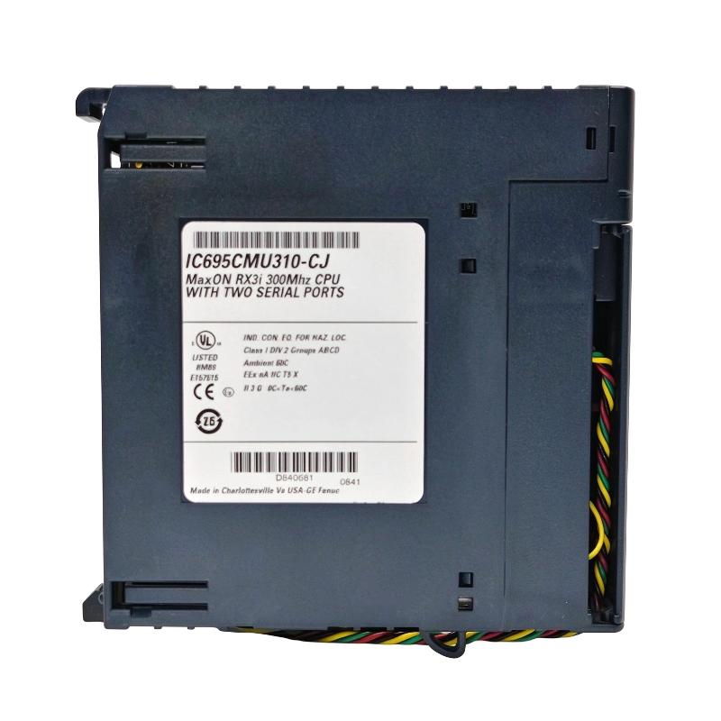
The CJ revision corresponds to firmware release 5.50. This release includes support for Run-mode Store of Ethernet Global Data (EGD) and LREAL data types. When replacing an existing controller, engineers should verify firmware compatibility, application software, communication settings, and the configuration of both controller racks.
The IC695CMU310-CJ is a specialized controller component rather than a standalone PLC. Its functions depend on the surrounding RX3i hardware and correctly configured redundancy software. Selecting the correct CPU revision and compatible system components is essential for reliable operation.
Technical Specifications
| Parameter | Specification |
|---|---|
| Brand | GE Fanuc |
| Product Family | PACSystems RX3i |
| Model | IC695CMU310-CJ |
| Product Type | Max-ON Hot-Standby Redundancy CPU |
| Controller Function | Redundant controller CPU |
| Processor Speed | 300 MHz |
| User Memory | 10 MB battery-backed RAM |
| Non-Volatile Memory | 10 MB flash user memory |
| Backplane Compatibility | RX3i Universal Backplane |
| Serial Communication | RS-232 and RS-485 |
| Ethernet Communication | Supported through compatible Ethernet modules |
| Redundancy Architecture | Two coordinated RX3i control systems |
| Real-Time Clock | Yes |
| Firmware Revision | CJ, Version 5.50 |
| Redundancy Software | Max-ON redundancy software |
| Typical Applications | Power generation, boiler control, fuel handling, manufacturing |
| Dimensions Provided | 160 × 50 × 120 mm |
| Weight Provided | 0.4 kg |
Note: Dimensions and weight are the supplied listing values. Verify the physical measurements and applicable installation documentation before publishing final mechanical specifications.
Function and Working Principle
The IC695CMU310-CJ serves as the processing unit in a PACSystems RX3i Max-ON redundant controller arrangement. It executes the control application and exchanges relevant operating information with the redundant controller through configured Ethernet communication links.
1. Hot-Standby Controller Redundancy
A hot-standby architecture uses two control systems configured to cooperate. One controller acts as the active controller, while the other operates as the standby controller.
The redundant arrangement is designed to reduce interruption if the active controller experiences a fault. When configured correctly, the standby system can assume control according to the redundancy application’s operating rules.
The actual transfer behavior depends on the complete system configuration, synchronization status, application logic, communications, and fault conditions. Redundancy does not guarantee uninterrupted operation under every possible failure.
2. Control Logic Execution
The module executes the application logic used to monitor inputs, evaluate conditions, and determine output actions. The application may include interlocks, process sequences, equipment permissives, alarms, and operating-state management.
The CPU’s processing capability supports the execution of industrial control programs, while the overall performance depends on program complexity, I/O configuration, communications, and the control-system design.
3. Controller Synchronization
The two redundant controllers exchange operating data through dedicated Ethernet LAN connections configured for the Max-ON application. Synchronization helps the standby controller maintain the information required for a coordinated transition when a transfer is necessary.
The Ethernet communication hardware and redundancy software must be configured correctly. Network interruptions, incompatible configuration files, or mismatched controller applications can affect redundancy readiness.
4. Memory and Program Storage
The controller provides battery-backed RAM and non-volatile flash memory for application-related storage. These memory resources support program execution and retention requirements.
Battery condition and memory configuration should be included in routine maintenance. The recommended battery and backup procedures should follow the applicable manufacturer documentation.
5. Serial Communication
The module provides RS-232 and RS-485 serial ports. Depending on the configured application, supported serial functions include SNP, serial I/O, and Modbus master or slave operation through application code.
The selected protocol, wiring arrangement, baud rate, addressing, and connected equipment must be configured consistently. Serial communication availability does not mean that every protocol is automatically active in every application.
Role in Industrial Control Systems
The IC695CMU310-CJ is intended for use within a redundant industrial control architecture. Its role is to execute application logic and support controller coordination, while other modules provide power, I/O, networking, and connection to field equipment.
PLC and PAC Control Architecture
In a PACSystems RX3i installation, the controller works with a compatible Universal Backplane, power supply, Ethernet communication modules, and suitable I/O modules.
Field devices such as pressure transmitters, temperature sensors, limit switches, and actuator feedback devices supply information to the control system. The application logic evaluates these signals and determines the required control actions.
Process Control Coordination
The CPU can execute logic for process sequences, permissives, equipment interlocks, alarm conditions, and operating modes. Depending on the installation, it may coordinate pumps, fans, valves, burners, motors, or other field equipment through suitable I/O and communication components.
Correct application design is essential. The controller should not be treated as a substitute for independently required safety systems or protective devices.
Redundant System Management
The CPU forms part of a paired control arrangement in which both RX3i systems must be configured for the same intended application. Engineers need to maintain compatible program logic, communication settings, and redundancy parameters.
System status should be monitored so that a controller or network fault does not leave the installation operating without its intended level of redundancy.
HMI and Supervisory Integration
An HMI or supervisory control system may display process values, controller status, alarms, and operating conditions. Ethernet communication modules provide the relevant network connectivity when configured for the application.
HMI integration should be planned separately from the dedicated communications used for controller synchronization. The system designer must confirm network requirements, data access, and diagnostic visibility.
Industrial Applications
The IC695CMU310-CJ is suited to control applications that use PACSystems RX3i hardware and require a Max-ON hot-standby redundancy architecture.
1. Power Generation and Standby Power Systems
Power generation installations may use programmable controllers to coordinate auxiliary equipment, monitor operating conditions, and manage process sequences. A redundant controller arrangement can help improve control-system availability where interruptions are operationally significant.
The actual control architecture must be designed around the generator equipment, electrical protection, operating sequence, and applicable safety requirements.
2. Boiler Control Systems
Boiler installations can involve coordinated monitoring of temperatures, pressures, flow conditions, valves, pumps, and auxiliary equipment. A redundant controller arrangement may support the availability of the general process-control layer.
Critical burner management and safety functions require appropriate dedicated safety-rated equipment and approved system design. The IC695CMU310-CJ should not be assumed suitable for SIL 2 or SIL 3 safety applications.
3. Fuel Handling and Loading
Fuel-handling systems may require coordinated control of pumps, valves, conveyors, loading sequences, and permissive conditions. Controller redundancy can reduce the impact of certain CPU failures on the overall automation system.
The application must account for field-device feedback, communications, emergency shutdown requirements, and process-specific protective measures.
4. Manufacturing and Production Lines
Manufacturing installations often depend on coordinated machine sequences, material flow, equipment status, and alarm handling. A redundant control arrangement may be useful where controller downtime can interrupt production.
The benefits depend on the architecture and the failure modes covered by the redundancy arrangement. Field I/O, power, networks, and other shared components can still affect system availability.
5. Continuous Process Industries
Chemical processing, utilities, and other continuous operations may use redundant controllers for selected process-control functions. The controller can execute logic for monitoring, sequencing, and coordination within the limits of the installed system.
System designers should distinguish ordinary process-control requirements from safety instrumented functions and provide separate protection where required.
Installation and System Integration
Correct installation and configuration are essential for the IC695CMU310-CJ to operate as part of a redundant RX3i control system.
1. Verify Backplane Compatibility
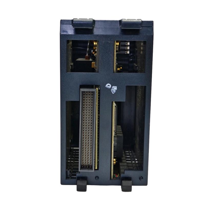
The IC695CMU310-CJ is designed for an RX3i Universal Backplane. Confirm the exact backplane model, slot arrangement, and installation requirements before fitting the module.
The redundant configuration normally uses a separate compatible RX3i system for each controller. Each rack must include the required CPU, power supply, and communication hardware.
2. Confirm Power Requirements
The controller receives its operating power through the backplane. Verify that the selected RX3i power supply supports the complete rack load, including the CPU and all installed modules.
Check power-supply ratings and system grounding before energizing the equipment. A redundant controller design also requires an appropriate power arrangement for each rack.
3. Configure Ethernet Synchronization
The Max-ON architecture uses dedicated Ethernet communication links to exchange operating data between the redundant controllers.
Configure the required Ethernet modules, network addressing, cabling, and redundancy parameters according to the system design. Where the application requires multiple dedicated links, verify each connection and monitor its status.
Do not assume that an ordinary plant network automatically provides the required synchronization behavior. Dedicated redundancy communication should be planned and tested as part of the commissioning process.
4. Check Firmware and Software Compatibility
The IC695CMU310-CJ corresponds to firmware revision 5.50. Verify that the application software and the installed controller revision support the functions used by the project.
Before replacing a controller, record the existing firmware revision, application version, network settings, and redundancy configuration. Changes to firmware or software should be managed through a documented engineering procedure.
5. Inspect Serial Communications
If the installation uses RS-232 or RS-485, confirm the intended protocol, baud rate, parity, addressing, wiring, and termination requirements.
RS-232 and RS-485 have different electrical characteristics and connection requirements. Use the appropriate interface and wiring arrangement for each connected device.
6. Commission the Redundant System
After installation, verify that both controllers start correctly, communicate with the required Ethernet modules, and report the expected redundancy status.
Test the application under controlled conditions, including the approved controller-transfer procedure. Confirm that relevant process states, alarms, and outputs behave as designed.
Record the test results and retain backups of the application and configuration files. For critical installations, follow a formal change-control and commissioning process.
Compatible System Components
The IC695CMU310-CJ requires compatible PACSystems RX3i hardware and Max-ON software. The following components are examples of equipment used in a complete redundant architecture.
| Component | Function | Integration Considerations |
|---|---|---|
| IC695CHS0xx Universal Backplane | Provides the controller rack and module connections | Confirm the exact backplane model and slot requirements |
| IC695PSD040 or compatible RX3i power supply | Supplies rack power | Verify the power supply’s ratings against the rack load |
| IC695ETM001 Ethernet module | Provides Ethernet connectivity for the control system | Confirm the network design and synchronization requirements |
| Max-ON redundancy software | Configures redundant controller operation | Verify software version and project compatibility |
| Compatible RX3i I/O modules | Connect field sensors and actuators | Confirm module type, signal range, wiring, and application requirements |
| HMI or SCADA system | Provides operator monitoring and supervisory control | Verify Ethernet connectivity and supported data access |
| RS-232 / RS-485 devices | Support serial data exchange | Confirm protocol, wiring, and communication settings |
| Engineering workstation | Supports configuration, programming, and diagnostics | Verify compatible engineering tools and access procedures |
| Approved backup battery | Supports battery-backed memory retention | Use the specified battery type and follow replacement procedures |
The components listed above are not necessarily included with the CPU module. Exact part numbers and compatibility should be checked against the installed system’s hardware configuration.
Alternative Models and Replacement Considerations
The IC695CMU310-CJ is a revision-specific controller. Replacement selection must account for the installed hardware, firmware, application, and redundancy architecture.
| Alternative or Related Model | Considerations |
|---|---|
| Another IC695CMU310 revision | Check firmware differences, supported functions, application compatibility, and configuration requirements |
| IC695CRU320 | A different RX3i redundant CPU family with distinct capabilities and hardware requirements; not an automatic drop-in replacement |
| IC695CPU310 or other standard RX3i CPU | May support non-redundant applications, but does not automatically replace a Max-ON redundant CPU |
| Compatible current-generation controller platform | May be considered for a system upgrade, requiring engineering evaluation and possible migration work |
Before selecting a replacement, confirm:
- Complete catalog number and hardware revision.
- Firmware version and supported application features.
- RX3i backplane and power-supply compatibility.
- Ethernet module configuration and synchronization links.
- Max-ON software and project compatibility.
- Serial protocol settings and connected equipment.
- Program backup and restoration procedures.
- Required controller-transfer and recovery tests.
A CPU that fits the rack may not support the same redundancy functions or application behavior. Do not substitute a different controller solely because it belongs to the same product family.
Key Advantages
Hot-Standby Redundancy Support
The module is designed for a Max-ON architecture using two coordinated RX3i control systems, helping reduce the impact of certain controller failures.
300 MHz Processing
Its processor supports execution of industrial control logic, with actual application performance dependent on program complexity and system configuration.
Dedicated Controller Synchronization
The redundant architecture uses configured Ethernet links to exchange operating data between the controllers.
Integrated Serial Ports
Built-in RS-232 and RS-485 interfaces support suitable serial communication applications without requiring a separate serial interface for every connection.
Memory and Real-Time Clock
The module provides battery-backed RAM, non-volatile flash memory, and a real-time clock for supported controller functions.
Compatibility with RX3i Systems
The CPU is designed for use with the RX3i Universal Backplane and compatible modules, enabling integration into modular industrial control architectures.
Support for Legacy Industrial Systems
For plants already using PACSystems RX3i Max-ON installations, identifying the exact CPU revision can help maintenance teams preserve existing configurations and plan replacement work more accurately.
Technical FAQs
1. What is the GE Fanuc IC695CMU310-CJ?
It is a PACSystems RX3i Max-ON hot-standby redundancy CPU module used in a compatible redundant controller architecture.
2. What does hot-standby redundancy mean?
Hot-standby redundancy uses an active control system and a standby system configured to take over under supported failure conditions. The result depends on correct synchronization, system design, and successful commissioning.
3. What is the processor speed?
The IC695CMU310 is specified with a 300 MHz processor. Actual control performance depends on the application program and the complete system configuration.
4. What communication ports are available?
The CPU provides RS-232 and RS-485 serial ports. Ethernet communication for the redundant architecture is provided through compatible Ethernet modules.
5. What is the CJ firmware revision?
The CJ revision corresponds to firmware release 5.50, which includes support for Run-mode Store of Ethernet Global Data and LREAL data types.
6. Does the module work in any RX3i rack?
It is designed for the RX3i Universal Backplane. Confirm the exact backplane and system configuration before installation, particularly for a redundant system.
7. Can this CPU be used as a standalone replacement for a standard RX3i CPU?
Not automatically. It is intended for a Max-ON redundant architecture and requires compatible hardware and redundancy software. Replacing a standard CPU with this model requires a full compatibility review.
8. Is the IC695CMU310-CJ a safety-rated controller?
It should not be treated as a safety-rated controller for SIL 2 or SIL 3 functions. Safety-related applications require suitable certified equipment and a design that meets the applicable standards.
9. What should be checked before purchasing a used module?
Verify the full catalog number, CJ revision, physical condition, connector condition, available test results, and compatibility with the existing project. Confirm the return policy and warranty terms, especially for critical applications.
10. Why should firmware be checked before replacement?
Different revisions can support different functions and fixes. A replacement must be compatible with the existing application, communication setup, and redundancy configuration to avoid commissioning or operational problems.
Procurement and Maintenance Recommendations
When purchasing the GE Fanuc IC695CMU310-CJ, verify the complete catalog number and firmware revision rather than relying only on the description “RX3i redundant CPU.”
For replacement projects, confirm the existing backplane, power supply, Ethernet modules, Max-ON software, serial interfaces, and controller program. Ask the supplier to confirm the condition of the module and provide clear photographs of its label and connectors where possible.
For used or refurbished equipment, request available test information and clarify warranty and return conditions. Confirm that the supplied unit is the required CJ revision and that it can be integrated into the existing control architecture.
Routine maintenance should include monitoring controller and redundancy status, checking communication links, inspecting the rack environment, and maintaining current backups of the application and configuration files. Battery condition should be monitored according to the manufacturer’s instructions.
When servicing a redundant system, avoid changing the active and standby configurations without a documented procedure. Confirm the current system state, verify the synchronization status, and follow approved commissioning and recovery steps before returning the installation to normal operation.
Conclusion
The GE Fanuc IC695CMU310-CJ PACSystems RX3i Redundant Controller Module is a Max-ON hot-standby CPU designed for industrial automation systems that require coordinated redundant control. Its 300 MHz processor, memory resources, RS-232 and RS-485 serial interfaces, and Ethernet-based synchronization architecture support its role in compatible RX3i installations.
Successful deployment depends on correct backplane selection, power and Ethernet configuration, firmware compatibility, and redundancy software setup. For maintenance and replacement projects, verifying the complete catalog number and testing the redundant system are essential steps toward reliable industrial control.