

ProductPRODUCT
Featured products
Contact Us
- Allen Bradley
- PN-271938
- Optical Interface Board
- USA
- 200 x 150 x 100 mm
- 0.5 kg
- Xiamen, China
- New & In Stock
- T/T, PayPal, Western Union
- 1 Year
- 1-3 Working Days
- DHL, UPS, TNT, FedEx and EMS.
- 24-Hour Service
- COO
- 6
Our advantage

Global Logistics
We have a 10-year logistics and express cooperation agreement, so our products can be shipped to any place in the world.

Brand new and original
Our products are imported in bulk from the place of origin. Because of the cooperative relationship, our products are all original and 100% new.

24-hour service
We provide 7*24 hours service to our customers. We will be there whenever you need us.

Price advantage
All our products are priced very favorably because we have our own warehouse and supply.
| Company Information | |||
| [email protected] | |||
| Mobile | +8615980777398 | ||
| +8615980777398 | |||
| 15980777398 |
Product Overview
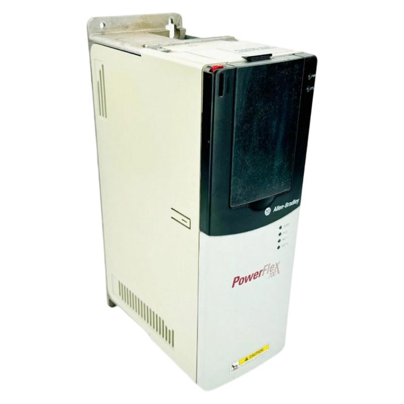
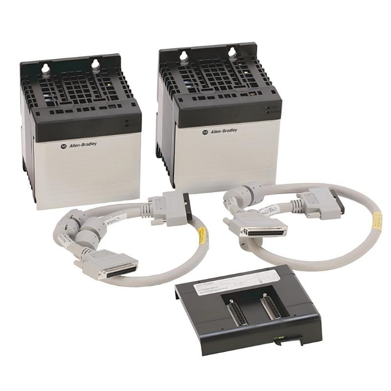
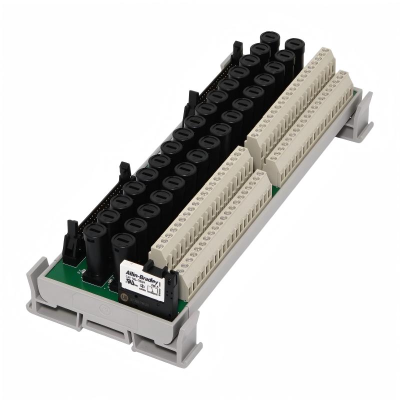
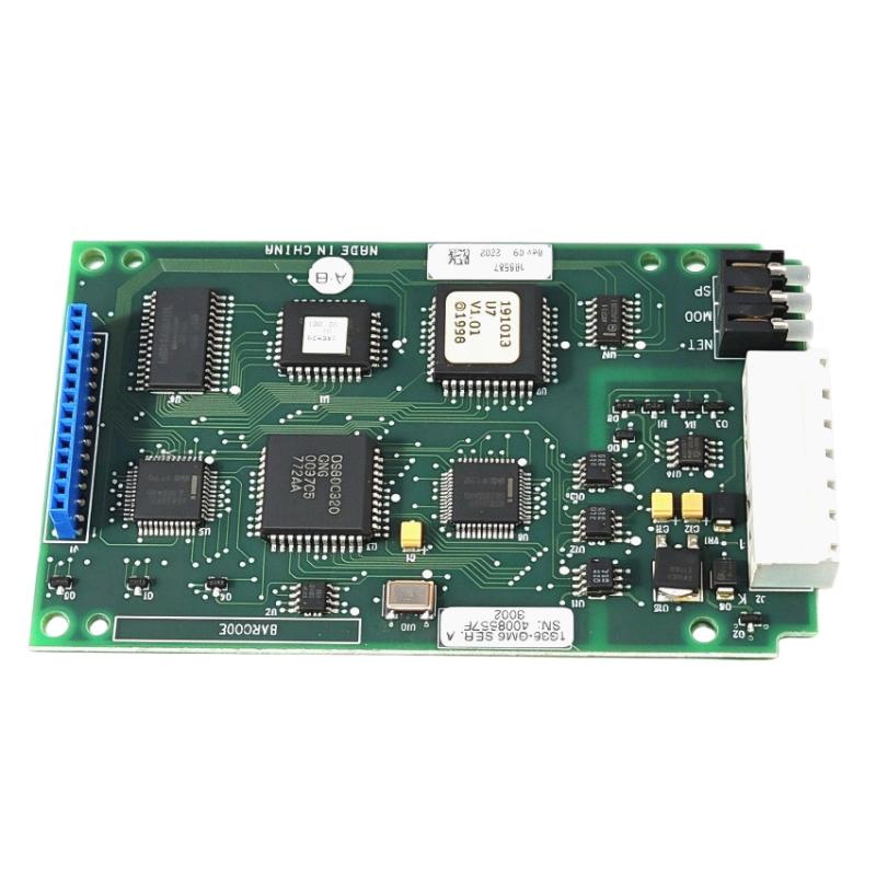
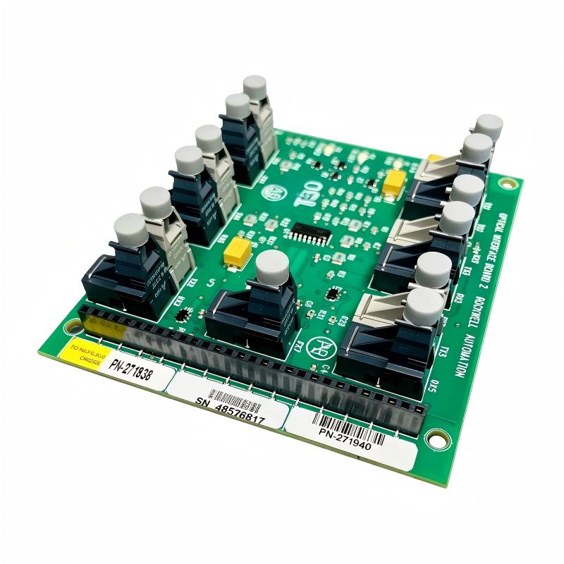
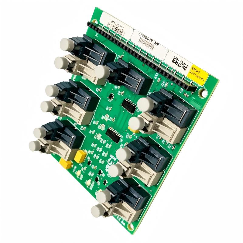
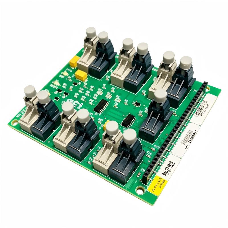
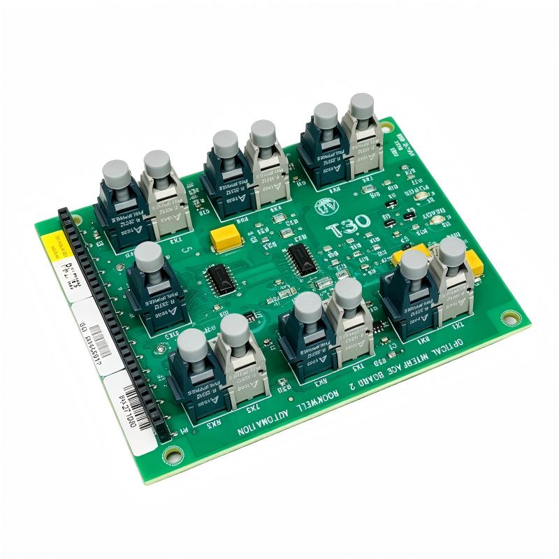
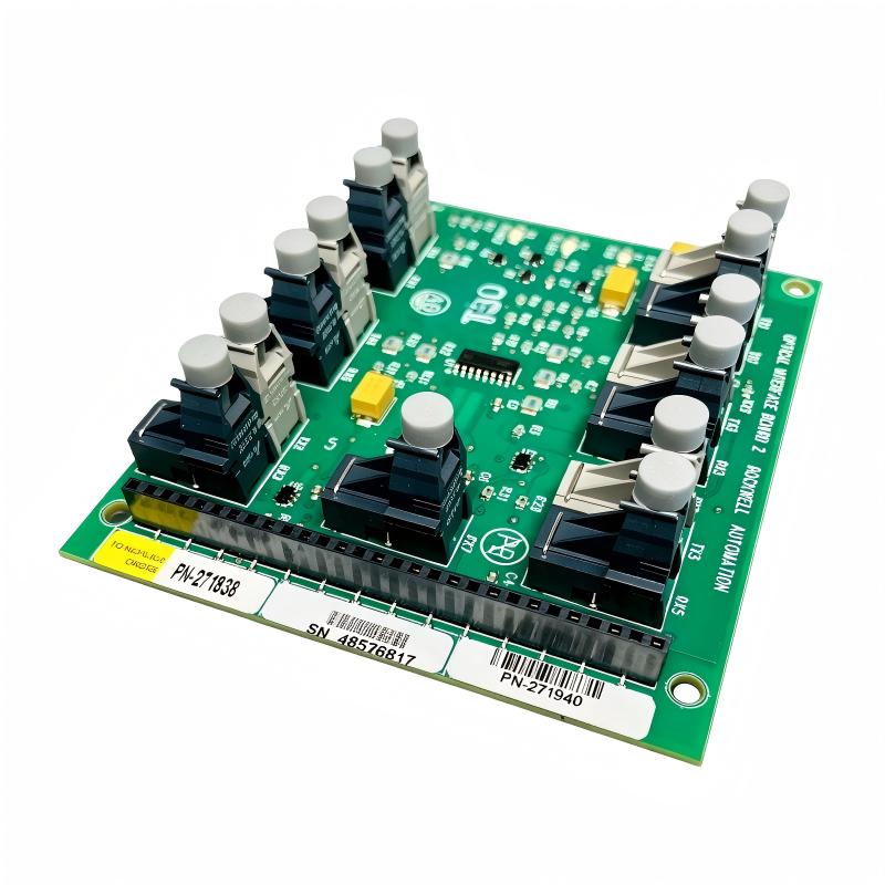
The Allen-Bradley PN-271938 Optical Interface Board 2 (OIB2) is an industrial electronic circuit board associated with the PowerFlex 7000 medium-voltage drive system from Rockwell Automation. It is designed for use within compatible drive architectures that rely on optical interfaces to support signal communication between system components.
Optical communication is important in medium-voltage drive applications because it helps transfer signals between designated control and power-related assemblies while reducing susceptibility to electromagnetic interference along the optical transmission path. The optical interface board forms part of the drive’s internal communication and interface architecture rather than functioning as a standalone PLC controller or general-purpose network adapter.
The PN-271938 is relevant to industrial maintenance, drive servicing, equipment refurbishment, and spare-parts management. When an existing PowerFlex 7000 system experiences an optical communication fault or requires scheduled component replacement, identifying the correct board is essential for maintaining compatibility with the installed drive configuration.
For maintenance engineers, selecting the correct optical interface board requires more than matching the model number alone. The installed drive generation, hardware configuration, board revision, and applicable service documentation should all be considered before replacement.
The Allen-Bradley PN-271938 is therefore best understood as a specialized industrial replacement component for compatible PowerFlex 7000 equipment. It should be installed and tested by qualified personnel familiar with medium-voltage drive systems and the associated safety procedures.
Technical Specifications
| Parameter | Specification |
|---|---|
| Brand | Allen-Bradley |
| Manufacturer | Rockwell Automation |
| Model Number | PN-271938 |
| Product Name | Optical Interface Board 2 |
| Abbreviation | OIB2 |
| Product Type | Optical Interface Printed Circuit Board |
| Associated Equipment | Compatible PowerFlex 7000 medium-voltage drives |
| Dimensions | 200 × 150 × 100 mm |
| Weight | 0.5 kg |
| Primary Function | Optical interface and signal communication within the drive system |
| Installation Type | Internal equipment assembly; verify the specific drive configuration |
| Application | Medium-voltage motor drive maintenance and repair |
| Power Requirement | Determined by the host equipment and board design |
| Replacement Requirement | Verify the exact part number, revision, and drive compatibility |
Specification note: The dimensions and weight are based on the supplied product information. Confirm the physical dimensions, mounting arrangement, and revision details against the actual board and equipment documentation before ordering.
Function and Working Principle
1. Optical Signal Interface
The principal purpose of an optical interface board is to support communication through designated optical signal paths within compatible equipment.
In industrial drive systems, control commands, feedback information, and status signals may need to pass between different electronic assemblies. Optical communication can provide a suitable transmission method where electrical isolation and immunity to electromagnetic interference are important design considerations.
The PN-271938 OIB2 is associated with the PowerFlex 7000 drive architecture. Its exact signal assignments and interfaces depend on the system design and should be verified using the appropriate technical documentation.
2. Communication Between Drive Assemblies
A medium-voltage drive contains multiple coordinated subsystems. These may include control electronics, gate-driver-related assemblies, feedback interfaces, protective functions, and power-conversion components.
Communication between these subsystems is necessary for coordinated operation. The optical interface board supports the relevant interface functions within the compatible drive configuration.
A fault in an optical communication path may affect the ability of the system to exchange expected signals. However, a communication alarm does not automatically mean that the OIB2 board itself has failed. Optical cables, connectors, associated electronic boards, power supplies, and configuration issues should also be considered during troubleshooting.
3. Electrical Isolation and Noise Immunity
Optical communication uses light to transmit signals through fiber rather than relying exclusively on electrical signals through copper conductors. This can help reduce the impact of electromagnetic interference and support electrical isolation between designated circuit sections.
These characteristics are particularly useful in industrial environments where high-power switching, motor currents, and power-conversion equipment create demanding electromagnetic conditions.
The actual isolation characteristics and protection boundaries depend on the complete equipment design. They should not be inferred from the board name alone.
4. Integration With the Host Drive
The PN-271938 is not a standalone motor controller. Its function is tied to the compatible drive assembly in which it is installed.
The host drive provides the necessary electrical power, control logic, signal-processing resources, and system-level protection. The optical interface board operates as one part of this larger architecture.
For this reason, replacement must follow the drive manufacturer’s service instructions, including any required shutdown, inspection, configuration, and post-replacement verification procedures.
Role in PowerFlex 7000 Medium-Voltage Drive Systems
The Allen-Bradley PowerFlex 7000 is designed for industrial motor-control applications where medium-voltage drive technology is required. Such systems are commonly used to control large motors in demanding industrial processes.
Within a drive installation, specialized electronic boards perform different functions. Some support control processing, others handle feedback or power-related interfaces, and dedicated communication assemblies transfer signals between system sections.
The PN-271938 OIB2 belongs to this specialized interface category. Its importance comes from its role within the drive’s internal architecture rather than from independently controlling a complete process.
Correct operation of the relevant interface circuitry helps the drive maintain the intended communication relationships between compatible assemblies. If a board or associated optical path develops a fault, the resulting symptoms may include communication errors, diagnostic alarms, or an inability to complete the expected startup or operating sequence.
A structured troubleshooting procedure should therefore examine the complete communication path rather than replacing components based only on a single alarm.
Industrial Applications
1. Mining and Mineral Processing
Mining operations use large motors for equipment such as conveyors, pumps, fans, and material-handling systems. Medium-voltage drives can help regulate motor speed and operating conditions in these applications.
The PN-271938 may be relevant to maintenance inventories for compatible PowerFlex 7000 installations used in such facilities.
2. Oil and Gas Facilities
Oil and gas operations use high-power motors in pumping, compression, and other process-related applications. Drive reliability is important because equipment interruptions can affect production and maintenance schedules.
Specialized interface boards may be required when servicing compatible drive systems. Before selecting PN-271938 for a particular installation, the equipment model and board configuration must be verified.
3. Water and Wastewater Treatment
Large pumps and ventilation equipment are common in water and wastewater infrastructure. Medium-voltage motor-control systems may be used where motor power requirements justify this type of drive.
The OIB2 can be considered as a replacement component only when the installed equipment uses the corresponding board assembly.
4. Cement and Heavy Manufacturing
Cement production and other heavy industries use large motors in equipment such as fans, mills, and material-handling systems.
In these facilities, planned maintenance and suitable spare-parts inventories can help reduce the time needed to investigate and repair drive faults. Correctly identifying the optical interface board is an important part of that process.
5. Industrial Power and Process Facilities
Industrial plants with large rotating machinery may depend on medium-voltage drives for process control and energy management.
Maintaining the relevant electronic assemblies can support equipment serviceability. Nevertheless, a board replacement should be based on documented compatibility and a confirmed fault diagnosis rather than preventive replacement without technical justification.
Installation and System Integration
Step 1: Identify the Drive Model
Before installing the PN-271938, identify the complete PowerFlex 7000 drive model and its configuration. Record the drive nameplate information and the existing board part number.
Different drive configurations may use different interface arrangements. Do not assume that every PowerFlex 7000 assembly accepts every optical interface board revision.
Step 2: Confirm the Part Number and Revision
Check the label on the existing board and compare it with the replacement. Verify the complete catalog or assembly number, revision information, and any applicable service documentation.
If the existing board is unavailable for inspection, use the equipment’s bill of materials, maintenance records, or approved parts documentation to establish the required component.
Step 3: Follow Medium-Voltage Safety Procedures
PowerFlex 7000 systems involve potentially hazardous electrical energy. Installation and maintenance must be performed by qualified personnel following the manufacturer’s safety procedures and the site’s electrical safety program.
The drive must be placed in the prescribed safe maintenance condition. Required isolation, lockout/tagout, discharge waiting periods, and verification of absence of hazardous voltage must be completed before internal access.
Never rely solely on a stopped motor or a disabled control command as proof that the equipment is electrically safe.
Step 4: Inspect the Board and Connectors
Before installation, inspect the replacement board for visible damage, contamination, bent components, damaged connectors, or signs of improper storage.
Inspect the associated optical connectors and cables according to the manufacturer’s procedures. Contaminated connectors, damaged fibers, or loose connections can cause communication problems even when the board itself is functional.
Handle the board using appropriate electrostatic-discharge precautions. Avoid touching exposed electronic components and connector contacts unnecessarily.
Step 5: Install According to the Approved Procedure
Install the board only in the designated location and orientation specified for the compatible drive configuration.
Follow the manufacturer’s instructions for mounting hardware, connector engagement, cable routing, and any required settings. Do not force connectors or modify the board to fit an assembly.
Because the OIB2 is part of a specialized drive architecture, improvised wiring or undocumented substitutions may introduce additional faults or create unsafe operating conditions.
Step 6: Perform Post-Replacement Verification
After installation, complete the required inspection and verification steps before returning the drive to service.
Check the applicable diagnostic indicators, system alarms, optical communication paths, and other verification items specified by the service documentation. Perform any required functional checks using the approved procedure.
Where the replacement is part of a safety-related maintenance task, complete all prescribed safety-function verification steps before releasing the equipment for operation.
Step 7: Update Maintenance Records
Record the replaced part number, revision, installation date, equipment identification, and test results. Document any unresolved alarms or follow-up actions.
Accurate records help maintenance teams identify recurring failures, manage spare-parts inventories, and reduce delays during future repairs.
Compatible System Components
The PN-271938 is associated with PowerFlex 7000 equipment, but compatibility with a particular assembly must be confirmed before installation.
| Component Category | Relationship to PN-271938 | Verification Requirement |
|---|---|---|
| PowerFlex 7000 drive system | Host equipment associated with the OIB2 | Confirm the exact drive configuration |
| Optical interface base board | Related interface assembly within applicable drive architecture | Verify the corresponding board and revision requirements |
| Optical fiber cables | May form part of the communication path | Check connector type, routing, and optical specifications |
| Control and interface electronics | Exchange signals within the drive system | Confirm the signal architecture in the service documentation |
| Gate-driver-related assemblies | May participate in drive power-conversion control architecture | Confirm the specific model and interface arrangement |
| Drive diagnostic system | Provides information used during fault investigation | Review the actual alarm and troubleshooting procedure |
This table describes functional relationships rather than guaranteeing direct compatibility with every component in each category. Always use the approved parts list for the specific drive.
Replacement and Alternative Selection
Selecting a replacement for the Allen-Bradley PN-271938 requires careful verification. An optical interface board with a similar appearance or general description may have a different electrical interface, optical assignment, mounting arrangement, or intended application.
| Selection Factor | Recommended Check |
|---|---|
| Part number | Confirm PN-271938 |
| Board identification | Verify that the board is identified as Optical Interface Board 2 (OIB2) |
| Drive compatibility | Match the installed PowerFlex 7000 configuration |
| Hardware revision | Check revision and substitution requirements |
| Physical dimensions | Confirm against the supplied 200 × 150 × 100 mm specification and actual assembly |
| Weight | Supplied reference value: 0.5 kg |
| Connector condition | Inspect optical and electrical connectors |
| Product condition | Confirm new, unused surplus, or refurbished status |
| Availability | Verify actual stock and delivery lead time |
| Warranty | Clarify the supplier’s warranty and return terms |
If an exact replacement is unavailable, do not select an alternative solely because it is described as an optical interface board. A substitute should be used only when its compatibility has been established through the applicable equipment documentation or an authorized technical assessment.
Key Advantages
1. Designed for Specialized Drive Applications
The PN-271938 is associated with the PowerFlex 7000 medium-voltage drive platform, making correct model identification important for drive maintenance and repair.
2. Supports Optical Interface Functions
Optical communication can help transfer signals between designated drive assemblies while reducing susceptibility to electromagnetic interference along the optical path.
3. Suitable for Spare-Parts Planning
Maintaining an accurate record of the required OIB2 part number can help industrial facilities plan repairs and manage spare-parts availability.
4. Supports Equipment Serviceability
When a board is confirmed faulty and the correct replacement is available, replacing the affected component according to approved procedures can support the restoration of the drive system.
5. Relevant to Industrial Maintenance
The board is a specialized component for maintenance teams servicing compatible medium-voltage drive installations. Correct identification can help prevent delays caused by ordering an incompatible assembly.
Technical FAQs
Q1: What is the Allen-Bradley PN-271938?
The PN-271938 is identified as the Allen-Bradley Optical Interface Board 2 (OIB2), associated with compatible PowerFlex 7000 medium-voltage drive systems.
Q2: Is PN-271938 an HMI operator interface board?
No. Although some reseller catalogs place the part under a broad operator-interface category, its more specific product description identifies it as an Optical Interface Board 2 for PowerFlex 7000 applications.
Q3: What is the primary function of the OIB2?
It supports optical interface and signal communication functions within the compatible drive architecture. Exact signal assignments depend on the equipment configuration.
Q4: What are the dimensions and weight?
The supplied dimensions are 200 × 150 × 100 mm, and the supplied weight is 0.5 kg. Confirm these measurements against the actual product before using them for mechanical planning or shipping calculations.
Q5: Can PN-271938 be installed in any PowerFlex 7000 drive?
Compatibility should not be assumed across every drive configuration. Confirm the complete drive model, board revision, and approved parts documentation before installation.
Q6: Can an optical communication alarm confirm that the board has failed?
No. A communication alarm may result from a damaged fiber cable, contaminated connector, faulty associated board, power issue, or other system problem. Follow the drive’s diagnostic procedure to isolate the cause.
Q7: Does replacing the OIB2 require special precautions?
Yes. PowerFlex 7000 systems can contain hazardous medium-voltage electrical energy. Only qualified personnel should perform maintenance, using the prescribed isolation, discharge, verification, and post-maintenance procedures.
Q8: What should buyers verify before ordering PN-271938?
Verify the full part number, board identification, drive compatibility, revision, product condition, supplier warranty, and availability. If possible, compare the offered board with the installed unit and its equipment documentation.
Procurement and Maintenance Recommendations
For industrial maintenance departments, system integrators, and spare-parts distributors, the Allen-Bradley PN-271938 should be purchased against the exact requirements of the installed PowerFlex 7000 system.
Before placing an order, provide the supplier with the full part number and confirm that the offered item is the Optical Interface Board 2 (OIB2). Ask for clear photographs of the board label and connectors where product identification is uncertain.
For surplus or refurbished components, confirm the inspection and testing process, product condition, warranty coverage, and return policy. Packaging should protect the board against electrostatic discharge, moisture, shock, and mechanical damage during international transport.
If the board is required for an urgent repair, verify actual stock and dispatch timing rather than relying only on a general product listing. For long-term maintenance planning, retain the equipment identification, installed revision, and approved replacement information in the site’s spare-parts database.
The board should not be replaced without a reasonable diagnosis of the fault. Reviewing the relevant drive alarms and inspecting the complete optical communication path can help avoid unnecessary component replacement and reduce maintenance costs.
Conclusion
The Allen-Bradley PN-271938 Optical Interface Board 2 (OIB2) is a specialized electronic interface component associated with PowerFlex 7000 medium-voltage drive systems. Its role relates to optical communication within the drive architecture, making correct part identification and configuration verification essential for replacement and maintenance work.
For industrial users, the most important considerations are drive compatibility, board revision, connector condition, safe installation, and post-replacement verification. By checking these details before purchasing and following the approved service procedures, maintenance teams can make better-informed decisions when sourcing the PN-271938 for industrial drive applications.
Product Summary: Allen-Bradley PN-271938 | Optical Interface Board 2 (OIB2) | Associated with PowerFlex 7000 | Dimensions: 200 × 150 × 100 mm | Weight: 0.5 kg