

ProductPRODUCT
Featured products
Contact Us
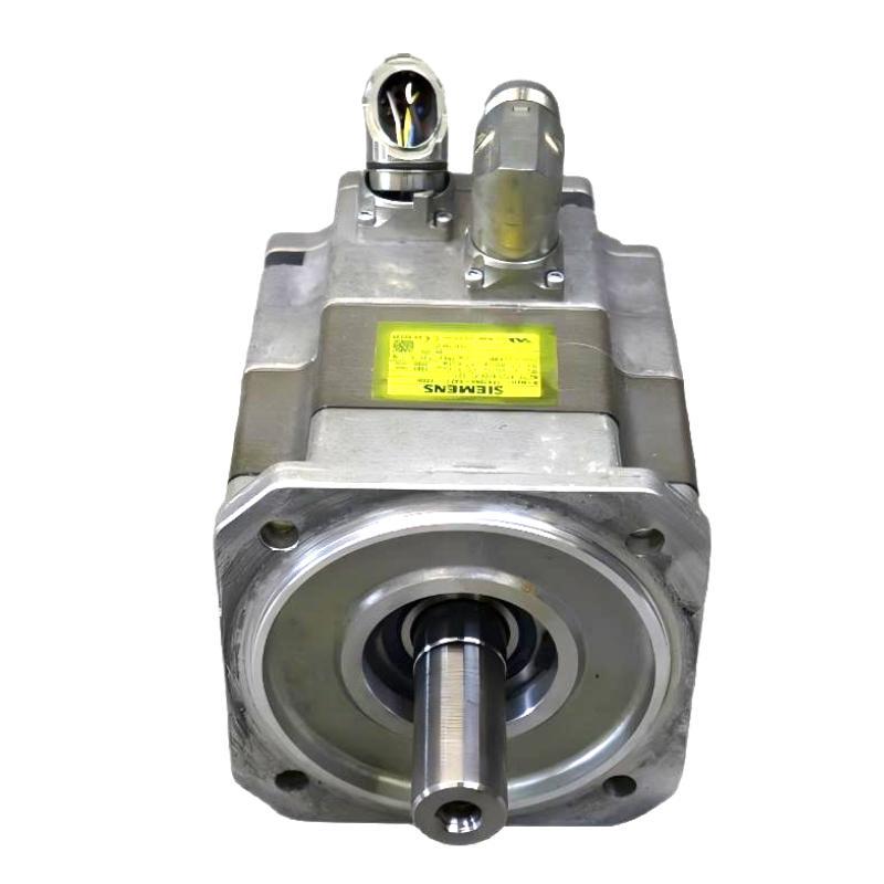
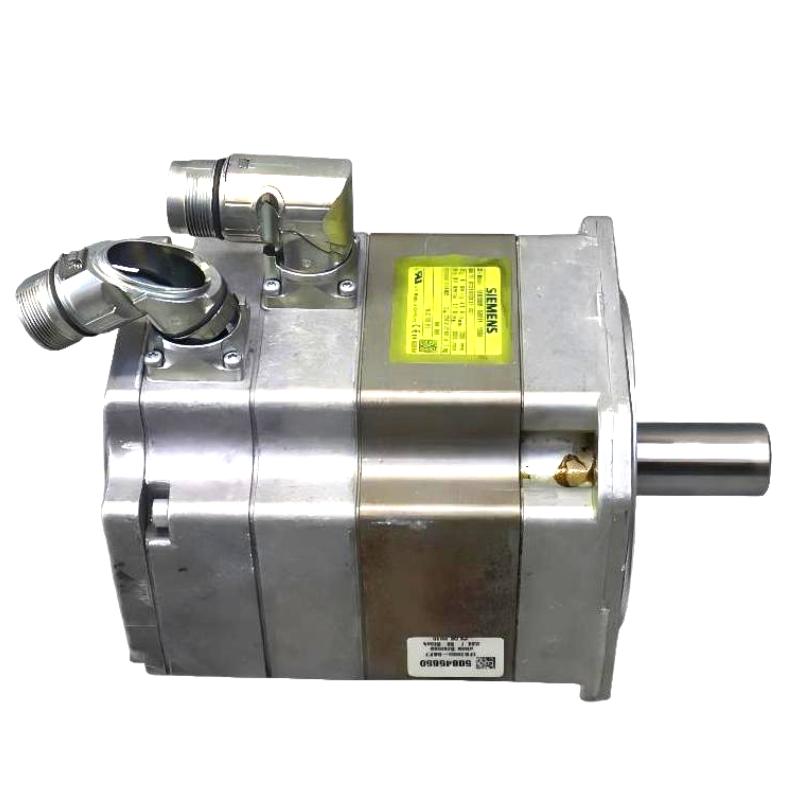
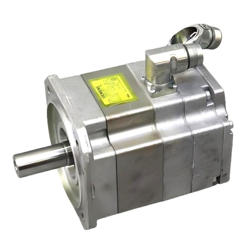
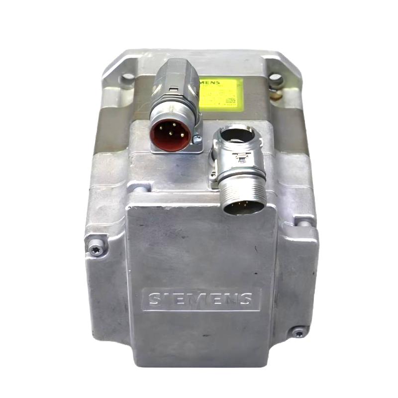
- Siemens
- 1FK7060-5AF71-1SG0
- Synchronous Servo Motor
- Germany
- 63 mm
- 7.003 kg
- Xiamen, China
- New & In Stock
- T/T, PayPal, Western Union
- 1 Year
- 1-3 Working Days
- DHL, UPS, TNT, FedEx and EMS.
- 24-Hour Service
- COO
- 5
Our advantage

Global Logistics
We have a 10-year logistics and express cooperation agreement, so our products can be shipped to any place in the world.

Brand new and original
Our products are imported in bulk from the place of origin. Because of the cooperative relationship, our products are all original and 100% new.

24-hour service
We provide 7*24 hours service to our customers. We will be there whenever you need us.

Price advantage
All our products are priced very favorably because we have our own warehouse and supply.
| Company Information | |||
| [email protected] | |||
| Mobile | +8615980777398 | ||
| +8615980777398 | |||
| 15980777398 |
Product Overview
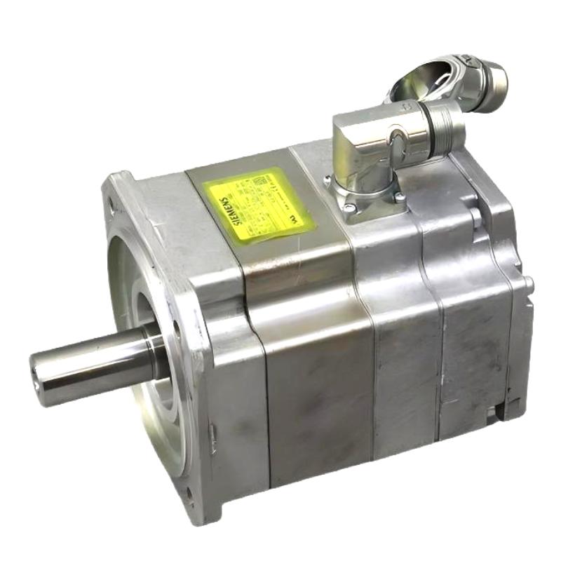
The Siemens 1FK7060-5AF71-1SG0 SIMOTICS S Synchronous Servo Motor is a permanent-magnet synchronous motor from the SIMOTICS S 1FK7 Compact family. It is intended for servo-driven machinery that requires controlled rotary movement, repeatable positioning, and coordinated operation with an automation system. Typical applications include machine-tool feed axes, assembly equipment, indexing mechanisms, and automated material-handling systems.
Unlike a conventional motor operating primarily at a steady speed, a servo motor frequently accelerates, decelerates, and changes direction in response to machine commands. In an automated assembly cell, for example, the motor may move a fixture into position, maintain controlled movement during a process step, and return to a defined starting point for the next cycle. The drive manages the motor’s electrical operation while the machine controller coordinates the movement with the rest of the equipment.
The 1FK7060-5AF71-1SG0 uses natural cooling and a multipole resolver for rotor-position feedback. The resolver works with compatible drive equipment to supply information needed for motor control. Unlike an absolute encoder that reports an absolute position through its encoded data, a resolver produces electrical signals from which the drive determines rotor position. The drive’s feedback interface and configuration must therefore match the motor’s resolver system.
This version has a plain shaft and no integrated holding brake. The plain shaft can be connected to a suitable coupling for direct torque transmission, provided the coupling matches the shaft interface and mechanical requirements. Because there is no built-in holding brake, an application that must retain a load after the motor is de-energized may need a separate mechanical holding arrangement.
The motor’s IP64 protection rating is relevant when evaluating the installation environment. Dust protection and resistance to splashing water should be considered alongside the condition of the connectors, cable interfaces, and surrounding enclosure. The protection rating of the motor does not automatically extend to the entire installed machine assembly.
When integrating the 1FK7060-5AF71-1SG0 into an existing axis, the main engineering considerations are resolver compatibility, drive sizing, coupling alignment, load inertia, and thermal duty. A motor may rotate normally yet still produce poor positioning behavior if the feedback signals are incorrectly configured or the mechanical transmission introduces backlash. Assessing the motor as part of the complete servo axis helps distinguish electrical faults from mechanical problems.
Technical Specifications
| Parameter | Specification |
|---|---|
| Manufacturer | Siemens |
| Model | 1FK7060-5AF71-1SG0 |
| Product Type | SIMOTICS S Synchronous Servo Motor |
| Product Family | SIMOTICS S 1FK7 Compact |
| Motor Technology | Permanent-Magnet Synchronous Motor |
| Motor Frame | 1FK7060 |
| Rated Speed | 3,000 rpm |
| Rated Power | 1.5 kW |
| Rated Torque at 100 K Temperature Rise | 4.7 Nm |
| Static Torque at 100 K Temperature Rise | 6.0 Nm |
| Rated Current | 3.7 A |
| Number of Poles | 8 |
| Cooling Method | Natural Cooling |
| Encoder System | Multipole Resolver |
| Feedback Principle | Resolver-based rotor-position feedback |
| Shaft Design | Plain Shaft |
| Holding Brake | Not included |
| Mounting Arrangement | IM B5, IM V1, IM V3 |
| Electrical Connections | Rotatable power and signal connectors |
| Connector Rotation | 270° |
| Temperature Monitoring | KTY84 temperature sensor in the stator winding |
| Protection Rating | IP64 |
| Vibration Severity Grade | Grade A |
| Shaft Height | 63 mm |
| Weight | 7.003 kg |
Product Features
- Permanent-magnet synchronous construction: Converts controlled electrical input into rotary torque for servo applications.
- 1FK7 Compact motor platform: Supports integration into industrial machinery using the corresponding mounting arrangement.
- 3,000 rpm rated speed: Suits applications requiring regulated rotary motion within the motor’s operating range.
- Multipole resolver feedback: Supplies rotor-position information for compatible servo-drive control.
- Plain-shaft design: Supports coupling-based torque transmission without a fitted key.
- No integrated holding brake: Suits applications where a motor-mounted brake is not required.
- Natural cooling: Dissipates operating heat through the motor’s specified thermal arrangement.
- Rotatable connectors: Allows the power and signal connections to be oriented to suit the installation.
- Integrated temperature monitoring: The KTY84 sensor supports monitoring of stator winding temperature.
- IP64 protection: Provides protection against dust ingress and splashing water under the specified conditions.
Working Principle
The 1FK7060-5AF71-1SG0 generates torque through the interaction between its permanent-magnet rotor and the magnetic field produced by the stator windings. A compatible servo drive regulates the current supplied to the windings, allowing the motor to accelerate, decelerate, and maintain the commanded speed or position.
Motion Command → Servo Drive → Stator Magnetic Field → Rotor Rotation → Mechanical Load
When the machine controller requests movement, the drive processes the command and controls the electrical current supplied to the motor. The resulting magnetic field produces torque at the shaft. During acceleration, the motor must overcome the inertia of the connected mechanism as well as the resistance imposed by the load.
The multipole resolver supplies electrical signals associated with rotor position. The compatible drive interprets these signals to determine rotor position and regulate motor operation. Correct resolver wiring and feedback configuration are essential: incorrect connections or signal interpretation can cause feedback faults or prevent the axis from operating correctly.
Consider a machine that moves a component between two processing stations. The controller issues a movement command, and the drive accelerates the motor to move the mechanism. As the axis approaches the target, the drive adjusts motor torque to achieve the required motion profile. The resolver feedback helps the drive regulate the movement, while the controller determines when the next production step can begin.
The plain shaft transfers torque through a suitable coupling. The coupling must accommodate the actual shaft interface, operating speed, and transmitted torque. Poor alignment can introduce radial loads, vibration, and unnecessary bearing stress, while mechanical backlash can reduce positioning repeatability.
Thermal behavior also affects the motor’s operating limits. Current flowing through the stator windings produces heat, particularly during high-torque operation and repeated acceleration cycles. The integrated KTY84 temperature sensor provides a means of monitoring winding temperature through the compatible drive system. Thermal protection and operating limits should be configured according to the applicable motor and drive requirements.
Because this model does not include a holding brake, its servo torque should not be treated as a mechanical locking function after power is removed. Where an axis must remain stationary under gravity or another external force, the machine may require a separate holding device.
Role in a Siemens SIMOTICS S Servo Drive System
The 1FK7060-5AF71-1SG0 acts as the electromechanical output of a servo-controlled axis. The servo drive regulates the motor’s electrical operation, while the resolver provides rotor-position feedback. A machine controller coordinates the axis with sensors, actuators, and the production sequence.
Machine Controller → Compatible Servo Drive → 1FK7060-5AF71-1SG0 → Mechanical Coupling → Machine Axis
| System Component | Function |
|---|---|
| Siemens 1FK7060-5AF71-1SG0 | Converts electrical input into controlled rotary movement |
| Compatible Servo Drive | Regulates motor current and executes motion-control functions |
| Machine Controller | Generates motion commands and coordinates machine operations |
| Multipole Resolver | Supplies rotor-position signals for drive control |
| Resolver Signal Connection | Transmits feedback signals to compatible drive equipment |
| Motor Power Cable | Supplies electrical power from the drive |
| KTY84 Temperature Sensor | Supports monitoring of stator winding temperature |
| Mechanical Coupling | Transfers torque from the plain shaft to the driven mechanism |
| Gearbox or Transmission | Adjusts speed and torque where required by the application |
| Machine Axis | Performs the required rotary or positioning movement |
| External Holding Device | Retains a load where mechanical holding is required after de-energization |
The resolver, drive, and mechanical transmission form a coordinated motion-control system. Their configuration affects commissioning, operating behavior, and the ability to diagnose faults accurately.
Industrial Applications
| Application | Typical Use |
|---|---|
| Packaging Machinery | Driving feed mechanisms and indexing components between processing steps |
| Automated Assembly | Positioning fixtures and tooling during repeatable assembly operations |
| Machine Tools | Operating suitable feed or positioning axes |
| Printing Equipment | Controlling rotary feed mechanisms and synchronized movement |
| Labeling Systems | Moving products or mechanisms into defined operating positions |
| Material Handling | Driving rotary transfer mechanisms and positioning equipment |
| Inspection Equipment | Positioning components for repeatable measurement |
| Industrial Indexing Tables | Moving workpieces between stations at controlled angular positions |
| Automated Production Lines | Coordinating mechanical movement with sensors and machine-cycle timing |
| Special-Purpose Machinery | Operating application-specific mechanisms requiring regulated rotary motion |
The motor’s suitability depends on the load torque, acceleration requirements, resolver interface, mechanical transmission, and drive capability. Applications involving vertical loads require additional consideration because this configuration has no integrated holding brake.
Installation and Maintenance
- Inspect the motor designation: Confirm that the installed motor is the 1FK7060-5AF71-1SG0 and that its interfaces match the machine’s electrical and mechanical arrangement.
- Check drive compatibility: Select a compatible servo drive that supports the motor’s rated data and multipole resolver feedback.
- Prepare the mounting surface: Clean the flange interface and inspect the mounting points for damage, contamination, or uneven contact.
- Inspect the plain shaft: Check the shaft surface and mating coupling for wear, scoring, or damage before installation.
- Align the mechanical coupling: Keep the motor and driven shaft within the coupling manufacturer’s permitted alignment tolerances.
- Connect the motor power cable: Check the power connector, cable condition, protective grounding, and electrical connections before energizing the drive.
- Connect the resolver feedback: Inspect the signal connector and wiring, and confirm that the drive receives the expected resolver signals.
- Configure temperature monitoring: Ensure that the KTY84 temperature sensor is connected and that the drive can monitor the motor’s thermal condition.
- Set the drive parameters: Enter the appropriate motor data and configure the resolver feedback and motion-control functions.
- Perform a controlled movement test: Start with a low-speed movement and check direction, feedback response, drive diagnostics, and mechanical behavior.
- Monitor temperature and vibration: Investigate abnormal heating, unusual noise, vibration, or changes in positioning accuracy during operation.
- Record maintenance results: Document the motor identification, drive settings, resolver status, coupling condition, and any corrective work.
If a resolver-related fault occurs, inspect the feedback wiring, connector condition, and drive configuration before replacing the motor. If positioning becomes unstable, assess the mechanical coupling and load characteristics alongside the electrical diagnostics.
Related Components
| Component | Function |
|---|---|
| Siemens 1FK7060-5AF71-1SG0 | SIMOTICS S synchronous servo motor with multipole resolver feedback |
| Compatible Siemens Servo Drive | Regulates motor current and controls axis movement |
| Machine Motion Controller | Coordinates servo commands with the production sequence |
| Resolver Signal Cable | Carries rotor-position signals to the drive |
| Motor Power Cable | Supplies electrical power from the drive to the motor |
| Shaft Coupling | Transfers torque from the plain motor shaft |
| Precision Gearbox | Adjusts output speed and torque where required |
| External Holding Brake | Provides mechanical holding where required by the machine design |
| Motor Mounting Hardware | Secures the motor to the machine structure |
| Protective Grounding Connection | Provides the required protective electrical connection |
Recommended Related Models
| Model / Product Reference | Product Type | Typical Application |
|---|---|---|
| Siemens 1FK7060-5AF71-1SG0 | SIMOTICS S Synchronous Servo Motor | Resolver-feedback configuration with plain shaft and no integrated holding brake |
| Siemens 1FK7060-5AF71-1SA0 | SIMOTICS S 1FK7 Compact Servo Motor | Related resolver-based configuration; compare the complete order code before substitution |
| Siemens 1FK7060-5AF71-1KG0 | SIMOTICS S 1FK7 Compact Servo Motor | Related configuration with a different feedback system |
| Siemens 1FK7060-5AF71-1EG0 | SIMOTICS S 1FK7 Compact Servo Motor | Related motor variant using a different feedback configuration |
| Siemens 1FK7060-5AF71-1SG0-Z | SIMOTICS S 1FK7 Compact Servo Motor | Base motor configuration with additional order-specific options |
| Siemens SINAMICS S120 | Servo Drive System | Servo control for compatible industrial positioning and coordinated-motion applications |
Key Advantages
- Provides controlled rotary motion for automated machinery.
- Uses multipole resolver feedback for rotor-position monitoring.
- Supports integration with compatible Siemens servo-drive systems.
- Offers a plain-shaft interface for suitable coupling arrangements.
- Includes stator winding temperature monitoring through a KTY84 sensor.
- Suits servo axes that do not require an integrated holding brake.
Technical FAQs
How does the multipole resolver affect servo-drive selection?
The drive must support the motor’s resolver feedback arrangement, either directly or through the appropriate compatible feedback interface. The resolver wiring and drive configuration must match the motor so that rotor-position signals can be interpreted correctly during commissioning and operation.
What is the practical difference between this motor’s plain shaft and a fitted-key shaft?
A plain shaft transfers torque through a compatible coupling or other suitable shaft connection without relying on a fitted key. The coupling must match the shaft interface and the required torque transmission. A fitted-key shaft uses a key-and-keyway arrangement, so the two designs are not automatically interchangeable.
How should winding temperature be monitored during operation?
The integrated KTY84 temperature sensor supports winding-temperature monitoring through compatible drive equipment. The sensor connection and associated drive settings should be configured correctly so that abnormal thermal conditions can be detected and handled according to the machine’s operating requirements.
What additional measures may be needed when this motor drives a vertical axis?
Because the 1FK7060-5AF71-1SG0 has no integrated holding brake, a vertical axis may need a separate mechanical holding device to prevent unwanted movement when motor torque is unavailable. The solution must account for the load, the consequences of power loss, and the machine’s safety requirements.