

ProductPRODUCT
Featured products
Contact Us
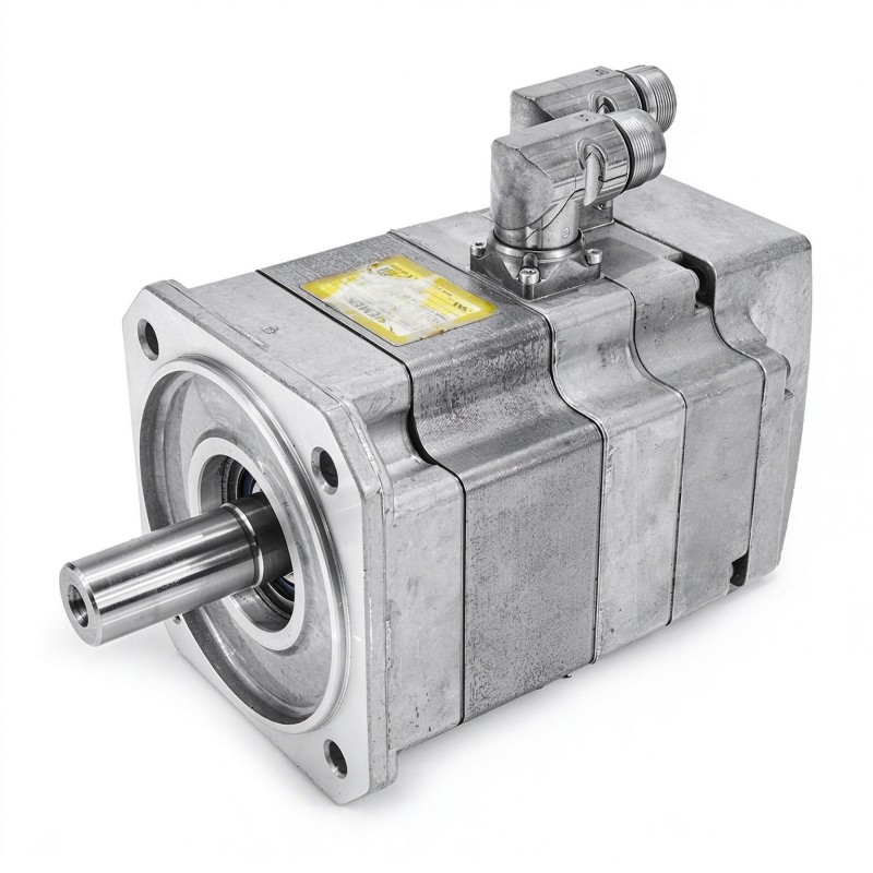
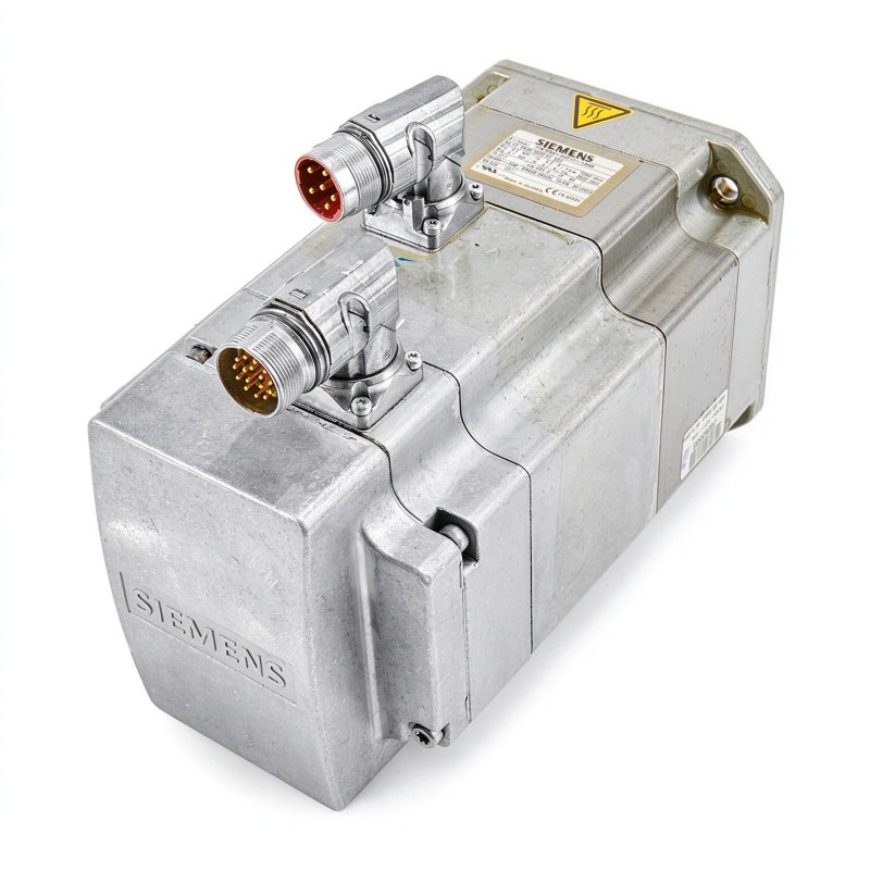
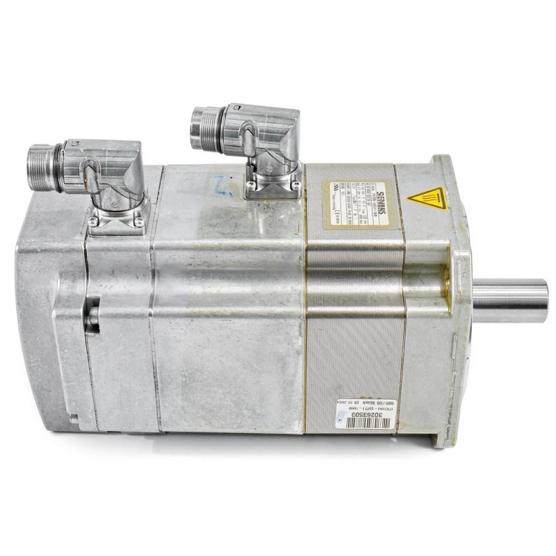
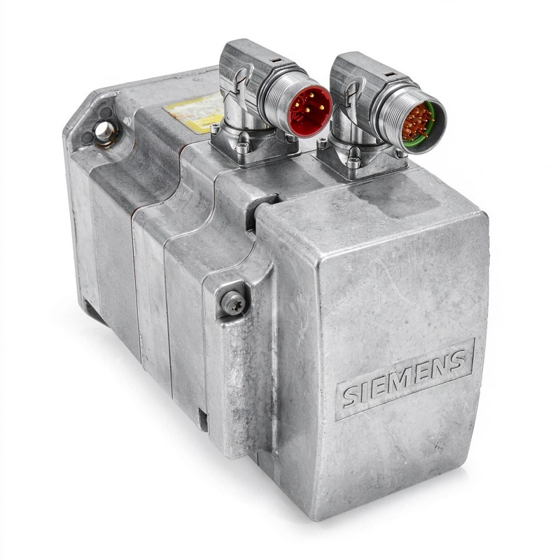
- Siemens
- 1FK7060-5AF71-1KH5
- Synchronous Servo Motor
- Germany
- 63 mm
- 8.302 kg
- Xiamen, China
- New & In Stock
- T/T, PayPal, Western Union
- 1 Year
- 1-3 Working Days
- DHL, UPS, TNT, FedEx and EMS.
- 24-Hour Service
- COO
- 5
Our advantage

Global Logistics
We have a 10-year logistics and express cooperation agreement, so our products can be shipped to any place in the world.

Brand new and original
Our products are imported in bulk from the place of origin. Because of the cooperative relationship, our products are all original and 100% new.

24-hour service
We provide 7*24 hours service to our customers. We will be there whenever you need us.

Price advantage
All our products are priced very favorably because we have our own warehouse and supply.
| Company Information | |||
| [email protected] | |||
| Mobile | +8615980777398 | ||
| +8615980777398 | |||
| 15980777398 |
Product Overview
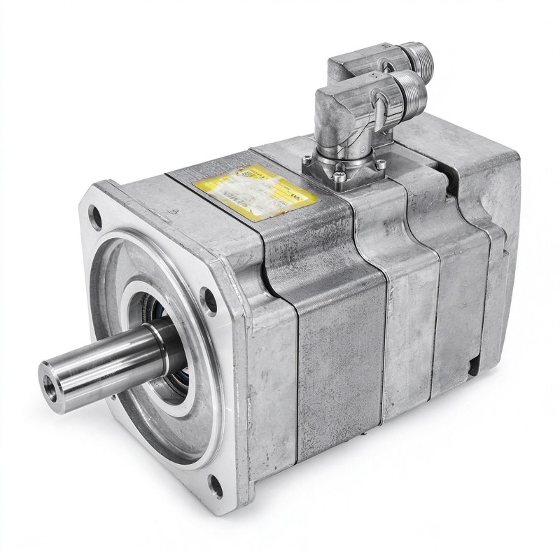
The Siemens 1FK7060-5AF71-1KH5 SIMOTICS S Synchronous Servo Motor is part of the 1FK7 Compact family of permanent-magnet synchronous motors. It serves as the rotary actuator in automated machinery where the position, speed, and acceleration of a mechanism must be controlled through a compatible servo drive. Typical installations include assembly machines, packaging equipment, indexing stations, and automated production lines.
In an assembly system, for example, the motor may move a fixture into a fastening station and hold its position while the operation takes place. In a packaging machine, it may drive a feed mechanism that must stop at repeatable intervals. These tasks require controlled acceleration and deceleration, accurate feedback, and sufficient torque to overcome the inertia and resistance of the connected mechanism.
The 1FK7060 frame belongs to the 63 mm shaft-height class. Its permanent-magnet rotor generates torque through interaction with the magnetic field produced by the stator windings. A compatible Siemens servo drive regulates the motor current and processes the motion feedback, allowing the machine controller to coordinate the axis with the wider production sequence.
The 1KH5 configuration is associated with a feedback-equipped motor and an integrated holding-brake arrangement. The feedback system supports position monitoring by the compatible drive, while the brake can secure the shaft when the motor is stationary and the brake is correctly engaged. This is useful for mechanisms that must remain in position during a controlled stop or when the drive is disabled. A holding brake is not intended to stop a freely rotating shaft under normal operating conditions.
The motor’s brake and feedback interfaces must be integrated into the drive configuration as part of the complete axis. Brake release, motor enable, and shutdown sequences need to be coordinated so that the brake is not used as a substitute for normal servo deceleration. Applications involving suspended or gravity-loaded mechanisms also require an assessment of the complete load-holding and machine-safety arrangement.
Mechanical installation has a direct effect on motion performance. Shaft alignment, coupling selection, mounting rigidity, and load inertia influence vibration, positioning accuracy, and bearing life. When replacing an installed motor, matching the complete Siemens order number is important because encoder technology, connector configuration, and brake characteristics can differ among otherwise similar 1FK7 motors.
Technical Specifications
| Parameter | Specification |
|---|---|
| Manufacturer | Siemens |
| Model | 1FK7060-5AF71-1KH5 |
| Product Type | SIMOTICS S Synchronous Servo Motor |
| Product Family | SIMOTICS S 1FK7 Compact |
| Motor Technology | Permanent-Magnet Synchronous Motor |
| Motor Frame | 1FK7060 |
| Rated Speed | 3,000 rpm |
| Rated Power | 1.48 kW |
| Rated Torque | 4.7 Nm |
| Static Torque at 100 K Temperature Rise | 6.0 Nm |
| Cooling Method | Natural Cooling |
| Mounting Arrangement | IM B5, IM V1, IM V3 |
| Feedback System | DRIVE-CLiQ-compatible absolute encoder configuration |
| Holding Brake | Integrated holding brake |
| Brake Function | Shaft holding at standstill |
| Drive Compatibility | Compatible Siemens servo drive selected for the motor and feedback configuration |
| Shaft Height | 63 mm |
| Weight | 8.302 kg |
Product Features
- Permanent-magnet synchronous design: Converts regulated electrical input into rotary torque for servo-controlled movement.
- 1FK7 Compact platform: Supports integration into industrial machinery using the corresponding motor mounting arrangement.
- 3,000 rpm rated operating speed: Supports applications requiring controlled rotary movement within the motor’s operating envelope.
- Feedback-based motion control: Allows a compatible drive to monitor motor position and regulate movement.
- Integrated holding brake: Helps retain the shaft at standstill when correctly engaged and used within its specified limits.
- Natural cooling: Dissipates motor heat through the specified cooling arrangement without a separate motor-mounted fan.
- Flange mounting: Supports installation in compatible machine structures and servo-axis assemblies.
- Drive-system integration: Works with compatible Siemens servo equipment for positioning and coordinated motion.
- Application-specific configuration: Supports selection within the 1FK7 family according to the axis’s electrical, mechanical, and control requirements.
Working Principle
The 1FK7060-5AF71-1KH5 generates rotary motion through the interaction between its permanent-magnet rotor and the magnetic field produced by the stator windings. A compatible servo drive regulates the winding current, controlling the torque available at the motor shaft.
Motion Command → Servo Drive → Stator Magnetic Field → Rotor Movement → Mechanical Load
When the machine controller requests a movement, the drive calculates the required response and supplies controlled current to the motor. During acceleration, the motor develops torque to overcome load resistance and rotational inertia. As the axis approaches its target, the drive adjusts the output to achieve the commanded speed or position.
Feedback allows the drive to monitor the motor’s movement. In a positioning application, this information supports the control loops that regulate the axis and correct deviations from the commanded motion. The encoder interface must be compatible with the selected drive so that position information can be processed correctly.
The integrated holding brake performs a separate function. When the motor is stationary and the brake is engaged, it applies holding force to resist shaft rotation. During normal motion, the brake must be released according to the required operating sequence. The servo drive, motor control, and brake control must be coordinated to avoid releasing the brake before sufficient motor torque is available or engaging it while the shaft is moving at an unsuitable speed.
Consider a machine axis that positions a fixture at a loading station. The servo drive moves the motor to the required position and brings the axis to a controlled stop. Once the appropriate standstill conditions are established, the brake can engage if the application requires the shaft to remain held. Before movement resumes, the control sequence releases the brake and restores normal servo operation.
The motor’s thermal behavior depends on the current required by the load and the duty cycle. Frequent acceleration, repeated reversals, and sustained torque can generate more heat than steady operation. Proper sizing therefore requires consideration of the actual motion profile, not just the rated speed or nominal power.
Role in a Siemens SIMOTICS S Servo Drive System
The 1FK7060-5AF71-1KH5 provides the mechanical output for a servo-controlled axis. The servo drive regulates its motion, the feedback system supplies position information, and the machine controller coordinates movement with other equipment. The integrated holding brake adds a shaft-holding function for suitable standstill conditions.
Machine Controller → SINAMICS Servo Drive → 1FK7060-5AF71-1KH5 → Mechanical Coupling → Machine Axis
| System Component | Function |
|---|---|
| Siemens 1FK7060-5AF71-1KH5 | Converts electrical input into controlled rotary movement |
| Compatible SINAMICS Servo Drive | Regulates motor current and executes motion-control functions |
| Machine Controller | Coordinates positioning commands with the production sequence |
| Motor Feedback System | Supplies position information to the compatible drive |
| Integrated Holding Brake | Holds the motor shaft at standstill within its specified operating limits |
| Motor Power Cable | Supplies electrical power from the drive |
| Feedback Connection | Carries the configured encoder communication |
| Brake Control Circuit | Coordinates brake release and engagement with the axis-control sequence |
| Mechanical Coupling | Transfers torque to the driven mechanism |
| Gearbox or Transmission | Adjusts output speed and torque where required |
| Machine Axis | Performs the required positioning or rotary movement |
The brake, feedback system, and servo drive must operate as a coordinated assembly. The brake’s holding function does not replace the drive’s motion control or the machine’s required safety measures.
Industrial Applications
| Application | Typical Use |
|---|---|
| Packaging Machinery | Driving indexing mechanisms and positioning packaging material between operations |
| Automated Assembly | Moving fixtures and tooling into repeatable working positions |
| Material Handling | Controlling transfer mechanisms that need defined stopping positions |
| Printing Equipment | Regulating feed mechanisms and synchronized rotary movement |
| Labeling Systems | Positioning products and feed mechanisms during labeling cycles |
| Machine Tools | Driving compatible feed or positioning axes |
| Inspection Equipment | Moving parts and fixtures into measurement positions |
| Automated Production Lines | Coordinating servo movement with sensors and machine-cycle timing |
| Vertical Positioning Mechanisms | Supporting controlled movement where a suitable holding arrangement is required |
| Special-Purpose Machinery | Operating application-specific axes that need servo control and standstill holding |
Applications with suspended loads, vertical movement, or potential movement after power loss require particular attention to the complete load-holding and safety arrangement. The integrated holding brake must be applied within its specified limits and should not be treated as a substitute for a separately required safety brake.
Installation and Maintenance
- Inspect the motor designation: Confirm that the installed unit matches the required 1FK7060-5AF71-1KH5 configuration and the machine’s electrical and mechanical interfaces.
- Check servo-drive compatibility: Ensure that the selected drive supports the motor’s rated data and feedback interface.
- Prepare the mounting flange: Clean the mating surfaces and inspect the mounting points for damage, contamination, or uneven contact.
- Align the mechanical coupling: Align the motor shaft with the driven mechanism within the coupling manufacturer’s permitted tolerances.
- Secure the motor assembly: Fasten the motor according to the applicable mounting procedure and ensure that the connection can withstand the operating loads.
- Connect the motor power cable: Inspect the connector, cable condition, protective grounding, and electrical connections before energizing the system.
- Connect the feedback interface: Establish the feedback connection and check communication status during drive commissioning.
- Integrate the holding brake: Connect the brake circuit and coordinate brake release and engagement with the motor-control sequence.
- Configure the servo drive: Set the appropriate motor and feedback parameters and confirm that the drive identifies the connected motor correctly.
- Test the axis under controlled conditions: Begin with a low-speed movement and check rotation direction, positioning response, brake operation, and drive diagnostics.
- Monitor operating conditions: Investigate abnormal heating, vibration, noise, or changes in positioning accuracy before returning the machine to normal production.
- Document maintenance results: Record the motor designation, drive configuration, brake test results, inspection findings, and corrective actions.
During maintenance, pay particular attention to brake behavior and feedback communication. If the motor moves unexpectedly during a stop or fails to release correctly, investigate the brake-control sequence, drive status, and mechanical load rather than assuming the motor itself is defective.
Related Components
| Component | Function |
|---|---|
| Siemens 1FK7060-5AF71-1KH5 | SIMOTICS S synchronous servo motor with feedback and holding-brake functions |
| Compatible SINAMICS Servo Drive | Controls motor current, speed, and positioning |
| SIMATIC Motion Controller | Coordinates servo movement with the machine sequence |
| Motor Power Cable | Supplies electrical power from the drive to the motor |
| DRIVE-CLiQ-Compatible Feedback Connection | Carries motor feedback information to compatible Siemens equipment |
| Brake Control Circuit | Coordinates brake release and engagement |
| Mechanical Shaft Coupling | Transfers motor torque to the connected mechanism |
| Precision Gearbox | Adjusts torque and speed for the driven axis |
| Motor Mounting Hardware | Secures the motor to the machine structure |
| Protective Grounding Connection | Provides the required protective electrical connection |
Recommended Related Models
| Model / Product Reference | Product Type | Typical Application |
|---|---|---|
| Siemens 1FK7060-5AF71-1KH5 | SIMOTICS S Synchronous Servo Motor | Servo-driven axis requiring the specified motor configuration and holding-brake function |
| Siemens 1FK7060-5AF71-1KH0 | SIMOTICS S 1FK7 Compact Servo Motor | Related motor configuration within the same frame and mounting family |
| Siemens 1FK7060-5AF71-1KG0 | SIMOTICS S 1FK7 Compact Servo Motor | Related motor variant without an integrated holding brake |
| Siemens 1FK7060-5AF71-1FB3 | SIMOTICS S 1FK7 Compact Servo Motor | Related motor configuration with a fitted-key shaft and holding brake |
| Siemens 1FK7060-5AF71-1EH0 | SIMOTICS S 1FK7 Compact Servo Motor | Related configuration with an absolute encoder using an EnDat interface and a holding brake |
| Siemens SINAMICS S120 | Servo Drive System | Servo control for compatible industrial positioning and coordinated-motion applications |
Key Advantages
- Supports controlled rotary motion in automated machinery.
- Combines permanent-magnet synchronous motor technology with feedback-based drive control.
- Includes a holding brake for suitable standstill applications.
- Integrates with compatible Siemens servo-drive equipment.
- Supports positioning and coordinated movement in industrial automation systems.
- Fits applications requiring a servo motor with an integrated shaft-holding function.
Technical FAQs
What is the purpose of the integrated holding brake on this servo motor?
The holding brake helps prevent shaft rotation when the motor is stationary and the brake is engaged. It is useful for applications that need the axis to remain in position during a controlled stop. It is not intended to replace normal servo deceleration or serve as a working brake for stopping a moving shaft.
How should brake operation be coordinated with servo movement?
The control sequence should establish sufficient motor torque before releasing the brake and should bring the axis to an appropriate standstill condition before engaging it. The brake-control logic must be coordinated with the servo drive and the machine sequence to avoid unintended movement or unnecessary mechanical stress.
What should be investigated if the motor runs but the positioning response is incorrect?
Check the encoder communication, drive configuration, mechanical coupling, load inertia, and motion-control parameters. Feedback errors and mechanical backlash can both affect positioning, so diagnosis should include the complete axis rather than focusing exclusively on the motor.
Is the holding brake sufficient to secure a vertical axis during a power failure?
The brake’s suitability depends on the load, required holding torque, operating conditions, and the machine’s safety design. Where uncontrolled movement could create a hazard, the complete system may require additional load-holding or safety measures. The motor’s holding brake should not automatically be treated as the sole protective measure.