

ProductPRODUCT
Featured products
Contact Us
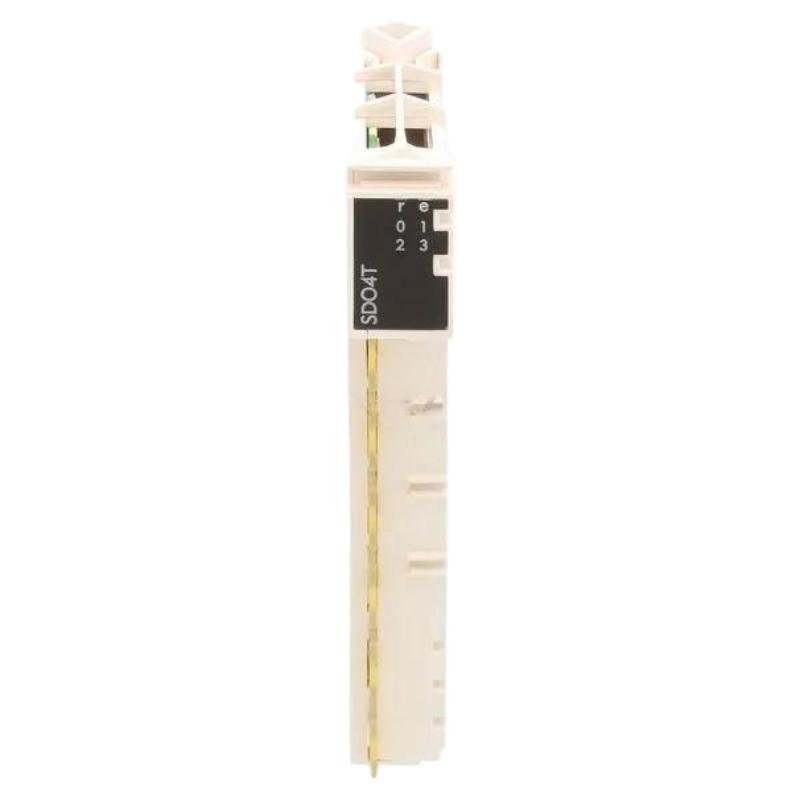
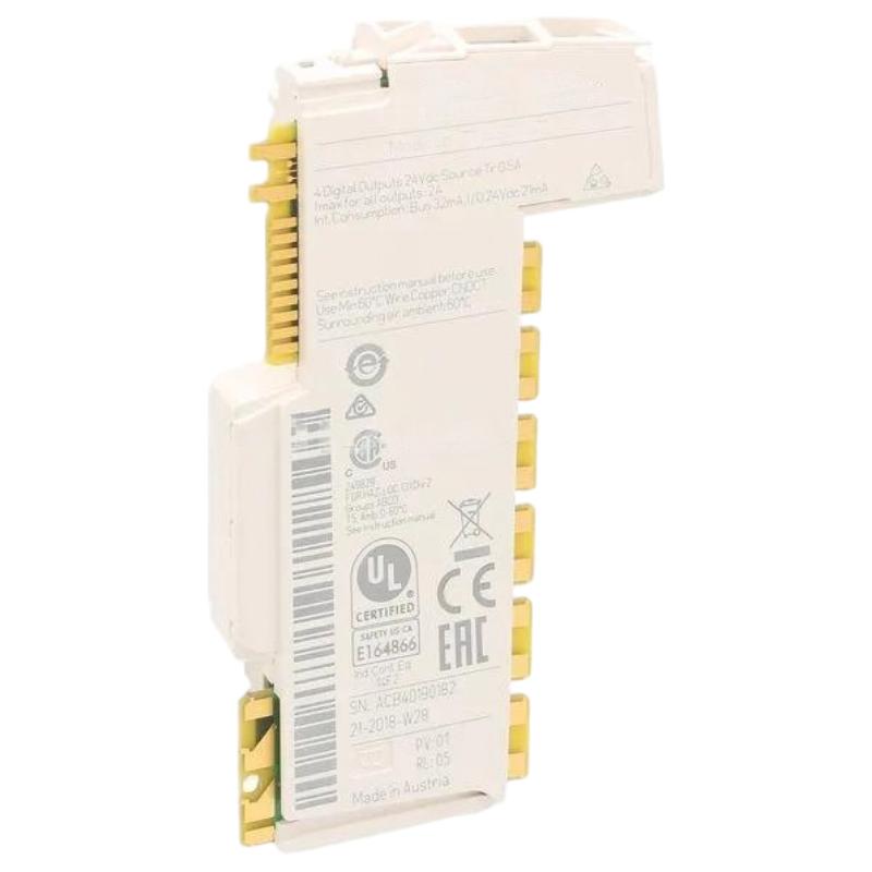
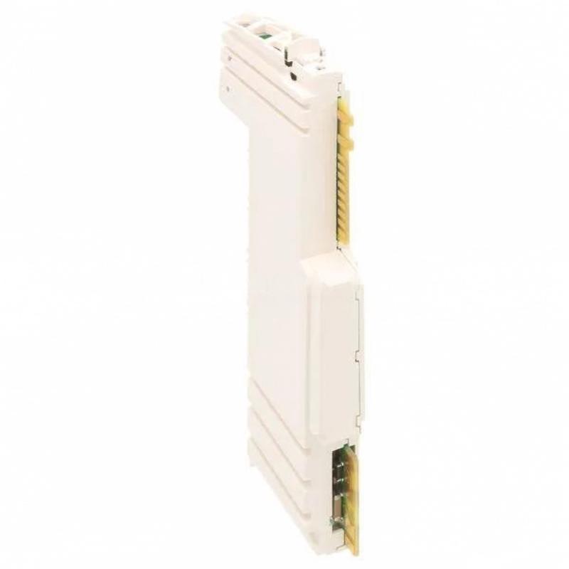
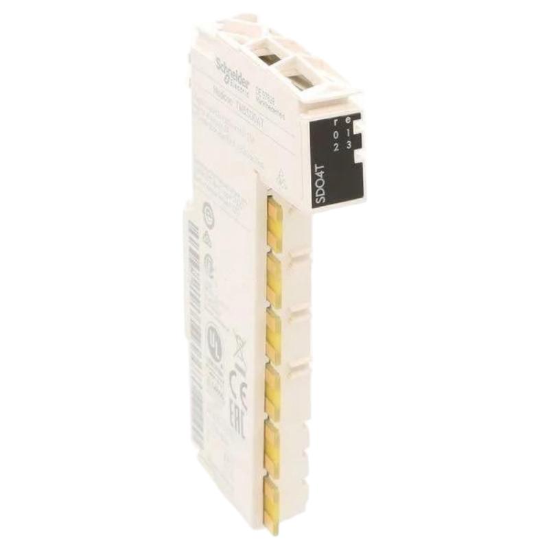
- Schneider
- TM5SDO4T
- Discrete Output Module
- France
- 99 × 12.5 × 75 mm
- 0.025 kg
- Xiamen, China
- New & In Stock
- T/T, PayPal, Western Union
- 1 Year
- 1-3 Working Days
- DHL, UPS, TNT, FedEx and EMS.
- 24-Hour Service
- COO
- 4
Our advantage

Global Logistics
We have a 10-year logistics and express cooperation agreement, so our products can be shipped to any place in the world.

Brand new and original
Our products are imported in bulk from the place of origin. Because of the cooperative relationship, our products are all original and 100% new.

24-hour service
We provide 7*24 hours service to our customers. We will be there whenever you need us.

Price advantage
All our products are priced very favorably because we have our own warehouse and supply.
| Company Information | |||
| [email protected] | |||
| Mobile | +8615980777398 | ||
| +8615980777398 | |||
| 15980777398 |
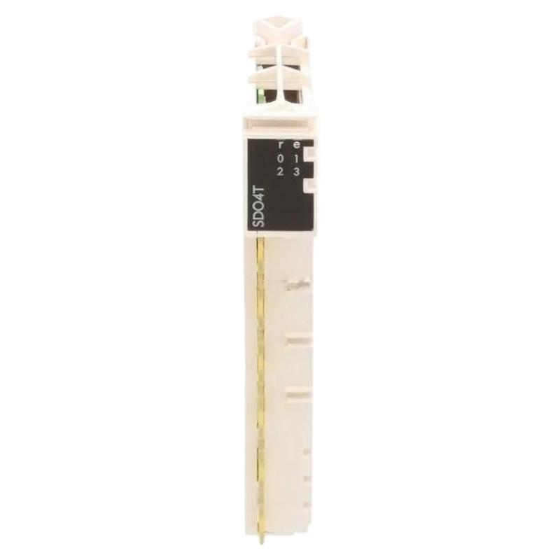
1. Product Overview
The Schneider TM5SDO4T Discrete Output Module is an industrial automation component designed for digital output functions in control systems. As part of the Schneider Electric Modicon TM5 automation platform, it is intended to support communication between a controller and external devices that require discrete control signals.
Discrete output modules are essential components in programmable logic controller (PLC) systems. They allow a controller to execute programmed commands and transmit output signals to connected field devices, helping automate equipment sequences, machine operations, and process control tasks.
The TM5SDO4T is suitable for applications where compact module dimensions and low component weight are important considerations. With listed dimensions of 99 × 12.5 × 75 mm and a weight of 0.025 kg, it can be considered for control cabinets and distributed machine-control installations where installation space is limited.
In an automation system, the controller determines when an output should change state according to its program, input conditions, and operating sequence. The discrete output module provides the hardware interface for translating the controller’s output command into an electrical signal suitable for the connected load, within the module’s specified operating limits.
Before integrating the TM5SDO4T into an existing installation, engineers should verify its exact electrical ratings, output configuration, wiring requirements, controller compatibility, and firmware or configuration requirements against the documentation for the specific hardware revision.
2. Technical Specifications
| Parameter | Specification |
|---|---|
| Brand | Schneider Electric |
| Model Number | TM5SDO4T |
| Product Type | Discrete Output Module |
| Automation Platform | Modicon TM5 series |
| Listed Dimensions | 99 × 12.5 × 75 mm |
| Listed Weight | 0.025 kg |
| Primary Function | Discrete output signal control |
| Typical System Role | Interface between a controller and external output devices |
| Installation Environment | Industrial automation control system |
| Electrical Output Details | Verify against the exact product documentation |
| Output Channel Configuration | Confirm from the applicable hardware specification |
| Rated Output Voltage and Current | Confirm before connecting field loads |
| Wiring and Terminal Requirements | Follow the specified wiring documentation |
| Environmental Ratings | Verify the permitted temperature, humidity, and installation conditions |
The dimensions and weight above are the supplied product data. Electrical ratings, channel characteristics, protection functions, and supported load types should be confirmed before the module is selected or commissioned.
3. Function and Working Principle
3.1 Discrete Output Signal Processing
A discrete output module is used to control devices that operate through defined electrical states rather than continuously variable signals. Depending on the application, these devices may include indicator lamps, interface relays, solenoid valves, and other compatible control loads.
The controller executes its application logic and determines the required output state. The TM5SDO4T then performs its assigned output function according to the system configuration and the module’s electrical characteristics.
A typical operating sequence includes:
- The PLC reads input signals from sensors, switches, or other system components.
- The application program evaluates the current process conditions.
- The controller determines the required discrete output state.
- The output module applies the corresponding signal to the configured output circuit.
- The connected device responds according to its electrical requirements and operating condition.
The actual output behavior depends on the module’s design, wiring arrangement, controller configuration, and connected load.
3.2 Interface Between the PLC and Field Devices
Industrial controllers often operate at a logic level that differs from the electrical requirements of field equipment. Output modules provide the interface between the controller’s commands and external circuits.
When a compatible field device is connected correctly, the output module allows the control program to operate that device as part of an automated sequence. This supports repeatable machine operation and reduces the need for separate manual switching during normal production.
The module’s permitted output voltage, current, switching characteristics, and load compatibility must be checked before use. A load that exceeds the specified electrical limits can cause unreliable operation or damage.
3.3 Integration with a Modular Automation Platform
Modular automation systems allow engineers to build a control configuration around the application’s input, output, communication, and processing requirements. The TM5SDO4T is intended for use within its supported Modicon TM5 configuration.
Correct integration requires more than physical installation. The module must be recognized by the controller, assigned correctly in the hardware configuration, and connected according to the prescribed system architecture.
The exact bus-base arrangement, terminal accessories, and configuration procedure should be confirmed for the installed TM5 hardware combination.
4. Role in Industrial Automation Systems
4.1 Machine Control
Discrete output modules are commonly used in automated machinery to execute commands generated by a PLC. Depending on the verified output characteristics and application design, an output may control a compatible indicator, relay interface, or other discrete device.
In packaging equipment, assembly machines, and material-handling systems, these outputs can form part of a programmed operating sequence. The controller coordinates output states with sensor feedback, timing conditions, and safety-related interlocks implemented by the overall system.
4.2 Process Automation
Industrial processes frequently rely on discrete commands to initiate or stop equipment functions. A discrete output module can support these commands where the connected device and circuit are compatible with the module’s electrical specifications.
Examples include operating interface relays, signaling machine status, and controlling suitable auxiliary devices. The output module should not be assumed to replace dedicated motor starters, protective devices, or safety-rated control equipment.
4.3 Control Cabinet Integration
Compact modules help system designers organize control hardware within a limited cabinet footprint. The listed dimensions of the TM5SDO4T may be useful when evaluating space requirements, mounting arrangements, wiring access, and service clearance.
Cabinet planning should also account for the complete assembly, including the compatible base, terminals, wiring ducts, cable bend radius, ventilation requirements, and access needed for maintenance.
4.4 Equipment Replacement and Maintenance
A discrete output module may need replacement when output faults, physical damage, or other confirmed hardware problems affect system operation. Before installing a replacement, maintenance personnel should confirm the complete model number and hardware revision, along with compatibility with the existing controller and TM5 configuration.
Replacing a module solely because it has similar dimensions or a similar model name is not sufficient. Electrical characteristics and system compatibility must also match.
5. Industrial Applications
The Schneider TM5SDO4T may be evaluated for industrial automation applications that require discrete output control within a compatible Modicon TM5 system.
Packaging and Production Machinery
Packaging equipment relies on coordinated commands to operate different machine functions. Discrete outputs can be incorporated into sequences involving compatible actuators, relay interfaces, and status indicators.
Assembly and Material Handling
Automated assembly lines and material-handling systems use controller outputs to coordinate equipment actions. Output states may be linked to sensor feedback, machine status, and programmed sequence conditions.
Process Equipment
In process-related installations, discrete output signals can support auxiliary control functions, equipment status signaling, and other suitable on/off operations. The connected load must remain within the module’s verified operating limits.
OEM Machinery
Original equipment manufacturers may use modular PLC systems to standardize control cabinet designs across different machine models. A compact output module can be considered when designing a supported TM5 configuration, provided that its channel count and electrical characteristics satisfy the application.
Industrial Test and Inspection Systems
Automated test equipment may require discrete commands to activate compatible fixtures, indicators, or interface devices. The output module can be included as part of the control architecture where its response characteristics and electrical ratings meet the application’s requirements.
These applications are examples of potential use cases for a discrete output module. Final suitability depends on the verified specifications of the TM5SDO4T and the requirements of the equipment.
6. Installation and System Integration
Correct installation is essential for reliable output operation. The module should be installed by qualified personnel familiar with industrial control systems and the relevant electrical safety requirements.
6.1 Verify the Model and System Configuration
Before installation, confirm the product label and complete model number. Check that the module is supported by the intended controller, base arrangement, and system configuration.
Review the applicable documentation for:
- Compatible TM5 system components.
- Output channel configuration and electrical characteristics.
- Terminal assignments and wiring requirements.
- Controller configuration and firmware requirements.
- Environmental and mounting limitations.
Do not assume that modules in the same product family share identical output characteristics.
6.2 Isolate Power Before Installation
Before handling the module or changing its wiring, follow the site’s lockout/tagout procedures and isolate all relevant power sources. Verify that the circuit is de-energized using an appropriate method.
Disconnecting the main supply alone may not remove every hazardous voltage. External field circuits and separately powered devices must also be considered.
Never insert, remove, or rewire the module under power unless the exact system documentation explicitly permits the operation and the applicable safety procedures are followed.
6.3 Inspect the Module and Mounting Components
Examine the module housing, contacts, connectors, and compatible mounting components for visible damage or contamination. Confirm that the required base and terminal accessories are present and correctly identified.
Do not install a module with damaged connectors, bent contacts, cracked housing, or evidence of overheating.
6.4 Install According to the Prescribed Arrangement
Mount the module in the supported TM5 arrangement and ensure that it is properly seated and secured. Follow the manufacturer’s instructions for mechanical installation and connection to the system bus.
Avoid excessive force during installation. Incorrect alignment can damage connectors or prevent reliable electrical contact.
6.5 Connect the Field Wiring
Use the correct wiring diagram and terminal assignments for the exact module. Confirm the supply arrangement, polarity where applicable, load requirements, and any required external protective devices.
Separate signal wiring from sources of significant electrical interference where appropriate. Use suitable wire sizes, terminal preparation, and cable routing practices for the installation.
Never determine terminal functions from physical appearance alone.
6.6 Configure the Controller
After the hardware is installed, use the applicable engineering software to configure the system as required. Confirm that the controller recognizes the module and that the output addresses correspond to the intended program logic.
Review the controller’s diagnostic information before enabling normal operation. If the module is not recognized, investigate configuration, bus connection, power, and hardware compatibility before attempting to operate connected loads.
6.7 Perform Functional Testing
After installation and configuration, carry out a controlled commissioning test.
- Confirm that wiring and protective measures have been checked.
- Verify that the controller reports the expected hardware status.
- Test each required output using an approved commissioning procedure.
- Confirm that the corresponding field device responds correctly.
- Check for unexpected activation, intermittent operation, or diagnostic errors.
- Record the final configuration and commissioning results.
Where an output controls equipment capable of causing injury or damage, test it under controlled conditions with the required safeguards in place.
7. Troubleshooting Common Problems
Output problems can result from module faults, configuration errors, incorrect wiring, power-supply issues, load failures, or problems elsewhere in the control system. Troubleshooting should begin with the least invasive checks.
Problem 1: The Module Is Not Recognized by the Controller
Possible causes:
- Incorrect hardware configuration.
- Incompatible system components.
- An improperly seated module or base connection.
- A power or system-bus problem.
- A damaged connector or module.
Recommended checks:
- Review controller diagnostics and the configured hardware list.
- Verify that the exact model is supported by the installed system.
- Isolate power and inspect the module’s physical connections.
- Check the system power and bus arrangement against the applicable documentation.
- Restore power and repeat the recognition test using the approved procedure.
If the module remains unrecognized after configuration and connection checks, test with a known-compatible component only when the replacement procedure permits it.
Problem 2: An Output Does Not Activate
Possible causes:
- The PLC program has not commanded the output.
- The output address is assigned incorrectly.
- Field wiring is open or connected to the wrong terminal.
- The connected device is faulty.
- The load exceeds the module’s permitted ratings.
- The module has detected a fault or has been damaged.
Recommended checks:
- Confirm the output command and associated program conditions.
- Verify the configured output address.
- Inspect the wiring against the correct terminal diagram.
- Check the external supply and connected load using safe procedures.
- Review controller and module diagnostics.
- Compare the load requirements with the verified output ratings.
Do not conclude that the module is defective until the program, wiring, supply, and load have been checked.
Problem 3: The Output Operates Intermittently
Possible causes:
- Loose or poorly prepared wiring.
- An unstable external supply.
- Electrical interference.
- An intermittent field device.
- Incorrect system configuration.
- A damaged connection or module.
Recommended checks:
Inspect terminal connections with the system safely isolated, review supply stability, and check whether the problem occurs in conjunction with a particular machine operation. Where electrical noise is suspected, review grounding, cable routing, and separation between control and power wiring.
Problem 4: The Connected Device Does Not Respond Correctly
An output may change state correctly while the field device still fails to operate as expected.
Possible causes:
- Incorrect load voltage or current requirements.
- Incorrect wiring polarity where applicable.
- A faulty relay, solenoid, or other field device.
- A mechanical obstruction or process interlock.
- An incorrect output command or sequence.
Check the electrical circuit and field device independently using approved test methods. Verify the load’s specifications before reconnecting it to the output module.
Problem 5: Controller Diagnostics Report an Error
Diagnostic messages may indicate a configuration problem, system-bus issue, power problem, or hardware fault.
Record the complete diagnostic message and identify when it appears. Compare the message with the documentation for the actual controller and module revision. Correct the underlying issue before clearing the diagnostic or returning the machine to service.
Problem 6: The Replacement Module Does Not Operate as Expected
A replacement may have a similar appearance but differ in electrical characteristics, configuration requirements, or hardware compatibility.
Confirm the complete part number, the required base and terminal arrangement, controller support, output addressing, and wiring. If the original configuration was modified during replacement, restore the verified settings before conducting another functional test.
8. Compatible System Components
The TM5SDO4T should be used only with components supported by the specific Modicon TM5 system configuration.
| Component Category | Role in the System | Verification Required |
|---|---|---|
| Compatible TM5 Controller | Executes application logic and manages I/O | Confirm model support and firmware requirements |
| Compatible TM5 Base or Connection Component | Provides the required mechanical and electrical interface | Verify the exact module and base combination |
| System Power Supply | Supplies power to the relevant system circuits | Confirm voltage, capacity, and wiring arrangement |
| Terminal and Wiring Accessories | Connect field circuits to the module | Verify terminal assignments and accessory compatibility |
| Field Devices | Receive discrete control signals | Confirm load voltage, current, and switching requirements |
| Engineering Software | Supports hardware configuration and diagnostics | Confirm support for the installed controller and hardware |
| External Protection and Interface Devices | Protect or interface with field circuits where required | Select according to the circuit design and applicable ratings |
This table describes component categories rather than a guaranteed compatibility list. Exact part numbers should be selected from the technical documentation for the installed system.
9. Replacement and Alternative Selection
When selecting a replacement for the Schneider TM5SDO4T, compare the full technical specification rather than relying on product-family similarity alone.
| Selection Factor | What to Verify |
|---|---|
| Model Identification | Exact part number and hardware revision |
| Output Function | Required discrete output behavior |
| Channel Configuration | Number and arrangement of output channels |
| Electrical Characteristics | Rated voltage, current, and supported load types |
| System Compatibility | Controller, base, bus, and configuration support |
| Wiring Arrangement | Terminal layout and required accessories |
| Physical Dimensions | Available mounting space and installation clearance |
| Environmental Conditions | Permitted temperature and operating environment |
| Availability | Stock condition, lead time, and product lifecycle status |
Potential replacement categories include an identical TM5SDO4T module with a verified matching revision or another output module explicitly approved for the same application and hardware configuration.
A substitute should not be installed solely because it fits in the same space. Differences in output technology, terminal assignments, current capacity, protection features, or software configuration may prevent direct replacement.
10. Key Advantages
Compact Physical Design
The listed dimensions of 99 × 12.5 × 75 mm make the TM5SDO4T relevant to installations where control-system space is limited. Actual space planning should include all required mounting and wiring clearances.
Low Listed Weight
At a listed weight of 0.025 kg, the module is lightweight within the overall control-system assembly. Weight alone, however, does not determine its electrical or functional suitability.
Discrete Control Integration
The module’s intended output role supports the integration of digital control commands into a compatible industrial automation system.
Modular System Architecture
A modular platform allows control-system designers to organize the required components according to the application. This can simplify system planning and component-level maintenance when the hardware is configured correctly.
Support for Automated Sequences
Discrete outputs are a fundamental part of automated machine sequences. They allow programmed control actions to be transmitted to compatible external devices as part of a coordinated process.
Service and Replacement Planning
Clear model identification and verification of electrical characteristics help maintenance teams reduce the risk of installing an incompatible replacement.
11. Technical FAQs
Q1. What is the Schneider TM5SDO4T?
The Schneider TM5SDO4T is identified as a discrete output module associated with the Modicon TM5 automation platform. Its role is to provide discrete output functions within a compatible control-system configuration.
Q2. What are the dimensions and weight of the TM5SDO4T?
The supplied product data lists dimensions of 99 × 12.5 × 75 mm and a weight of 0.025 kg.
Q3. What is the primary function of a discrete output module?
A discrete output module allows a controller to issue on/off-style commands to compatible external circuits. The supported loads and electrical limits depend on the exact module specification.
Q4. Can the TM5SDO4T control a solenoid valve?
It may be considered for a compatible application if the valve circuit meets the module’s verified electrical ratings and wiring requirements. Check whether the load requires an external interface device or additional protection before connecting it.
Q5. Can the TM5SDO4T be installed in any Schneider Electric PLC system?
No. Physical fit or brand identity does not establish compatibility. The controller, base arrangement, system bus, configuration software, and hardware revision must all be supported.
Q6. Why might an output fail to activate?
Possible causes include incorrect program logic, an incorrect output address, wiring errors, missing external power, a faulty field device, or a module fault. A structured diagnostic process should check each possibility.
Q7. What should be checked before replacing the module?
Confirm the exact model number, hardware revision, system compatibility, terminal arrangement, electrical ratings, and configuration requirements. Follow the applicable isolation and replacement procedures.
Q8. Does the TM5SDO4T support every type of industrial load?
This should not be assumed. Verify the permitted load types, switching characteristics, output voltage, current limits, and protection requirements using the specification for the exact module.
Q9. Is the TM5SDO4T suitable for a new automation project?
It can be evaluated when a project requires a compatible discrete output module within a supported TM5 architecture. Engineers should also confirm availability, lifecycle status, required output capacity, and long-term maintenance needs before finalizing the design.
Q10. How can reliable operation be maintained?
Use the specified installation and wiring procedures, operate within the verified electrical limits, keep the control cabinet within its permitted environmental conditions, review diagnostic messages, and document any hardware or configuration changes.
12. Conclusion
The Schneider TM5SDO4T Discrete Output Module is a compact industrial automation component intended to provide discrete output functionality within a compatible Modicon TM5 control system. Its listed dimensions of 99 × 12.5 × 75 mm and weight of 0.025 kg are useful reference points for component identification and control cabinet planning.
For reliable operation, engineers and maintenance personnel should verify the module’s electrical characteristics, channel configuration, controller compatibility, wiring requirements, and environmental limitations before installation. Proper commissioning and systematic troubleshooting can help identify whether an output problem originates in the controller program, configuration, field wiring, connected equipment, or module hardware.
When purchasing or replacing the TM5SDO4T, always match the complete part number and confirm compatibility with the existing automation system. This approach supports safer installation, more dependable operation, and more effective maintenance planning in industrial control applications.