

ProductPRODUCT
Featured products
Contact Us
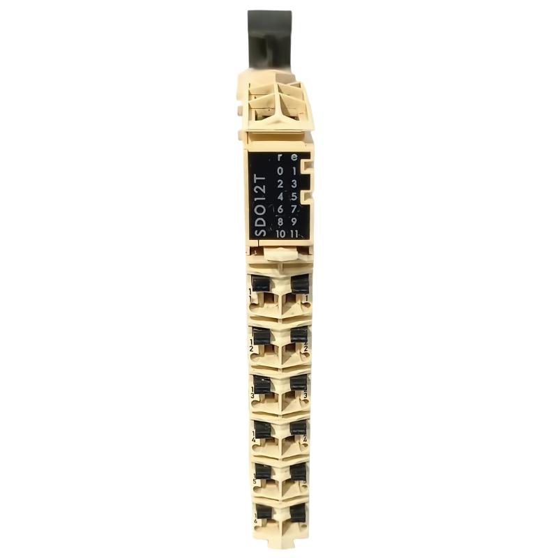
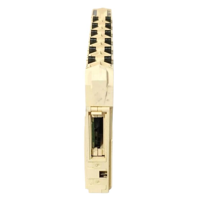
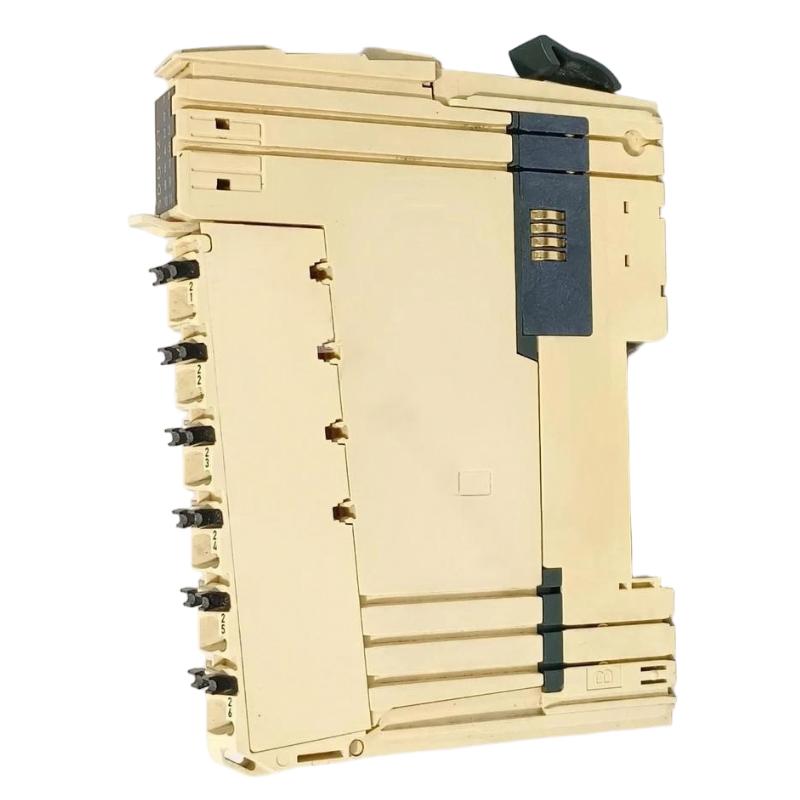
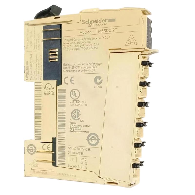
- Schneider
- TM5SDO12T
- Discrete Output Module
- France
- 99 × 12.5 × 75 mm
- 0.025 kg
- Xiamen, China
- New & In Stock
- T/T, PayPal, Western Union
- 1 Year
- 1-3 Working Days
- DHL, UPS, TNT, FedEx and EMS.
- 24-Hour Service
- COO
- 4
Our advantage

Global Logistics
We have a 10-year logistics and express cooperation agreement, so our products can be shipped to any place in the world.

Brand new and original
Our products are imported in bulk from the place of origin. Because of the cooperative relationship, our products are all original and 100% new.

24-hour service
We provide 7*24 hours service to our customers. We will be there whenever you need us.

Price advantage
All our products are priced very favorably because we have our own warehouse and supply.
| Company Information | |||
| [email protected] | |||
| Mobile | +8615980777398 | ||
| +8615980777398 | |||
| 15980777398 |
1. Product Overview
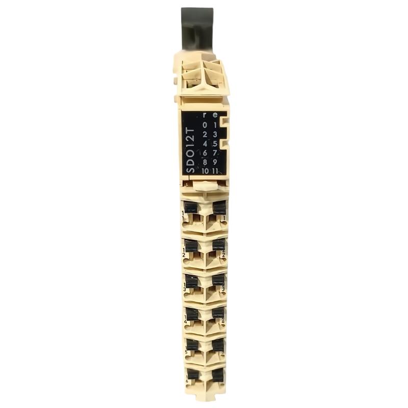
The Schneider TM5SDO12T Discrete Output Module is an industrial automation component intended for discrete output applications within a compatible control system. Discrete output modules enable a programmable logic controller (PLC) to send switching commands to field devices, supporting automated machine sequences, equipment control, and process operations.
In industrial automation, output signals connect programmed control logic with physical actions. Depending on the module’s documented electrical characteristics and the connected interface equipment, discrete outputs may be used in applications involving indicator devices, relays, solenoid valves, and other compatible control loads.
The Schneider TM5SDO12T is listed with dimensions of 99 × 12.5 × 75 mm and a weight of 0.025 kg. Its compact form factor can be beneficial in modular control cabinets where efficient use of mounting space is important.
When purchasing this module for a new installation or as a replacement part, it is important to verify the complete model number, supported controller platform, output-channel configuration, electrical ratings, and compatible mounting or bus-base arrangement. These details determine whether the module is suitable for the intended application.
2. Technical Specifications
| Parameter | Specification |
|---|---|
| Brand | Schneider Electric |
| Model Number | TM5SDO12T |
| Product Type | Discrete Output Module |
| Automation Platform | Verify the supported platform in the product documentation |
| Dimensions | 99 × 12.5 × 75 mm |
| Weight | 0.025 kg |
| Primary Function | Discrete output signal control |
| Typical System Role | PLC-controlled switching and field-device command interface |
| Installation Environment | Approved industrial control cabinet or equipment enclosure |
| Output Channel Configuration | Verify the exact product documentation |
| Output Voltage and Current Ratings | Verify the exact product documentation |
| Output Circuit Type | Confirm from the manufacturer specifications |
| System Compatibility | Verify controller, bus base, and module configuration |
Note: Dimensions and weight are based on the supplied product information. Specific electrical ratings, output-channel details, connection assignments, and supported hardware combinations should be confirmed for the exact TM5SDO12T version.
3. Function and Working Principle
A discrete output module receives control commands from an automation controller and uses its output circuitry to switch compatible electrical signals. These signals allow a PLC program to control external devices and coordinate machine operations.
The exact output technology and electrical limits of the TM5SDO12T must be confirmed from its technical documentation. Load compatibility should never be assumed from the product name alone.
3.1 Output Command Processing
During normal operation, the PLC executes its control program and determines the required output states. The corresponding commands are transferred through the supported automation architecture to the output module.
The module then changes the relevant output state according to the controller command and the module’s operating characteristics. This enables the control system to initiate or stop supported equipment actions.
3.2 Interface with Field Devices
Discrete output modules are commonly used to command devices that operate in distinct states. Depending on electrical compatibility, typical applications can include:
- Indicator lamps and status lights.
- Relay or contactor interface circuits.
- Compatible solenoid valves.
- Machine control signals.
- Other supported discrete switching loads.
Before connecting a device, confirm the output type, rated voltage, current limits, switching characteristics, and any required protective components.
3.3 Integration with PLC Logic
Output commands often form part of a larger machine sequence. For example, a PLC may issue an output command after receiving a sensor signal and confirming that the required interlocks are satisfied.
The output module provides the hardware interface between the programmed command and the corresponding field circuit. Correct configuration and wiring are essential to ensure that the intended device responds to the correct PLC output.
4. Role in Industrial Automation Systems
4.1 Automated Machine Control
Discrete output modules support control functions in manufacturing equipment, packaging machines, assembly systems, and other automated machinery. They allow the PLC to issue commands to compatible devices as part of a defined operating sequence.
4.2 Equipment Switching and Status Functions
Many industrial systems rely on discrete commands to activate indicators, operate interface relays, or control compatible actuators. A properly configured output module helps connect these commands to the required field circuits.
4.3 Production Line Coordination
Production lines often consist of multiple machines and stations that must operate in a coordinated sequence. Discrete output signals can be used to initiate machine actions, control material-handling steps, and coordinate equipment when the system design supports these functions.
4.4 Control Cabinet Maintenance
When an output channel stops responding, the fault may originate from the module, the controller configuration, the field wiring, the connected load, or the external power supply. Correctly identifying the TM5SDO12T and understanding its position in the control architecture can help technicians conduct systematic troubleshooting.
5. Industrial Applications
The Schneider TM5SDO12T may be considered for applications requiring a compatible discrete output interface, subject to verification of the model’s specifications and supported system configuration.
Typical industrial environments for discrete output technology include:
- Manufacturing machinery: Sending switching commands to compatible equipment interfaces.
- Packaging systems: Coordinating machine actions and production sequences.
- Material handling: Controlling supported devices within conveyor and transfer systems.
- Assembly equipment: Issuing discrete commands during automated assembly cycles.
- Industrial control panels: Providing output interfaces within a compatible PLC architecture.
- OEM machinery: Supporting machine-control functions in approved modular configurations.
- Maintenance and spare-parts management: Replacing an existing module when the exact model has been verified.
These examples describe general applications for discrete output modules. The suitability of the TM5SDO12T for a particular device depends on its documented electrical capabilities and system compatibility.
6. Installation and System Integration
Proper installation helps ensure reliable output operation and protects connected equipment. The following procedure provides general guidance. Always follow the manufacturer’s instructions for the specific module and installation.
Step 1: Verify the Product Identification
Check the product label to confirm the model number TM5SDO12T. Compare it with the existing component and the equipment’s approved parts list.
Do not substitute a visually similar module without confirming its output configuration and compatibility.
Step 2: Isolate the Equipment
Before handling the module or its wiring, follow the site’s lockout/tagout procedures and isolate all relevant energy sources. Confirm that the equipment is in a safe condition for maintenance.
Step 3: Confirm Hardware Compatibility
Verify the supported controller platform, bus base, neighboring modules, and system architecture. Check whether any configuration or firmware requirements apply to the intended installation.
Step 4: Inspect the Module and Mounting Arrangement
Check the housing, contacts, mounting features, and connectors for damage or contamination. Inspect the surrounding assembly for loose connections or signs of overheating.
Do not install a damaged component or force it into position.
Step 5: Verify Output Wiring
Consult the manufacturer’s terminal diagram and the approved electrical drawings. Confirm the correct terminal assignments, supply arrangement, polarity where applicable, and load requirements.
Ensure that the connected devices are compatible with the module’s specified output voltage, current, and switching characteristics. Do not assume that every type of actuator or load can be driven directly by the module.
Step 6: Install the Module
Install the component using the prescribed mounting and connection procedure. Make sure that it is correctly seated and that the required interconnections are secure.
Do not improvise terminal arrangements or use unapproved modifications to adapt the module to another system.
Step 7: Check the Controller Configuration
Review the PLC hardware configuration and output mapping. Confirm that the relevant output addresses correspond to the intended field devices and that the control program is configured for the installed hardware.
Step 8: Commission the Output Circuit
After completing the installation checks, restore power according to the approved commissioning procedure. Test the output under controlled conditions and monitor the relevant controller diagnostics.
Before testing machinery, confirm that unexpected movement or process activation cannot create a hazard. Verify the actual field-device response instead of relying only on the PLC command status.
7. Troubleshooting Common Problems
Output-related faults can arise from several parts of an automation system. A structured diagnostic process helps distinguish module problems from wiring, configuration, power, and load issues.
Problem 1: Output Does Not Activate
Possible causes:
- The PLC program is not issuing the expected command.
- The output address or hardware configuration is incorrect.
- The field circuit has no supply.
- The connected load is incompatible or defective.
- Wiring or terminal connections are incorrect.
- The output channel or module has developed a fault.
Recommended troubleshooting steps:
- Check the relevant PLC logic and commanded output state.
- Verify the I/O address mapping and module configuration.
- Inspect the field circuit against the approved wiring diagram.
- Confirm that the connected load and power supply meet the module specifications.
- Review controller and module diagnostic information.
- Isolate power before changing wiring or replacing hardware.
Problem 2: Output Activates Intermittently
Possible causes:
- Loose terminals or damaged wiring.
- Unstable field power.
- Electrical interference.
- A failing connected load.
- A problem in the controller program or interlock logic.
- An intermittent module or interconnection fault.
Recommended troubleshooting steps:
Inspect wiring and terminals with the system safely isolated. Review fault logs and PLC status information to determine whether the command itself is intermittent or whether the problem occurs downstream in the field circuit.
If electrical interference is suspected, review grounding, cable separation, shielding, and routing according to the equipment’s installation requirements.
Problem 3: Output Is Indicated as Active but the Device Does Not Respond
Possible causes:
- Incorrect field wiring.
- A missing external supply.
- A defective relay, actuator, or other connected device.
- An open circuit or failed connection.
- A mismatch between the load and the module’s output characteristics.
Recommended troubleshooting steps:
Confirm that the PLC command is correct, then inspect the external circuit and connected load. Use appropriately rated test equipment and follow the site’s electrical safety procedures. Do not assume that an active software status proves the field device is receiving the correct electrical signal.
Problem 4: Controller Does Not Recognize the Module
Possible causes:
- Unsupported hardware configuration.
- Incorrect module installation.
- A damaged bus base or interconnection.
- Power or communication problems elsewhere in the assembly.
- Incorrect controller configuration.
Recommended troubleshooting steps:
Verify the model number and supported module combination. Check the physical assembly with power isolated, then review the controller’s hardware diagnostics and configuration settings.
Problem 5: The Fault Persists After Replacement
Replacing the output module may not resolve a problem caused by the field device, wiring, external supply, PLC logic, or another component.
Before replacing additional parts, compare the original and replacement configurations, verify the output mapping, inspect the load circuit, and review system diagnostics. A documented troubleshooting process helps prevent repeated failures and unnecessary downtime.
8. Compatible System Components
The TM5SDO12T must be integrated with the appropriate controller, mounting arrangement, field circuits, and associated hardware. The following table lists general component categories that may be relevant to a compatible system.
| Component Category | Function | Verification Required |
|---|---|---|
| PLC or automation controller | Executes logic and issues output commands | Confirm supported platform |
| Compatible bus base | Provides the required mounting and interconnection arrangement | Verify the exact supported model |
| System power supply | Provides power to applicable automation hardware | Confirm voltage and capacity requirements |
| Field power supply | Supplies compatible external loads where required | Verify circuit design and electrical ratings |
| Relays and contactors | Provide switching or interface functions | Confirm coil and interface compatibility |
| Solenoid valves and actuators | Convert electrical commands into physical actions | Verify load and output compatibility |
| Terminal blocks and wiring | Connect output circuits to field devices | Follow the approved wiring diagram |
| Engineering software | Configures and diagnoses the PLC hardware | Confirm supported software and hardware versions |
This is a general integration guide rather than a verified compatibility list. Always consult the exact product documentation before selecting associated components.
9. Replacement and Alternative Selection
When sourcing a replacement for the Schneider TM5SDO12T, matching the model number and electrical function is essential. A substitute with a similar size may have different output characteristics or require a different system configuration.
| Selection Criterion | What to Verify |
|---|---|
| Exact model number | Confirm TM5SDO12T against equipment records |
| Product function | Ensure that a discrete output module is required |
| Physical dimensions | Compare the supplied dimensions of 99 × 12.5 × 75 mm |
| Weight | Confirm the listed weight of 0.025 kg where relevant |
| Output configuration | Verify channel arrangement and output technology |
| Electrical ratings | Check voltage, current, and switching limitations |
| Load compatibility | Confirm suitability for the intended field device |
| Hardware compatibility | Verify controller, bus base, and module configuration |
| Product condition | Confirm whether the unit is new, refurbished, or used |
| Traceability | Check labeling, model identification, and supplied documentation |
Do not assume that another discrete output module is a direct replacement. Any alternative should be validated against the original module’s electrical characteristics, system requirements, and approved hardware configuration.
10. Key Advantages
When correctly specified and installed, a compatible discrete output module can provide several benefits for industrial control applications:
- PLC-to-field-device interfacing: Transfers discrete control commands to compatible external circuits.
- Modular automation integration: Supports structured I/O organization in an approved control architecture.
- Compact physical design: The supplied dimensions may help with space-conscious installations.
- Lightweight construction: The listed weight of 0.025 kg supports easy handling during maintenance.
- Simplified diagnostics: PLC status information and system diagnostics can help technicians trace output faults.
- Maintenance efficiency: Exact model identification supports more accurate spare-parts procurement.
- Application flexibility: Discrete output technology is widely used in machine control, production equipment, and industrial automation.
Actual benefits depend on the module’s documented specifications, correct system configuration, and suitable installation practices.
11. Technical FAQs
What is the Schneider TM5SDO12T?
The Schneider TM5SDO12T is identified as a discrete output module for industrial automation applications. Its precise output configuration and electrical characteristics should be confirmed from the documentation for the exact model.
What are the dimensions of the TM5SDO12T?
The supplied dimensions are 99 × 12.5 × 75 mm.
What is the weight of this module?
The supplied product weight is 0.025 kg.
What does a discrete output module do?
A discrete output module allows a PLC to issue switching commands to compatible field circuits. These commands may control indicators, interface relays, actuators, or other supported devices.
Can the TM5SDO12T directly drive any actuator?
No. The actuator or load must be compatible with the module’s documented output type, voltage, current, and switching characteristics. Some applications may require an external relay or interface device.
Can I use this module with any Schneider Electric PLC?
No. Compatibility depends on the supported controller platform, bus base, module arrangement, and system configuration. Verify the exact combination before installation.
Why is the output command active but the connected device does not work?
Possible causes include incorrect wiring, missing field power, an incompatible or defective load, or a fault in the output circuit. Check the controller status and the complete field circuit systematically.
What should I check before ordering a replacement?
Confirm the complete model number, output configuration, electrical ratings, system compatibility, physical dimensions, and product condition. Accurate identification helps reduce the risk of purchasing an unsuitable component.
12. Conclusion
The Schneider TM5SDO12T Discrete Output Module is an industrial automation component identified for discrete output applications within a compatible PLC-based control system. With supplied dimensions of 99 × 12.5 × 75 mm and a weight of 0.025 kg, it can be identified for purchasing, maintenance planning, and replacement-part inventory.
Before installing or ordering the module, verify the output-channel configuration, electrical ratings, controller compatibility, and supported mounting arrangement. Correct wiring, careful commissioning, and systematic troubleshooting help maintain dependable control-system operation and reduce avoidable equipment downtime.