
NewsNEWCENTER
Featured products

Contact Us
Schneider 140ACO02000 Analog Output Module Troubleshooting Guide
2026-10-14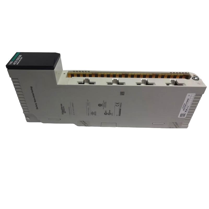
The Schneider 140ACO02000 Analog Output Module may be investigated when an industrial control system experiences missing output signals, incorrect actuator commands, unstable analog values, or module-related alarms. Effective troubleshooting requires separating module faults from controller configuration, wiring problems, power issues, and connected field-device failures. This guide outlines a structured process for diagnosing output faults, testing the installation, evaluating repair options, and verifying system operation after corrective work.
Technical note: Confirm the exact output types, channel configuration, terminal assignments, electrical ratings, and diagnostic functions for the specific 140ACO02000 installation. The procedures below are general industrial troubleshooting guidance and do not replace the applicable equipment documentation.
1. Schneider 140ACO02000 Common Fault Symptoms
The first step is to describe the actual symptom and identify which part of the control loop is affected. A field device that does not respond to a command does not necessarily indicate that the analog output module has failed.
- No output response: The connected device does not respond when the controller command changes.
- Output value is incorrect: The field device receives a command that differs from the intended value.
- Unstable output: The output or associated process response fluctuates unexpectedly.
- Module recognition fault: The host controller reports a missing, unavailable, or uninitialized module.
- Unexpected actuator behavior: A valve, drive, or other controlled device moves or responds differently from the intended command.
- Recurring alarms: A diagnostic condition returns after a reset or system restart.
These symptoms can be caused by external wiring, configuration errors, interlocks, field-device faults, or power problems. Establish evidence before replacing the module.
2. Schneider 140ACO02000 Troubleshooting Safety
Analog outputs may control equipment capable of movement, pressure changes, heating, or other hazardous process actions. Troubleshooting must be carried out by qualified personnel under approved site procedures.
- Place the process and connected machinery in an approved safe state.
- Apply lockout/tagout and verify isolation where required.
- Follow the equipment’s instructions for stored energy and discharge intervals.
- Use appropriate electrostatic discharge protection when handling the module.
- Use correctly rated instruments and documented test points.
- Do not bypass interlocks or force outputs without an approved test plan.
Never disconnect or reconnect module wiring under power unless the applicable equipment documentation explicitly permits the procedure and qualified personnel follow its requirements.
3. Schneider 140ACO02000 Initial Diagnostic Checks
3.1 Record Controller Commands and Alarms
Before resetting the system, record the exact alarm text, controller command, affected output channel, process condition, and any available diagnostic information. Determine whether the issue began after a module replacement, wiring change, software update, power interruption, or field-device maintenance.
3.2 Inspect Wiring and Connectors
After establishing a safe maintenance condition, inspect the module and field wiring for:
- Loose terminals or incompletely seated connectors.
- Incorrectly identified wires or channel connections.
- Damaged insulation, corrosion, or contamination.
- Improper shielding or grounding relative to the system design.
- Pinched cables or connections under mechanical strain.
- Signs of overheating or physical damage.
Check both ends of the output circuit. A correct connection at the module does not guarantee that the cable is correctly connected at the receiving device.
3.3 Verify Power and System Status
Review the host controller’s status and verify relevant power conditions using the specified test points. Check whether the module is recognized, whether the intended output channel is configured, and whether the controller has placed the output in a fault or inhibited state.
Do not infer the module’s supply voltage or terminal pinout from the model number. Use the exact documentation for all electrical measurements.
4. Schneider 140ACO02000 No-Output Troubleshooting
If the connected device does not respond, follow the output path from the controller command to the field device. The following is a general diagnostic sequence, not a verified internal circuit diagram for the module.
Controller Output Command
          |
          v
Check Logic, Mode and Interlocks
          |
          v
Verify Module Recognition and Configuration
          |
          v
Inspect Output Wiring and Connections
          |
          v
Measure at Approved Test Point
          |
          v
Check Receiving Device and Power
          |
          v
Confirm Correct System Response
4.1 Verify the Controller Command
Confirm that the controller is issuing the expected command and that the output is not being overridden by an interlock, manual mode, sequence condition, or fault response. Check whether the relevant control logic is enabled and whether the correct channel is assigned to the intended device.
4.2 Check the Output Circuit
Use the approved wiring diagram to verify terminal assignments, polarity where applicable, cable continuity, and the receiving device’s input requirements. Perform electrical measurements only at documented test points and under the conditions permitted by the equipment procedure.
4.3 Check the Receiving Device
A valve positioner, drive, actuator, or other field device may fail to respond because it lacks power, is in the wrong operating mode, has an active fault, or is configured for a different command interface. Confirm the receiving device’s own diagnostics and input configuration before attributing the fault to the output module.
5. Schneider 140ACO02000 Incorrect Output Troubleshooting
5.1 Verify Signal Type and Scaling
Confirm that the module’s configured output type matches the receiving device. Review the relationship between the controller’s engineering value and the expected physical output. An incorrect range, scaling factor, or channel mapping can produce a consistent but incorrect command.
Do not assume the module uses a particular current or voltage range without verifying the applicable specification.
5.2 Compare Command and Measurement
Where the procedure allows, compare the controller command with a measurement taken at the designated test point. Then compare the result with the receiving device’s documented input requirements. If the command is correct but the measured output is not, investigate configuration, wiring, loading, and module diagnostics. If the measured output is correct but the device behaves incorrectly, examine the field device and the downstream process.
5.3 Check Calibration Requirements
Determine whether the installed system requires calibration or a documented adjustment procedure. Do not compensate for a suspected hardware fault by arbitrarily changing scaling or calibration values. Preserve the original settings and record any authorized changes.
6. Schneider 140ACO02000 Unstable Output Troubleshooting
Fluctuating outputs can result from electrical interference, loose wiring, unstable power, a changing controller command, control-loop tuning, or problems with the receiving device. Begin by checking whether the command itself is stable.
- If the controller command fluctuates, investigate the control logic, feedback signal, and loop behavior.
- If the command is stable but the measured output fluctuates, inspect wiring, grounding, power conditions, and the module using approved tests.
- If the electrical output is stable but the field device moves irregularly, investigate the receiving device, its power supply, and mechanical or process conditions.
- If the problem occurs only under certain operating conditions, record those conditions and compare them with diagnostic data.
Do not adjust control-loop settings until the electrical signal path and field-device condition have been checked. Changing controller tuning can conceal the symptom without correcting the underlying hardware problem.
7. Schneider 140ACO02000 Common Faults and Corrective Actions
7.1 Module Not Recognized by the Controller
Check module seating, rack compatibility, hardware revision, power conditions, and controller configuration. Review the exact diagnostic message and confirm that the replacement module is compatible with the installed system.
7.2 Output Remains at an Unexpected Value
Review the controller command, channel assignment, output mode, interlocks, scaling, and fault-state behavior. Verify the electrical signal using approved test points and compare it with the receiving device’s specification.
7.3 Fault Returns After Reset
A reset may clear an alarm temporarily without correcting its cause. Preserve the original diagnostic information, determine the conditions that trigger the fault, and investigate the relevant part of the output loop before resetting again.
7.4 Output Fault Persists After Module Replacement
Recheck the field wiring, controller configuration, receiving device, rack interface, and power conditions. Confirm that the replacement is the correct part and that any required configuration has been restored. If the symptom remains unchanged, the original diagnosis may have overlooked an external cause.
7.5 Visible Damage or Overheating
If the module shows signs of burning, corrosion, or physical damage, isolate the equipment and investigate the underlying cause. Check the documented supply and wiring arrangements for possible shorts or abnormal conditions. Do not return a visibly damaged module to service without an appropriate technical assessment.
8. Schneider 140ACO02000 Repair and Replacement Assessment
Repair decisions should be based on diagnostic evidence, the module’s actual design, and the requirements of the application. A qualified repair facility may assess connector damage, circuit-board defects, and specified electronic test points when suitable documentation and test equipment are available.
Replacement may be appropriate when the fault is confirmed, the module has extensive damage, or reliable repair and verification cannot be completed. Confirm the exact model, revision, connector arrangement, and host-system compatibility before installation.
Do not substitute a similar-looking module solely because its dimensions or connector arrangement appear compatible. Differences in output characteristics or configuration requirements can affect connected equipment and process safety.
9. Schneider 140ACO02000 Post-Repair Verification
After repair or replacement, perform the approved commissioning procedure before returning the control loop to normal operation.
- Check module installation, connectors, and wiring against the approved diagrams.
- Verify the required configuration, channel assignments, and scaling.
- Restore power using the documented startup sequence.
- Confirm that the controller recognizes the module and review active alarms.
- Test output response under controlled and approved conditions.
- Verify that the receiving device responds as intended and that the original symptom has cleared.
- Record the root cause, corrective action, and test results.
10. Schneider 140ACO02000 Troubleshooting FAQs
Does a missing analog output always mean the module has failed?
No. The cause may be an inactive controller command, an interlock, incorrect configuration, damaged wiring, a power problem, or a fault in the receiving device. Diagnose the complete output path before replacing the module.
Why does the output value differ from the controller command?
Possible causes include incorrect scaling, channel mapping, signal compatibility, wiring, configuration, loading, or a module-related fault. Compare the command with measurements taken at approved test points.
Can the Schneider 140ACO02000 be tested with a multimeter?
A suitable instrument may be used for specified measurements when the procedure permits it. Confirm the correct test points, expected signal type, measurement method, and electrical safety requirements before testing.
Should I replace the module if the output is unstable?
Not immediately. First determine whether the controller command itself is fluctuating, then check wiring, grounding, power conditions, configuration, and the receiving device. Replace the module only when evidence supports that decision.
What information should be recorded during troubleshooting?
Record the complete model and revision, controller diagnostics, affected channel, controller command, approved measurement results, wiring checks, recent maintenance, corrective actions, and post-repair test results.
11. Schneider 140ACO02000 Troubleshooting Technical Summary
Reliable troubleshooting of the Schneider 140ACO02000 Analog Output Module requires a systematic examination of controller commands, configuration, electrical output, field wiring, and receiving-device behavior. A missing or incorrect output should not automatically be attributed to a failed module. Verify the actual module specifications and use approved test points for all measurements. After repair or replacement, complete a controlled functional test and document the results to help prevent repeat failures and reduce industrial automation downtime.