
NewsNEWCENTER
Featured products


Contact Us
Schneider 140ACO02000 Analog Output Module Installation Guide
2026-10-14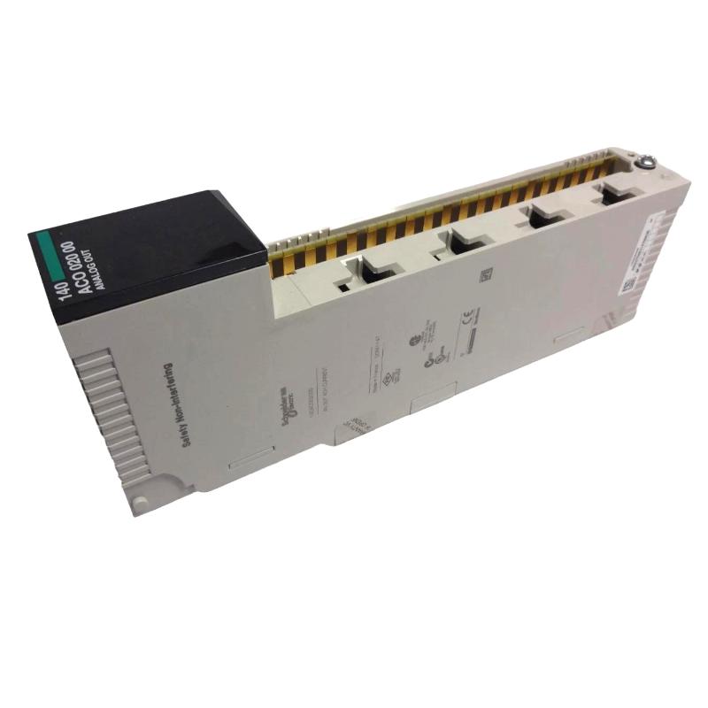
The Schneider 140ACO02000 Analog Output Module is an industrial automation component intended for use in compatible control-system applications. Correct installation involves confirming the module’s exact specifications, checking rack and controller compatibility, verifying output wiring, and completing functional commissioning before the equipment returns to normal operation. This Schneider 140ACO02000 installation guide explains preparation, mounting, electrical integration, configuration, testing, and maintenance considerations for industrial engineers and automation technicians.
Technical note: Verify the exact function, output signal types, channel configuration, electrical ratings, terminal assignments, and compatibility requirements from the documentation for the specific module and host system. Do not assume these details from the model number alone.
1. Schneider 140ACO02000 Analog Output Module Overview
An analog output module typically converts controller commands into electrical signals used by compatible field devices. Depending on the control-system design, these signals may be used to adjust a process variable, provide a reference command, or regulate an external device. The exact capabilities of the Schneider 140ACO02000 must be confirmed before it is connected to field equipment.
In a typical industrial automation architecture, the controller calculates an output value, the output module generates the corresponding electrical signal, and a compatible field device responds to that command. Incorrect wiring, scaling, or configuration can cause an output to behave differently from the controller’s intended command.
2. Schneider 140ACO02000 Installation Preparation
2.1 Verify Model and Compatibility
- Confirm that the product label identifies the module as Schneider 140ACO02000.
- Record the hardware revision and any additional identification markings.
- Verify compatibility with the target rack, controller, backplane, and engineering software.
- Confirm the supported output types and electrical ranges in the applicable documentation.
- Check whether the application requires channel mapping, output scaling, calibration, or specific configuration settings.
2.2 Prepare the Installation Environment
Before opening the control cabinet, place the process in an approved maintenance state. Isolate the relevant power sources, apply lockout/tagout procedures where required, and verify the absence of hazardous voltage. Follow the host equipment’s instructions for handling stored electrical energy.
Use electrostatic discharge protection when handling the module. Keep the board away from conductive debris, moisture, and unnecessary contact with exposed connectors. Ensure that the cabinet environment meets the requirements specified for the installed equipment.
2.3 Inspect the Module and Receiving Slot
Inspect the module for damaged connectors, bent contacts, cracked housing, corrosion, contamination, or visible overheating. Check the receiving slot and mating connector for similar problems. A defective rack interface can cause startup failures even when the module itself is functional.
3. Schneider 140ACO02000 Module Installation Procedure
3.1 Record the Existing Installation
If the module is being replaced, document its slot position, cable labels, terminal arrangement, configuration settings, and any active diagnostic messages. Photographing the existing installation can help prevent wiring errors. Preserve the required configuration and calibration information before removing the original assembly.
3.2 Remove the Existing Module
- Confirm that the connected process is in a safe state.
- Isolate the relevant power supplies and verify the equipment is safe to handle.
- Identify the module and release its designated retaining hardware.
- Disconnect wiring only after verifying that the connections are de-energized and safe to handle.
- Withdraw the module according to the host equipment’s removal procedure.
- Inspect the removed module and rack connector for visible damage.
Do not force the module out of its slot. If it does not release normally, check for locking clips, retaining screws, or other mechanical restraints.
3.3 Install the Schneider 140ACO02000
- Verify the replacement part number, revision, and compatibility.
- Align the module with the designated rack guides and connector.
- Insert the module evenly without twisting or applying excessive force.
- Secure the module using the specified retention mechanism.
- Reconnect labeled terminal assemblies or cables according to the approved wiring documentation.
- Check that all connectors are seated correctly and cables are free from mechanical strain.
If the module does not align correctly, stop and verify its orientation, slot assignment, and connector compatibility. Never modify a connector or force an incompatible module into the rack.
4. Schneider 140ACO02000 Analog Output Wiring
Correct wiring is essential because an analog output signal may directly influence a valve positioner, drive reference, actuator, or other control device. The actual output interface and terminal assignments for the Schneider 140ACO02000 must be confirmed from the relevant technical documentation.
The following diagram illustrates a general analog control path. It is not a verified terminal-level wiring diagram for this model.
Controller Logic or Setpoint
             |
             v
Schneider 140ACO02000
Analog Output Module
             |
             v
Verified Output Interface
             |
             v
Compatible Field Device
             |
             v
Process Response / Feedback
             |
             v
Controller Monitoring
4.1 Verify Output Wiring
- Confirm the output channel and terminal assignments from the correct documentation.
- Verify that the connected device accepts the module’s supported signal type and range.
- Check polarity and common connections where applicable.
- Inspect cable shielding and grounding according to the system design.
- Separate low-level analog wiring from sources of electrical interference where required.
- Confirm that field devices are powered and configured according to their own specifications.
Do not connect an unidentified field device or apply an arbitrary external signal to a module terminal. An incorrect connection can damage the module or produce unintended movement in connected equipment.
4.2 Check Output Scaling and Engineering Units
Controller output values often use engineering units or normalized numerical ranges. The configured scaling must correspond to the connected device’s input requirements. For example, a valve command and a speed reference may use different engineering ranges and scaling conventions.
Verify the complete conversion from the controller command to the physical output signal. Confirm that minimum, maximum, and intermediate commands produce the intended response using approved test procedures.
5. Schneider 140ACO02000 Configuration and System Integration
After physical installation, verify that the host controller recognizes the module and that the correct output channels are assigned to the intended control functions. Depending on the system design, configuration may involve rack identification, software settings, channel mapping, scaling, output behavior during faults, or diagnostic parameters.
5.1 Configuration Checklist
- Confirm the module is assigned to the correct rack or slot.
- Verify controller and module compatibility.
- Check output channel assignments and engineering-unit scaling.
- Review fault-state behavior and interlock requirements.
- Confirm that the connected field devices are mapped to the correct outputs.
- Save the approved configuration and record any changes.
Do not assume that a module replacement automatically restores every parameter. Follow the system’s approved configuration backup and recovery process.
6. Schneider 140ACO02000 Commissioning and Functional Testing
6.1 Pre-Startup Inspection
Before energizing the equipment, check that the module is secure, all connectors are seated, wiring matches the approved diagram, and protective covers are installed. Remove tools and loose hardware from the cabinet. Confirm that connected machinery and actuators can be tested safely.
6.2 Controlled Startup
- Restore power according to the host system’s approved startup procedure.
- Check available module status indications and controller diagnostics.
- Confirm that the controller recognizes the module where supported.
- Review active alarms before enabling output-dependent equipment.
- Test the outputs under controlled conditions using the documented procedure.
Where an output controls a moving machine, valve, or other potentially hazardous device, establish the required safe state before testing. Do not bypass interlocks or force an output in a way that could create an unsafe process condition.
6.3 Verify Output Response
Use approved test points and suitable instruments to verify the output signal. Compare the measured result with the configured command and the field device’s requirements. Test multiple operating points where the approved commissioning procedure permits, rather than relying on a single reading.
Confirm that the field device responds correctly and that any available feedback agrees with the expected process behavior. If the output does not match the command, investigate scaling, wiring, loading, configuration, and the connected device before concluding that the module is defective.
7. Common Schneider 140ACO02000 Installation Problems
- Module not recognized: Check seating, slot assignment, compatibility, power conditions, and controller configuration.
- No output response: Verify the output channel assignment, operating mode, interlocks, wiring, and connected device.
- Incorrect output level: Review signal compatibility, scaling, calibration requirements, and approved measurement results.
- Unstable output: Inspect connections, grounding, shielding, electrical interference, and field-device behavior.
- Unexpected actuator movement: Stop testing safely and verify command mapping, output scaling, control logic, and interlocks before further operation.
8. Schneider 140ACO02000 Maintenance Recommendations
Maintain a record of the installed model, hardware revision, rack position, wiring changes, configuration settings, and commissioning results. During scheduled maintenance, inspect the cabinet for dust, moisture, corrosion, excessive temperature, loose connections, and vibration.
Periodically review the relationship between controller commands and field-device responses as part of the site’s approved maintenance program. Any calibration or output test must follow the procedures and limits specified for the actual module and connected equipment.
9. Schneider 140ACO02000 Analog Output Module Installation FAQs
What should be verified before installing the Schneider 140ACO02000?
Confirm the full model number, revision, rack compatibility, supported output interface, electrical requirements, terminal assignments, and configuration needs.
Can the 140ACO02000 be removed while the system is powered?
Do not assume that live replacement is supported. Follow the host system’s maintenance instructions and isolate power unless the documentation explicitly permits hot swapping under defined conditions.
Why is output scaling important?
Scaling determines how controller values correspond to physical output signals and field-device commands. Incorrect scaling can cause a connected device to operate outside its intended range.
How can the output module be tested after installation?
Use the approved commissioning procedure, suitable test equipment, documented test points, and controlled output commands. Verify both the electrical output and the connected device’s response.
10. Schneider 140ACO02000 Installation Technical Summary
Successful installation of the Schneider 140ACO02000 Analog Output Module depends on verified hardware compatibility, safe handling, correct wiring, appropriate output scaling, and controlled commissioning. Engineers should confirm the module’s actual specifications and terminal assignments before connecting field devices. A documented functional test helps establish that controller commands are translated into the expected electrical outputs and that the connected equipment responds safely.