

ProductPRODUCT
Featured products
Contact Us
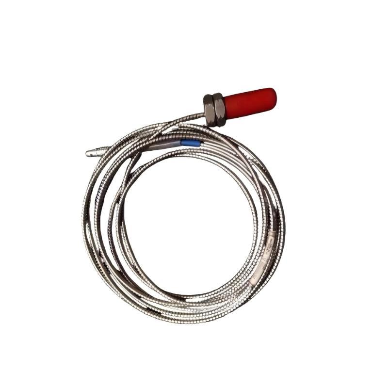
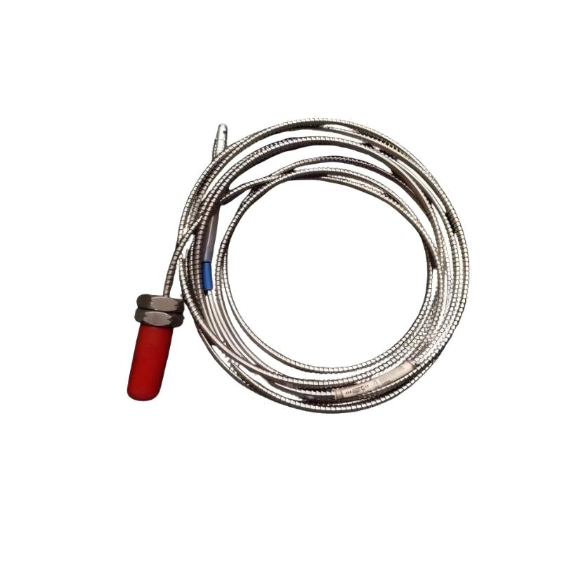
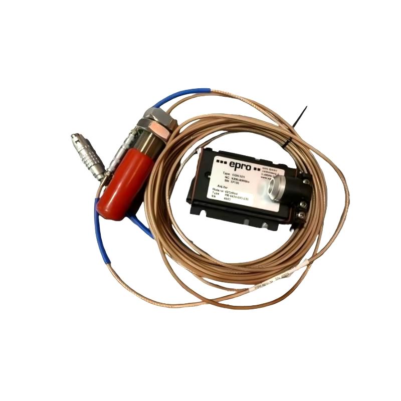
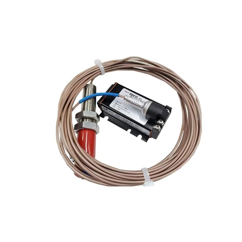
- Epro
- PR6424/004-030
- 16 mm Eddy Current Sensor
- Germany
- 16 mm
- 0.2 kg
- Xiamen, China
- New & In Stock
- T/T, PayPal, Western Union
- 1 Year
- 1-3 Working Days
- DHL, UPS, TNT, FedEx and EMS.
- 24-Hour Service
- COO
- 6
Our advantage

Global Logistics
We have a 10-year logistics and express cooperation agreement, so our products can be shipped to any place in the world.

Brand new and original
Our products are imported in bulk from the place of origin. Because of the cooperative relationship, our products are all original and 100% new.

24-hour service
We provide 7*24 hours service to our customers. We will be there whenever you need us.

Price advantage
All our products are priced very favorably because we have our own warehouse and supply.
| Company Information | |||
| [email protected] | |||
| Mobile | +8615980777398 | ||
| +8615980777398 | |||
| 15980777398 |
1. Product Overview
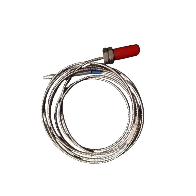
The Epro PR6424/004-030 16 mm Eddy Current Sensor is an industrial sensing component designed for non-contact measurement of conductive metal targets. Eddy current technology is widely used in machinery monitoring because it can detect changes in the distance between a probe and a metal surface without requiring direct physical contact.
In industrial automation and equipment protection applications, reliable displacement and vibration measurements help maintenance teams evaluate rotating machinery conditions. Eddy current sensors are commonly used in suitable monitoring arrangements for turbines, compressors, pumps, motors, and other rotating equipment.
The Epro PR6424/004-030 has a specified sensor head diameter of 16 mm and a listed weight of 0.2 kg. These characteristics are useful for product identification, installation planning, spare-parts management, and replacement evaluation.
For industrial maintenance engineers and system integrators, selecting the correct sensor configuration is essential. The complete model number, measurement range, cable arrangement, electrical characteristics, and compatibility with associated signal conditioning equipment should be verified before installation.
2. Technical Specifications
| Parameter | Specification |
|---|---|
| Brand | Epro |
| Model | PR6424/004-030 |
| Product Type | Eddy Current Sensor |
| Sensor Head Diameter | 16 mm |
| Weight | 0.2 kg |
| Sensing Principle | Eddy current, non-contact measurement |
| Target Material | Conductive metal |
| Typical Application | Displacement and machinery vibration monitoring |
| Mounting Arrangement | According to the specific sensor configuration |
| Signal Processing | Requires a compatible measurement interface |
| Measuring Range | Verify against the exact model documentation |
| Sensitivity | Verify against the exact model documentation |
| Frequency Response | Verify against the exact model documentation |
| Cable Configuration | Confirm before installation |
| Operating Temperature | Confirm the specified operating limits |
| System Compatibility | Verify against the complete monitoring system |
The dimensions and weight above reflect the supplied product information. Other technical parameters should be confirmed using the documentation for the exact PR6424/004-030 configuration rather than inferred from the model series.
3. Function and Working Principle
3.1 Eddy Current Sensing Technology
An eddy current sensor generates an alternating electromagnetic field around its sensing element. When a conductive target enters this field, electrical currents are induced in the target surface. These currents influence the electromagnetic field and change the electrical response of the sensing system.
Associated electronics evaluate the changes and convert them into a measurement signal related to the distance between the probe and the target.
Because measurement takes place without direct contact, this technology is suitable for many applications involving moving metal components. Correct operation depends on the sensor being installed within its specified measurement range and connected to compatible signal conditioning equipment.
3.2 Displacement Measurement
In machinery monitoring, an eddy current sensor can be positioned near a conductive shaft or other target to detect changes in the gap between the probe and the surface.
Depending on the installation design, these measurements can be used to monitor relative shaft position, displacement, or other movement-related parameters. The direction of measurement and the interpretation of the signal depend on the sensor mounting arrangement and the connected monitoring system.
Accurate results require secure mounting, correct alignment, and an appropriate initial gap. Incorrect positioning can cause measurement errors or an output that falls outside the intended operating range.
3.3 Vibration Monitoring
Eddy current technology is commonly used for non-contact shaft vibration measurements in compatible machinery monitoring systems. As a rotating shaft moves relative to the probe, the distance between the shaft surface and sensor changes.
The monitoring system processes these changes to evaluate vibration behavior. Maintenance personnel can compare the resulting data with historical measurements and established operating baselines to identify changes that may require investigation.
The final measurement performance depends on the complete measurement chain, including the probe, any required extension cable, signal conditioner, monitoring module, and configuration settings.
3.4 Continuous Condition Monitoring
When incorporated into an appropriate system, the sensor can provide continuous measurement data during machine operation. Monitoring equipment can use these measurements for trend analysis, alarm evaluation, and maintenance planning.
Continuous monitoring is particularly valuable in facilities where unexpected equipment downtime can affect production schedules, maintenance costs, and plant availability.
4. Role in Industrial Machinery Monitoring Systems
Rotating Machinery Assessment
Rotating equipment can experience changes in shaft position and vibration because of operating conditions, mechanical wear, alignment problems, or other factors. A suitable eddy current sensor can provide non-contact measurements that help engineers evaluate these changes.
The PR6424/004-030 should be selected for a specific machine only after its verified performance and compatibility have been compared with the application requirements.
Condition-Based Maintenance
Measurement trends can help maintenance teams identify deviations from normal operating conditions. A change in displacement or vibration may indicate the need for further inspection, but the measurement alone does not establish the root cause of a fault.
For a more complete assessment, engineers should consider machine speed, load, temperature, operating history, and other relevant sensor readings.
Integration with Monitoring Equipment
The sensor may be used within a broader monitoring arrangement containing signal conditioning equipment, monitoring modules, protection systems, data acquisition devices, and control interfaces.
The exact connection method depends on the sensor’s electrical characteristics and the architecture of the monitoring system. Compatibility should be confirmed before the probe is connected to any input module.
Operational Reliability
Consistent measurement data can help plant personnel identify developing problems, evaluate maintenance needs, and establish reference conditions for future troubleshooting. Reliable results depend on correct installation and a properly configured measurement chain.
5. Industrial Applications
5.1 Steam and Gas Turbines
Turbines require suitable monitoring of rotating components to help assess mechanical operating conditions. Eddy current sensors are commonly used in appropriate turbine monitoring systems to measure shaft movement without physical contact.
The PR6424/004-030 may be evaluated for these applications when its documented measurement characteristics and system compatibility meet the requirements of the installation.
5.2 Industrial Compressors
Compressors in petrochemical, chemical processing, and other continuous-process facilities often operate under demanding conditions. Shaft displacement and vibration measurements can contribute to equipment condition assessment and maintenance planning.
Selection should consider the compressor design, shaft material, probe mounting position, measurement range, and associated electronics.
5.3 Pumps and Rotating Equipment
Industrial pumps and other rotating machines can benefit from condition monitoring where shaft movement needs to be measured without contact. Suitable eddy current sensing arrangements can provide data for evaluating changes in operating behavior.
5.4 Electric Motors
Large motors and associated rotating equipment may use non-contact sensors as part of a broader vibration monitoring strategy. Sensor data can be reviewed alongside thermal, electrical, and mechanical measurements.
5.5 Power Generation and Process Industries
Power stations and process plants frequently use integrated monitoring systems to assess critical equipment. Properly selected eddy current sensors can provide measurement inputs for trend analysis and fault investigation.
6. Installation and System Integration
Correct installation is essential for measurement accuracy and long-term reliability. The following steps provide a general checklist; the approved instructions for the exact sensor configuration must take precedence.
Step 1: Verify the Model Number
Confirm that the product label identifies the sensor as Epro PR6424/004-030. Compare the model number and connection arrangement with the existing equipment documentation.
Do not assume that sensors in the same product series share identical electrical characteristics, measurement ranges, or cable requirements.
Step 2: Inspect the Sensor
Check the probe head, cable, connector, and mounting components for visible damage. Look for contamination, corrosion, deformation, crushed cable sections, or damaged contacts.
If the sensor has been exposed to impact or excessive environmental stress, verify its condition before installation.
Step 3: Prepare the Mounting Location
Choose a mounting position that provides adequate mechanical stability and sufficient clearance from the moving target.
The 16 mm sensor head diameter is a useful dimensional reference, but the mounting bore, thread, bracket dimensions, and total installation clearance must be checked against the actual hardware.
Step 4: Set the Probe Gap
Position the sensor according to the specified mounting procedure. Establish the required gap between the probe and target using an approved method.
Ensure that expected machine movement will not cause contact between the sensor and the rotating component. Do not estimate the installation gap by sight alone.
Step 5: Route the Cable
Protect the cable from abrasion, crushing, excessive bending, high temperatures, and moving machinery. Follow the installation requirements for separation from potential electrical interference sources.
If the system uses an extension cable, verify that its type and length are compatible with the probe and associated electronics.
Step 6: Verify Signal Conditioning
Confirm that the connected signal conditioner or monitoring module supports the exact sensor configuration. Check the electrical interface, connector arrangement, and applicable system requirements.
Do not assume that the probe can connect directly to a standard PLC analog input without suitable interface equipment.
Step 7: Commission the Measurement System
After installation, verify the mounting position, cable connections, and configuration of the associated electronics. Check that the monitoring system displays a plausible measurement and that the signal responds as expected under the approved test procedure.
Investigate any unstable or out-of-range signal before returning the monitored equipment to service.
Step 8: Record Baseline Conditions
Document the sensor model, installation location, probe gap, cable arrangement, associated monitoring equipment, and commissioning results. Record baseline measurements under known operating conditions where applicable.
These records provide a useful reference for future troubleshooting and condition monitoring.
7. Troubleshooting Common Problems
Problem 1: No Signal Output
Possible causes:
- Disconnected or damaged cable.
- Incorrect connector or wiring arrangement.
- Incompatible signal conditioning equipment.
- Missing power to associated electronics.
- Faulty probe or monitoring input.
Recommended checks:
Inspect the complete measurement path from the sensor to the monitoring equipment. Verify the connections and confirm that the associated electronics support the exact probe configuration. Test the cable and sensor according to the approved procedure before replacing components.
Problem 2: Unstable or Fluctuating Readings
Possible causes:
- Loose mounting hardware.
- Incorrect probe gap.
- Excessive vibration at the mounting bracket.
- Electrical interference.
- Cable damage or poor connections.
- Unsuitable target surface conditions.
Recommended checks:
Inspect the mounting arrangement and cable routing. Verify the initial gap and review the signal conditioning configuration. Compare the readings with the machine’s operating state to determine whether the fluctuations represent actual shaft movement or a problem in the measurement chain.
Problem 3: Readings Outside the Expected Range
Possible causes:
- Incorrect installation gap.
- Incompatible probe and signal conditioner.
- Incorrect scaling or configuration settings.
- Unsuitable target material or geometry.
- Damaged cable or sensor.
Recommended checks:
Verify the probe position and compare the monitoring equipment settings with the applicable documentation. Confirm the measuring range and scaling parameters. Avoid changing alarm thresholds simply to suppress an abnormal reading before the underlying cause is understood.
Problem 4: Inconsistent Results After Replacement
Possible causes:
- Incorrect replacement model.
- Different cable configuration.
- Incorrect mounting gap.
- Incompatible signal conditioning.
- Incomplete commissioning.
Recommended checks:
Verify the full part number and system configuration. Inspect the cable arrangement, confirm the probe gap, and repeat the approved commissioning procedure. Record the verified results for future maintenance.
Problem 5: Physical Damage
A non-contact sensor can still be damaged by accidental impact, incorrect mounting, contamination, excessive heat, or contact with a moving component.
Inspect the probe and mounting arrangement. If the sensor’s condition or measurement performance cannot be verified, test or replace it according to the site’s approved maintenance procedure.
Safety note: Follow the plant’s isolation and lockout procedures before inspecting or replacing sensors near operating machinery. If the sensor participates in a machine protection function, follow the approved procedures for maintaining that protection function.
8. Compatible System Components
The PR6424/004-030 should be assessed as part of the complete measurement chain. The following table describes typical component categories and does not confirm compatibility with any specific part number.
| Component Category | Function | Verification Requirement |
|---|---|---|
| Signal Conditioner | Processes the probe response into a usable measurement signal | Must support the exact sensor configuration |
| Extension Cable | Connects the probe to associated electronics when required | Type and length must meet system requirements |
| Machinery Monitoring Module | Processes displacement or vibration measurements | Must support the specified input characteristics |
| Protection Monitoring System | Evaluates measurements against configured alarm and trip limits | Must be designed for the complete measurement chain |
| Data Acquisition Equipment | Records measurements for analysis and trending | Input range and interface must be appropriate |
| Probe Mounting Hardware | Secures the sensor near the target | Must match the actual sensor and machine design |
| Industrial Control Interface | Transfers monitoring data to other systems where supported | Requires a compatible interface or monitoring-system connection |
Before purchasing related components, confirm the probe configuration, cable requirements, signal conditioning characteristics, and monitoring system architecture. Shared branding alone does not establish compatibility.
9. Recommended Alternative Models and Replacement Selection
When the original sensor is unavailable, evaluate alternatives using documented technical compatibility rather than appearance or head diameter alone.
| Replacement Option | When to Consider It | Important Checks |
|---|---|---|
| Epro PR6424/004-030 | Preferred when the existing system requires this exact model | Full part number, condition, and system compatibility |
| Another Epro 16 mm Eddy Current Sensor | When an alternative within the product family is being evaluated | Measurement range, sensitivity, electrical interface, and cable arrangement |
| Compatible Eddy Current Probe Assembly | When an approved alternative assembly is available | Probe, cable, signal conditioner, and mounting compatibility |
| Alternative Monitoring Sensor System | When upgrading or redesigning the monitoring arrangement | Measurement requirements, interfaces, calibration, and commissioning |
A different 16 mm sensor is not automatically a direct replacement. Confirm the required performance characteristics, electrical interface, mounting details, and compatibility with the existing monitoring equipment before ordering.
10. Key Advantages of Eddy Current Sensing
Non-Contact Measurement
Eddy current technology measures conductive targets without direct physical contact. This is useful for suitable applications involving moving or rotating metal components.
Continuous Measurement Capability
When connected to a compatible monitoring system, the sensor can provide ongoing measurement data for condition assessment and trend analysis.
Support for Rotating Machinery Monitoring
Eddy current sensors are commonly used in appropriate shaft displacement and vibration measurement arrangements, helping maintenance personnel assess changes in machine behavior.
Integration into Industrial Monitoring Systems
The sensor can act as a sensing component within a broader measurement chain involving signal conditioning, monitoring modules, data acquisition, and alarm management.
Defined Physical Characteristics
The specified 16 mm sensor head diameter and 0.2 kg weight provide useful reference information for identification, storage, and installation planning.
11. Technical FAQs
Q1: What is the Epro PR6424/004-030?
It is a 16 mm Epro eddy current sensor designed for non-contact measurement applications involving conductive targets. Its suitability for a specific machine depends on the verified technical characteristics and system requirements.
Q2: What is the sensor head diameter?
The specified sensor head diameter is 16 mm.
Q3: What is the weight of the PR6424/004-030?
The listed weight is 0.2 kg.
Q4: Can this sensor be used for shaft vibration monitoring?
Eddy current sensors are commonly used in non-contact shaft vibration monitoring. Confirm the measurement range, sensitivity, frequency response, and compatibility of this exact model with the complete monitoring system.
Q5: Can the sensor connect directly to a PLC?
Direct connection should not be assumed. The required interface depends on the sensor’s electrical characteristics and the PLC input design. A compatible signal conditioning or monitoring device may be required.
Q6: What should be checked before installation?
Verify the full model number, mounting dimensions, installation gap, cable arrangement, electrical interface, and compatibility with the associated monitoring equipment.
Q7: Why might the sensor produce unstable readings?
Potential causes include loose mounting, incorrect probe gap, electrical interference, damaged cabling, unsuitable target conditions, or incompatible signal conditioning. Check the entire measurement chain before replacing the probe.
Q8: Is another 16 mm sensor automatically compatible?
No. The same sensor head diameter does not establish interchangeability. The measurement range, sensitivity, electrical characteristics, cable configuration, and signal conditioning requirements must also be suitable.
Q9: How can measurement reliability be maintained?
Use the approved mounting procedure, inspect the sensor and cable periodically, maintain secure mounting, and monitor changes in measurement behavior. Keep installation and commissioning records for future troubleshooting.
Q10: What should buyers verify before ordering?
Confirm the complete model number, required quantity, physical condition, cable and connector configuration, application requirements, and compatibility with the existing monitoring system.
12. Conclusion
The Epro PR6424/004-030 16 mm Eddy Current Sensor is a non-contact sensing component for suitable industrial displacement and machinery monitoring applications. Its specified sensor head diameter of 16 mm and listed weight of 0.2 kg provide useful physical reference information for product identification, installation planning, and spare-parts purchasing.
Reliable operation depends on correct mounting, an appropriate measurement gap, compatible signal conditioning, proper cable routing, and systematic commissioning. Before installing or replacing the sensor, verify its exact configuration and compatibility with the complete monitoring system.
For industrial maintenance teams, automation engineers, and spare-parts purchasers, careful product verification helps reduce replacement errors and supports dependable machinery condition monitoring.