

ProductPRODUCT
Featured products
Contact Us
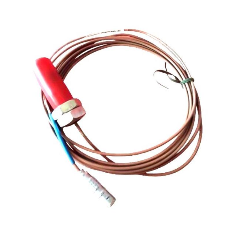
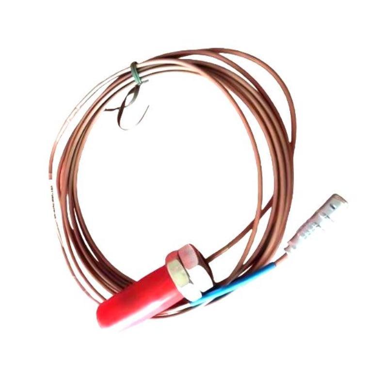
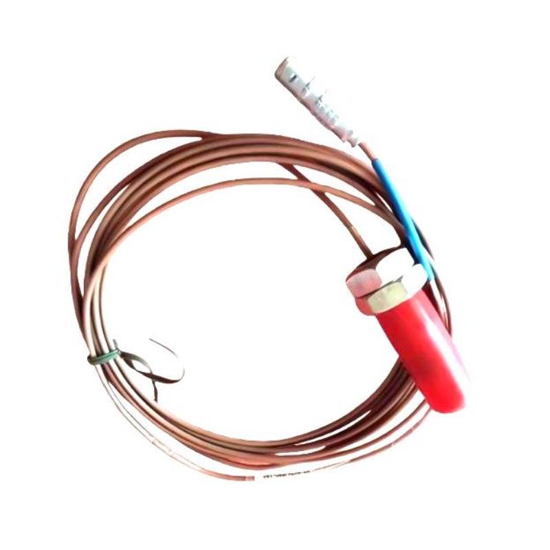
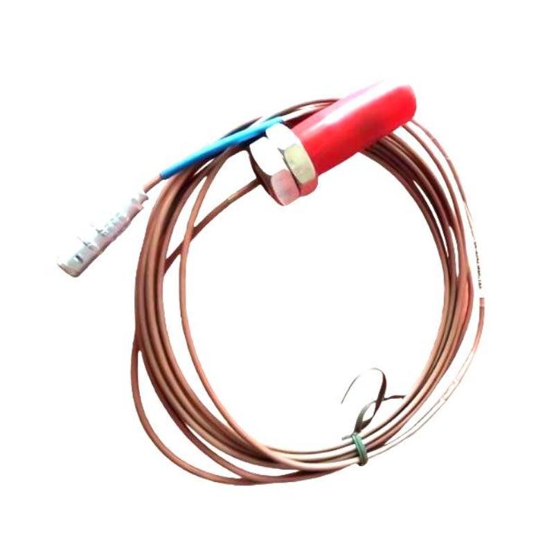
- Epro
- PR6424/002-021
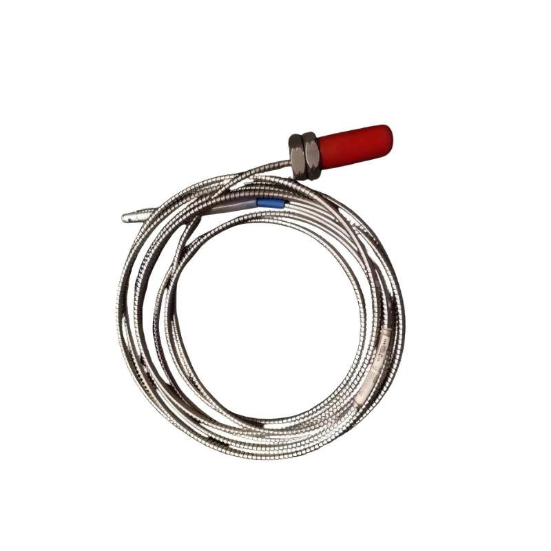
- 16 mm Eddy Current Sensor
- Germany
- 16 mm
- 0.2 kg
- Xiamen, China
- New & In Stock
- T/T, PayPal, Western Union
- 1 Year
- 1-3 Working Days
- DHL, UPS, TNT, FedEx and EMS.
- 24-Hour Service
- COO
- 4
Our advantage

Global Logistics
We have a 10-year logistics and express cooperation agreement, so our products can be shipped to any place in the world.

Brand new and original
Our products are imported in bulk from the place of origin. Because of the cooperative relationship, our products are all original and 100% new.

24-hour service
We provide 7*24 hours service to our customers. We will be there whenever you need us.

Price advantage
All our products are priced very favorably because we have our own warehouse and supply.
| Company Information | |||
| [email protected] | |||
| Mobile | +8615980777398 | ||
| +8615980777398 | |||
| 15980777398 |
1. Product Overview
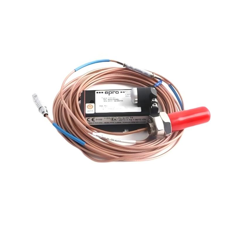
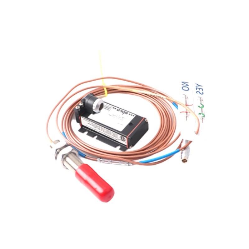
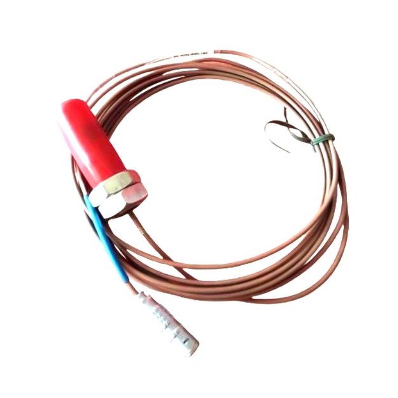
The Epro PR6424/002-021 16 mm Eddy Current Sensor is an industrial non-contact displacement sensor designed for applications involving the measurement of shaft position, relative displacement, and mechanical movement. Eddy current sensing technology is widely used in rotating machinery monitoring because it measures the distance to a suitable conductive target without requiring physical contact.
In industrial environments, accurate displacement measurements are important for evaluating machinery condition, monitoring shaft movement, and identifying changes in operating behavior. Turbines, compressors, pumps, and other rotating equipment may use non-contact sensors as part of a larger condition-monitoring or machinery protection system.
The PR6424/002-021 belongs to the Epro eddy current sensor product range. Its supplied sensor head diameter is 16 mm, and its listed weight is 0.2 kg. The larger sensor head diameter compared with an 8 mm probe does not, by itself, establish a particular measurement range, sensitivity, or performance level. These characteristics must be confirmed from the specifications for the exact model.
An eddy current sensor typically operates together with compatible signal-conditioning electronics, connecting cables, and a monitoring device. The complete measurement chain must be correctly matched and calibrated to provide dependable displacement information.
Before purchasing or installing the Epro PR6424/002-021, verify its electrical characteristics, probe and cable configuration, compatible driver, installation clearance, and calibration requirements. Sensors with similar dimensions may not be electrically interchangeable.
2. Technical Specifications
| Parameter | Specification |
|---|---|
| Brand | Epro |
| Model Number | PR6424/002-021 |
| Product Name | 16 mm Eddy Current Sensor |
| Product Category | Non-Contact Displacement Sensor |
| Sensor Head Diameter | 16 mm |
| Weight | 0.2 kg |
| Measurement Principle | Eddy current sensing |
| Target Type | Electrically conductive target |
| Typical Measurement Applications | Shaft displacement, relative position, and machinery movement |
| Measurement Range | Verify from exact model documentation |
| Sensitivity | Verify from exact model documentation |
| Frequency Response | Verify from exact model documentation |
| Output Characteristics | Depend on the compatible sensor electronics and monitoring system |
| Cable and Connector Configuration | Verify the exact supplied assembly |
| Signal Conditioner | Must be compatible with the specific probe |
| Installation Environment | Industrial machinery monitoring, subject to product ratings |
| Calibration | Follow the requirements for the complete probe-and-driver combination |
The table reflects the supplied product identification and physical specifications. Measurement range, sensitivity, frequency response, cable length, and electrical characteristics should be verified before commissioning.
3. Function and Working Principle
3.1 Eddy Current Sensing Technology
An eddy current sensor operates by generating an alternating electromagnetic field at the sensing face. When a conductive target enters this field, electrical currents known as eddy currents are induced in the target material.
These currents influence the electromagnetic characteristics of the sensor. The change depends on the distance between the sensor and the target, along with factors such as target material and the design of the measurement system.
Compatible signal-conditioning electronics interpret this response and convert it into a displacement-related signal. The monitoring equipment can then display, record, or analyze the measurement.
3.2 Non-Contact Displacement Measurement
Unlike contact-based measurement devices, an eddy current probe can measure movement without touching the target surface. This is particularly valuable when monitoring rotating shafts, where physical contact could cause wear or interfere with machine operation.
When a probe is positioned near a conductive shaft, changes in the gap between the sensing face and the shaft produce changes in the measurement signal. The resulting data can be used for appropriate displacement-monitoring applications.
3.3 Shaft Vibration Monitoring
During operation, a rotating shaft may move relative to its bearing housing because of vibration, imbalance, misalignment, or other mechanical conditions. A correctly installed eddy current sensor can measure changes in shaft-to-probe distance.
The monitoring system may use this data to evaluate shaft movement and identify deviations from established operating conditions. Actual measurement performance depends on probe calibration, target properties, installation geometry, and the characteristics of the complete measurement chain.
3.4 Probe and Driver Integration
An eddy current probe generally requires a compatible driver or signal conditioner. The electronics provide the necessary excitation and convert the probe response into a signal suitable for the monitoring system.
The probe, extension cable where applicable, and driver should be treated as a matched system. Using an incompatible cable or driver can affect calibration, measurement accuracy, and signal stability.
For the PR6424/002-021, the exact compatible electronics and cable arrangement must be confirmed before connection.
4. Role in Industrial Machinery Monitoring
4.1 Monitoring Shaft Position
Rotating machinery often requires measurement of the position of a shaft relative to a fixed reference. An eddy current sensor can provide this information when installed with the correct geometry and calibrated for the application.
Position measurements may help engineers evaluate operating clearances, monitor changes in shaft location, and investigate abnormal machine behavior.
4.2 Monitoring Axial Displacement
Some turbines, compressors, and other rotating machines require monitoring of movement along the shaft axis. Changes in axial position may indicate variations in thrust-bearing behavior, internal clearances, or mechanical operating conditions.
A suitable eddy current measurement arrangement can monitor axial movement when the probe orientation, target surface, measurement range, and monitoring system are appropriate.
4.3 Supporting Vibration Analysis
Eddy current probes are commonly used in shaft-relative vibration measurement systems. When correctly installed, they provide displacement information that can be analyzed alongside rotational speed, load, temperature, and other machine parameters.
The measurements can support condition assessment, but they do not independently identify every mechanical fault. Reliable diagnosis requires a broader evaluation of machine behavior.
4.4 Machinery Protection and Condition Monitoring
Industrial monitoring systems may use sensor signals to generate alarms when measured values move outside configured operating limits. In critical applications, measurement channels may also contribute to protective shutdown functions.
The PR6424/002-021 should be integrated only into a compatible, properly configured system. Alarm limits, trip logic, and protective functions must be validated according to the equipment and plant requirements.
5. Industrial Applications
5.1 Steam and Industrial Turbines
Turbines operate under demanding mechanical and thermal conditions. Depending on the monitoring design, eddy current sensors may be used to measure shaft-relative displacement and movement.
Correct probe positioning, target compatibility, and calibration are essential to obtaining meaningful data. The sensor must meet the turbine manufacturer’s installation and monitoring requirements.
5.2 Centrifugal Compressors
Compressors may require continuous monitoring of rotor movement and shaft vibration. Non-contact displacement measurements can help maintenance teams identify changes in machine behavior and investigate potential mechanical problems.
The suitability of the PR6424/002-021 depends on the required measurement range, probe mounting arrangement, compatible electronics, and machine design.
5.3 Pumps and Rotating Equipment
Critical pumps and other rotating machinery may use displacement sensors as part of a condition-monitoring strategy. These sensors can provide information about shaft movement when the application is compatible with the probe’s specifications.
Maintenance teams should interpret the readings together with other operating data rather than treating one measurement as a complete diagnosis.
5.4 Power Generation Facilities
Power generation equipment often requires reliable monitoring of rotating machinery to support planned maintenance and reduce unexpected outages. Eddy current sensing can contribute to shaft-displacement measurement in suitable monitoring arrangements.
The complete sensor system must be selected according to the equipment manufacturer’s requirements and the facility’s monitoring architecture.
5.5 Petrochemical and Process Industries
Petrochemical plants and other process facilities use rotating equipment for compression, pumping, and other essential operations. Where non-contact shaft measurements are required, compatible eddy current probes can provide useful data for machinery monitoring.
Environmental conditions, mounting requirements, electrical compatibility, and any applicable hazardous-area restrictions must be evaluated for the specific installation.
6. Installation and System Integration
6.1 Confirm the Model Number
Before installation, verify that the sensor label identifies the model as PR6424/002-021. Check the complete part number and any relevant revision or assembly information.
Do not select a replacement based only on the 16 mm sensor head diameter. Other important characteristics include sensitivity, measurement range, cable arrangement, connector type, and driver compatibility.
6.2 Inspect the Sensor and Cable
Inspect the sensing face for scratches, deformation, contamination, or impact damage. Examine the cable and connectors for cuts, crushed sections, corrosion, or signs of excessive mechanical strain.
A damaged probe or cable may produce unstable measurements or an incorrect output. Any damaged component should be evaluated before installation.
6.3 Verify Mounting Clearance
The sensor must be mounted securely and positioned so that the sensing face has the required clearance from the conductive target. The installation should account for expected shaft movement, mechanical tolerances, and the sensor system’s specified measurement range.
Confirm the mounting thread, installation depth, and securing method from the exact product documentation. Do not force the probe into an incompatible mounting point.
6.4 Set the Operating Gap
The operating gap between the sensor face and the target is a critical parameter. It must be established according to the specified linear measurement range and calibration procedure for the exact probe-and-driver combination.
Do not assume that all 16 mm eddy current probes use the same nominal gap or measurement range. An incorrect gap can lead to inaccurate readings or prevent the system from measuring the expected movement.
6.5 Confirm Target Material
Eddy current measurement depends on the electrical properties of the conductive target. Target material, surface condition, curvature, and geometry can affect the sensor response.
Verify that the probe system is suitable for the actual shaft or target material. If the target material or geometry differs from the calibration conditions, the measurement may require reassessment.
6.6 Connect the Compatible Electronics
Connect the sensor to the specified driver or signal conditioner using the approved cable configuration. Confirm that the connectors are correctly fitted and that the cable is routed to minimize mechanical damage and electrical interference.
Do not connect the probe directly to a PLC analog input unless the complete sensor system explicitly supports that interface. The required signal conditioning must be provided.
6.7 Calibrate the Complete Measurement Chain
After installation, calibrate or verify the complete probe, cable, and driver combination according to the approved procedure. Confirm the reference position, sensitivity, output scaling, and polarity where applicable.
Calibration values must come from the correct technical documentation or an approved calibration process. Do not use assumed values from a different probe model.
6.8 Commission the Monitoring Channel
Before relying on the measurement, confirm that the monitoring equipment receives a stable and plausible signal. Check the displayed value against the physical setup and expected machine condition.
For machinery protection applications, verify alarm thresholds and trip functions according to the approved commissioning procedure. Safety and protective functions must not be bypassed without an authorized procedure.
7. Troubleshooting Common Problems
7.1 No Output Signal
Possible causes:
- Missing power to the driver.
- Incorrect driver or probe combination.
- Disconnected or damaged cable.
- Incorrect connector arrangement.
- Faulty monitoring input.
- Damaged sensor.
Recommended checks:
Verify the power supply to the signal conditioner, inspect the connectors, and confirm the probe-and-cable configuration. Follow the approved diagnostic procedure to isolate the probe, cable, driver, and monitoring equipment before replacing any component.
7.2 Unstable Measurement Readings
Possible causes:
- Loose probe mounting.
- Damaged cable or connector.
- Electrical interference.
- Incorrect calibration.
- Target surface irregularities.
- Incompatible measurement components.
Recommended checks:
Inspect the mounting arrangement and cable routing. Confirm that the probe, extension cable, and driver form a compatible set. Compare the measurement with actual machine movement and investigate potential electrical interference.
7.3 Incorrect Displacement Values
Possible causes:
- Incorrect operating gap.
- Wrong sensitivity or scaling.
- Calibration mismatch.
- Incorrect target material assumptions.
- Probe misalignment.
- Incompatible signal conditioner.
Recommended checks:
Review the installation geometry and calibration records. Verify the model-specific sensitivity and range, then confirm that the monitoring system uses the correct configuration.
7.4 Measurement Drift
Possible causes:
- Movement of the probe mounting bracket.
- Changes in target geometry or measurement conditions.
- Degraded cable or connector.
- Changes in the driver or monitoring electronics.
- Operation outside specified environmental limits.
Recommended checks:
Inspect the probe mounting, cable, connectors, and associated electronics. Compare the readings with historical trends and investigate whether the apparent drift reflects actual machine movement.
7.5 Intermittent Signal Loss
Possible causes:
- Loose connectors.
- Internal cable damage.
- Excessive cable bending.
- Intermittent driver power.
- Mechanical vibration affecting the installation.
- Sensor or electronics failure.
Recommended checks:
Inspect the complete cable route, connectors, and mounting arrangement. Use approved test procedures to determine which component is responsible before replacing the sensor.
7.6 Suspected Sensor Failure
Before replacing the PR6424/002-021, check the driver, cable, calibration, target material, probe gap, and monitoring-system configuration. A problem in any part of the measurement chain can resemble a defective sensor.
Use a replacement that matches the required model and is compatible with the installed monitoring system.
8. Compatible System Components
The following table describes component categories typically associated with an eddy current measurement system. It does not confirm compatibility with any particular component part number.
| Component Category | Function | Verification Requirement |
|---|---|---|
| Epro Eddy Current Sensor | Measures distance to a conductive target | Confirm exact model and electrical characteristics |
| Compatible Signal Conditioner or Driver | Excites the probe and converts its response | Verify compatibility with PR6424/002-021 |
| Extension Cable | Connects the probe and electronics where required | Confirm cable specification and length |
| Machinery Monitoring System | Displays and evaluates measurement signals | Verify input requirements and scaling |
| Probe Mounting Hardware | Holds the sensor in the correct position | Confirm mounting dimensions and clearance |
| Conductive Shaft or Target | Provides the sensing surface | Verify material and geometry |
| Machinery Protection System | Monitors configured limits and alarms | Validate channel setup and protective logic |
| Data Acquisition or Control Interface | Receives conditioned measurement data | Confirm signal type and interface requirements |
The compatibility of the complete assembly should be established before installation. Matching only the sensor head diameter is insufficient.
9. Recommended Alternative Models
Selecting a replacement for the Epro PR6424/002-021 requires verification of the complete measurement system. Probe models may differ in sensitivity, measurement range, cable length, connector arrangement, and compatible electronics.
| Replacement Option | Recommendation |
|---|---|
| Exact Epro PR6424/002-021 | Preferred when it meets the original equipment requirements |
| Manufacturer-approved revision | Consider after confirming documented compatibility |
| Another compatible PR6424-series sensor | Verify sensitivity, range, mounting, and driver requirements |
| Eddy current sensor from another product series | Requires a complete electrical, mechanical, and calibration review |
No specific alternative model is identified here as a confirmed drop-in replacement. Verify the probe, cable, driver, and monitoring system together before ordering a substitute.
10. Key Advantages
Non-Contact Measurement
Eddy current technology allows displacement measurement without physical contact with the target, avoiding the wear associated with contact-based sensing methods.
Support for Rotating Machinery Monitoring
When installed correctly, the sensor can provide displacement information for suitable shaft-position and vibration-monitoring applications.
16 mm Sensor Head
The supplied 16 mm sensor head diameter provides a clear physical identification parameter for installation planning and spare-parts selection. Actual mounting suitability depends on the complete probe dimensions and the available installation space.
Integration with Condition Monitoring
When paired with compatible electronics, the sensor can contribute to machine-condition trending and fault investigation.
Industrial Maintenance Support
Accurate identification of the model, sensor head diameter, weight, cable arrangement, and compatible driver helps maintenance teams manage spare parts and reduce replacement errors.
11. Technical FAQs
Q1: What is the Epro PR6424/002-021?
The Epro PR6424/002-021 is identified as a 16 mm eddy current sensor used for non-contact displacement measurement in compatible industrial monitoring applications.
Q2: What is the sensor head diameter?
The supplied sensor head diameter is 16 mm.
Q3: What is the weight of the PR6424/002-021?
The supplied product weight is 0.2 kg.
Q4: What can an eddy current sensor measure?
Depending on the installation and monitoring system, it can measure changes in the distance to a conductive target. These measurements may support shaft displacement, relative position, and vibration monitoring.
Q5: Does the sensor require a signal conditioner?
An eddy current probe generally requires compatible excitation and signal-conditioning electronics to produce a usable measurement signal. Confirm the required driver for the exact model.
Q6: Can the PR6424/002-021 connect directly to a PLC?
Direct connection should not be assumed. Verify the sensor’s electrical interface and the required signal conditioner. The PLC or monitoring system must receive a signal that matches its supported input characteristics.
Q7: What causes inaccurate sensor readings?
Common causes include an incorrect probe gap, calibration mismatch, incompatible electronics, target-material differences, poor mounting, and cable faults. Troubleshoot the complete measurement chain before replacing the sensor.
Q8: Can a different 16 mm probe replace this model?
Not automatically. The same head diameter does not guarantee matching sensitivity, measurement range, cable configuration, driver compatibility, or calibration characteristics.
Q9: How often should the sensor be calibrated?
The calibration interval depends on the equipment manufacturer’s recommendations, application criticality, and site maintenance procedures. Follow the approved schedule and verify calibration after relevant repairs or system changes.
Q10: What should be checked before purchasing a replacement?
Confirm the complete PR6424/002-021 model number, sensor head diameter, cable and connector arrangement, compatible driver, measurement range, and monitoring-system requirements.
12. Conclusion
The Epro PR6424/002-021 16 mm Eddy Current Sensor is an industrial non-contact sensor intended for suitable displacement and machinery-monitoring applications. When paired with compatible electronics and correctly calibrated, an eddy current measurement system can provide useful information about shaft movement and relative position.
The supplied sensor head diameter is 16 mm, and the listed weight is 0.2 kg. Before installation or replacement, verify the sensor’s electrical characteristics, measurement range, cable configuration, compatible driver, and calibration requirements.
For industrial maintenance engineers, system integrators, and spare-parts buyers, confirming the complete measurement-system compatibility is essential to achieving stable measurements and dependable machinery monitoring.