

ProductPRODUCT
Featured products
Contact Us
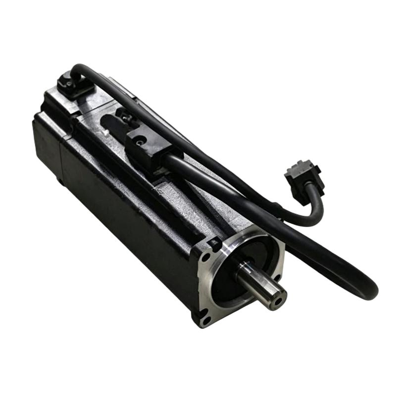
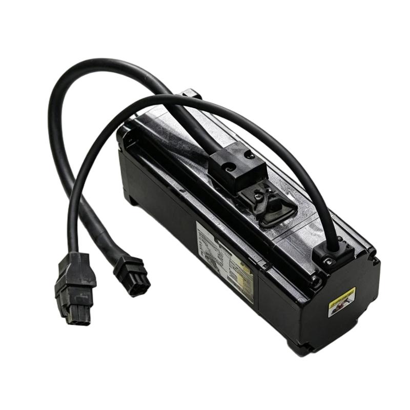
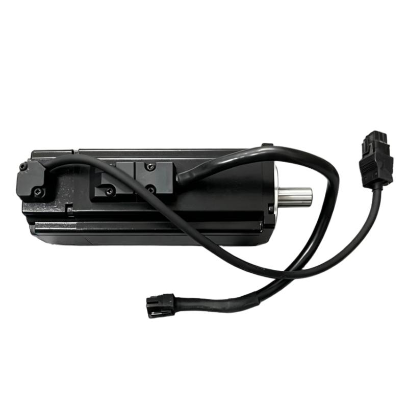
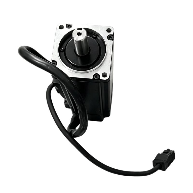
- Schneider
- BCH0602O12F1C
- Servo Motor
- France
- 166.8 mm
- 2 kg
- Xiamen, China
- New & In Stock
- T/T, PayPal, Western Union
- 1 Year
- 1-3 Working Days
- DHL, UPS, TNT, FedEx and EMS.
- 24-Hour Service
- COO
- 8
Our advantage

Global Logistics
We have a 10-year logistics and express cooperation agreement, so our products can be shipped to any place in the world.

Brand new and original
Our products are imported in bulk from the place of origin. Because of the cooperative relationship, our products are all original and 100% new.

24-hour service
We provide 7*24 hours service to our customers. We will be there whenever you need us.

Price advantage
All our products are priced very favorably because we have our own warehouse and supply.
| Company Information | |||
| [email protected] | |||
| Mobile | +8615980777398 | ||
| +8615980777398 | |||
| 15980777398 |
Product Overview
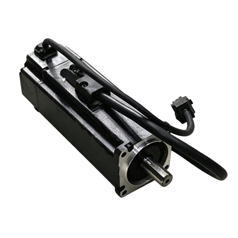
The Schneider Electric BCH0602O12F1C is a 400 W servo motor from the BCH series, used in compatible Lexium 23 Plus motion-control systems. Its 60 mm flange, keyed shaft, 20-bit incremental encoder, and integrated holding brake make it suitable for compact machinery that requires controlled rotary movement and a means of holding the axis when the motor is stationary.
In an automated packaging machine, the motor can drive a feed roller or positioning mechanism that must move through a defined distance, stop for a processing operation, and resume movement as the production sequence continues. The servo drive regulates the motor’s speed and position using encoder feedback, while the keyed shaft transfers torque through a compatible coupling or gearbox. The integrated brake adds a holding function when the axis stops, subject to the brake’s rated capacity and the machine’s requirements.
This model uses a straight connection arrangement and does not include an oil seal. These details matter when planning cable access and installing the motor near lubricated transmissions or other potential sources of contamination. Its IP40 protection rating also calls for a suitable installation environment, particularly where moisture or airborne contaminants may be present.
Technical Specifications
| Parameter | Specification |
|---|---|
| Brand | Schneider Electric |
| Model | BCH0602O12F1C |
| Product Type | Servo Motor |
| Product Series | BCH |
| Compatible Product Range | Lexium 23 Plus |
| Motor Type | Synchronous Servo Motor |
| Continuous Output Power | 0.4 kW (400 W) |
| Rated Supply Voltage | 220 V AC |
| Supply Configuration | Single-phase supply for the compatible servo drive |
| Rated Speed | 3000 rpm |
| Maximum Mechanical Speed | 5000 rpm |
| Rated Torque | 1.27 N·m |
| Peak Stall Torque | 3.82 N·m |
| Continuous Stall Current | 2.6 A |
| Shaft Configuration | Keyed shaft |
| Shaft Diameter | 14 mm |
| Shaft Length | 24 mm |
| Encoder Type | 20-bit incremental encoder |
| Holding Brake | With holding brake |
| Oil Seal | Without oil seal |
| Motor Flange Size | 60 mm |
| Electrical Connection | Straight connection |
| Cooling Method | Natural convection |
| Protection Rating | IP40 |
| Length | 166.8 mm |
| Weight | 2 kg |
Product Features
400 W motor output: The motor’s power class suits compact industrial axes requiring controlled acceleration, repeated positioning, and coordinated movement. Final sizing should account for the load’s torque demand throughout the operating speed range.
Integrated holding brake: The brake helps hold the motor shaft when engaged. It is useful for applications that need to maintain a position while the motor is stopped, but it should not be treated as a dynamic stopping brake or a safety-rated holding device.
20-bit incremental encoder: Encoder feedback supplies motor-position information to the compatible servo drive. This supports closed-loop regulation of speed and position during programmed movement.
Keyed shaft interface: The keyed shaft provides a defined mechanical connection for compatible couplings, pulleys, and gearboxes. Correct key engagement and alignment help limit vibration and unnecessary shaft loading.
60 mm mounting flange: The flange format suits compact automation equipment. When installing the motor in an existing machine, the mounting pattern and available clearance must match the complete motor assembly.
Straight electrical connection: The connection orientation affects cable routing and the clearance required around the motor. This should be considered when laying out the machine frame and nearby components.
No oil seal: The motor does not include an oil seal at the shaft. The surrounding machine design should prevent lubricants and contaminants from reaching areas that require protection.
Working Principle
The BCH0602O12F1C operates through a compatible servo drive that regulates the electrical current supplied to the motor windings. The motor converts this electrical input into rotary movement, while its incremental encoder returns feedback that the drive uses to control the commanded motion.
For example, an indexing mechanism may need to rotate a fixture to a precise position before a component is assembled. The controller issues the movement command, the drive regulates acceleration and deceleration, and encoder feedback helps the system track the motor’s response. Once the movement is complete, the controller can coordinate the next production step. When the motor reaches a suitable standstill condition, the holding brake can engage according to the configured brake sequence.
The brake and servo-control functions have different purposes. The servo drive controls movement during operation, while the holding brake maintains the shaft’s position when applied. Brake timing must be coordinated with the drive so that the motor does not attempt to move against an engaged brake.
The keyed shaft transfers torque to the connected transmission. Actual positioning performance depends on the complete axis, including drive configuration, load inertia, coupling alignment, transmission backlash, and motion settings.
Role in a Lexium 23 Plus Motion Control Architecture
The BCH0602O12F1C serves as the rotary actuator in a servo axis. A PLC or motion controller determines the required movement, the compatible Lexium 23 Plus servo drive regulates motor output, and the encoder supplies feedback. The integrated brake provides an additional holding function when the motor is stationary and the brake is engaged.
| System Component | Function | Relationship to BCH0602O12F1C |
|---|---|---|
| PLC or Motion Controller | Generates movement commands and coordinates machine sequences | Specifies target positions, speeds, and motion timing |
| Lexium 23 Plus Servo Drive | Regulates motor current and movement | Supplies controlled electrical power and processes encoder feedback |
| BCH0602O12F1C Servo Motor | Converts electrical energy into rotary motion | Drives the connected mechanical axis |
| 20-bit Incremental Encoder | Measures motor movement | Supplies position feedback for closed-loop control |
| Integrated Holding Brake | Holds the shaft when engaged | Helps prevent unintended movement while the motor is stationary |
| Keyed Shaft Coupling | Transfers motor torque | Connects the keyed shaft to a compatible transmission |
| Gearbox or Belt Drive | Adapts speed and torque | Transfers motor rotation to the machine mechanism |
| Home and Limit Sensors | Detect reference positions and travel limits | Provide additional position signals to the controller |
| HMI or Operator Panel | Displays machine status and alarms | Presents operating information through the control system |
Industrial Applications
| Application | Motion Requirement | Use of BCH0602O12F1C |
|---|---|---|
| Packaging Machinery | Repeated feeding, positioning, and controlled stops | Drives feed rollers or positioning mechanisms coordinated with the production cycle |
| Indexing Tables | Rotation between defined work stations | Moves a fixture through a compatible mechanical transmission |
| Automated Assembly | Repeatable movement between assembly positions | Operates a servo axis synchronized with assembly operations |
| Labeling Equipment | Coordinated feed and material positioning | Drives a roller or positioning mechanism under servo control |
| Inspection Stations | Accurate fixture positioning during measurement | Moves a component or fixture and holds its position when required |
| Small Material-Handling Systems | Controlled rotary movement with stationary intervals | Drives a suitable belt, pulley, or gearbox arrangement |
| Compact Production Cells | Motion coordinated with sensors and PLC logic | Functions as a servo axis with encoder feedback and a holding brake |
Installation and Maintenance
- Verify the complete model reference: Confirm that the motor is BCH0602O12F1C and that its keyed shaft, encoder, holding brake, and straight connection arrangement match the application.
- Check servo-drive compatibility: Verify the drive’s supported motor configuration, power rating, current capacity, feedback interface, and brake-control requirements.
- Confirm the electrical supply arrangement: Connect the motor through a compatible servo drive. Do not connect the motor directly to the AC mains supply.
- Inspect the mounting interface: Verify the 60 mm flange, mounting-hole alignment, fasteners, and clearance around the motor body and brake assembly.
- Align the shaft coupling: Use a coupling compatible with the keyed shaft. Check key engagement and alignment, and avoid excessive axial or radial loading.
- Evaluate the mechanical load: Compare the required torque, speed, acceleration, and load inertia with the motor and drive capabilities across the intended operating cycle.
- Protect the shaft from contamination: Since the motor has no oil seal, prevent lubricant and other contaminants from reaching the shaft area where they could affect the motor or its bearings.
- Observe the IP40 protection limit: Install the motor in a suitable environment and provide additional enclosure protection where moisture, water spray, or conductive dust may be present.
- Route power and encoder cables correctly: Follow the drive’s grounding, shielding, and cable-separation requirements to reduce electrical interference and protect feedback signals.
- Configure the holding brake: Set the brake-control sequence according to the compatible drive and application. Verify that the brake releases before commanded movement and engages at the intended point in the stopping sequence.
- Test the axis under controlled conditions: Begin at low speed and verify rotation direction, positioning response, brake operation, stopping behavior, and mechanical clearance before normal production.
- Inspect the motor periodically: Check mounting fasteners, coupling alignment, cable condition, vibration, temperature, and brake operation. Isolate the equipment and follow electrical safety procedures before performing maintenance.
Related Components
| Component | Function | Selection Considerations |
|---|---|---|
| Lexium 23 Plus Servo Drive | Controls motor current, speed, and movement | Motor compatibility, current rating, feedback interface, and brake-control support |
| PLC or Motion Controller | Generates movement commands and machine sequences | Required motion functions, I/O, and communication interface |
| Servo Power Cable | Connects the motor to the drive | Current capacity, cable length, routing, and connection compatibility |
| Encoder Feedback Cable | Carries feedback signals to the drive | Feedback interface, shielding, and cable routing |
| Brake Connection Wiring | Connects the motor’s holding brake to the control arrangement | Correct wiring, polarity, and compatible brake-control circuit |
| Keyed Shaft Coupling | Transfers torque to the driven mechanism | Shaft dimensions, key engagement, alignment, and allowable torque |
| Gearbox | Adapts speed and torque | Gear ratio, backlash, rated torque, and positioning requirements |
| Home or Limit Sensors | Detect reference positions and travel limits | Sensor type, switching logic, and controller compatibility |
Recommended Related Models
| Model | Product Description | Application Context |
|---|---|---|
| BCH0602O12A1C | Lexium 23 Plus BCH Servo Motor, 400 W class, without holding brake | Compare when the application does not require an integrated holding brake |
| BCH0601O12F1C | Lexium 23 Plus BCH Servo Motor, 200 W class, with holding brake | Consider for a lower-power application requiring a holding brake |
| BCH0602O12F1C | Lexium 23 Plus BCH Servo Motor, 400 W class, with holding brake | Reference configuration for a keyed shaft and integrated holding brake |
| BCH0801O12F1C | Lexium 23 Plus BCH Servo Motor, higher frame-size class, with holding brake | Compare where the load or mounting requirements call for a different motor frame; verify ratings and interfaces |
These models differ in power, frame size, and brake configuration. Confirm the complete order code, motor ratings, shaft arrangement, encoder interface, and servo-drive compatibility before choosing an alternative.
Key Advantages
- 400 W output class: Supports controlled movement in compact industrial automation axes.
- Integrated holding brake: Adds a holding function for applications that require the shaft to remain stationary when the motor is stopped.
- Encoder-based control: Supports closed-loop speed and position regulation.
- Keyed shaft connection: Provides a defined mechanical interface for compatible couplings and transmissions.
- Lexium 23 Plus integration: Fits motion-control systems using compatible BCH servo motors and drives.
Technical FAQs
What is the difference between BCH0602O12F1C and BCH0602O12A1C?
Both belong to the 400 W BCH0602 motor class and use a keyed shaft configuration. The key distinction is the brake configuration: BCH0602O12F1C includes a holding brake, whereas BCH0602O12A1C does not. The choice depends on whether the application requires a brake to hold the stationary axis.
Can the integrated holding brake be used to stop the motor during normal operation?
The holding brake is intended to hold the shaft at standstill, not to serve as the normal dynamic stopping mechanism. The servo drive should control deceleration, and the brake should engage according to the appropriate control sequence.
Why does this model have a greater overall length than the version without a brake?
The holding-brake assembly adds to the motor’s overall length. This model has a supplied length of 166.8 mm, so mounting clearance and nearby components should be checked when replacing a shorter motor configuration.
What should be considered when installing this motor near a gearbox?
Check shaft-coupling compatibility, alignment, torque requirements, and the potential exposure to gearbox lubricant. Since this motor has no oil seal, the mechanical assembly should prevent lubricant from reaching the motor shaft area.