

ProductPRODUCT
Featured products
Contact Us
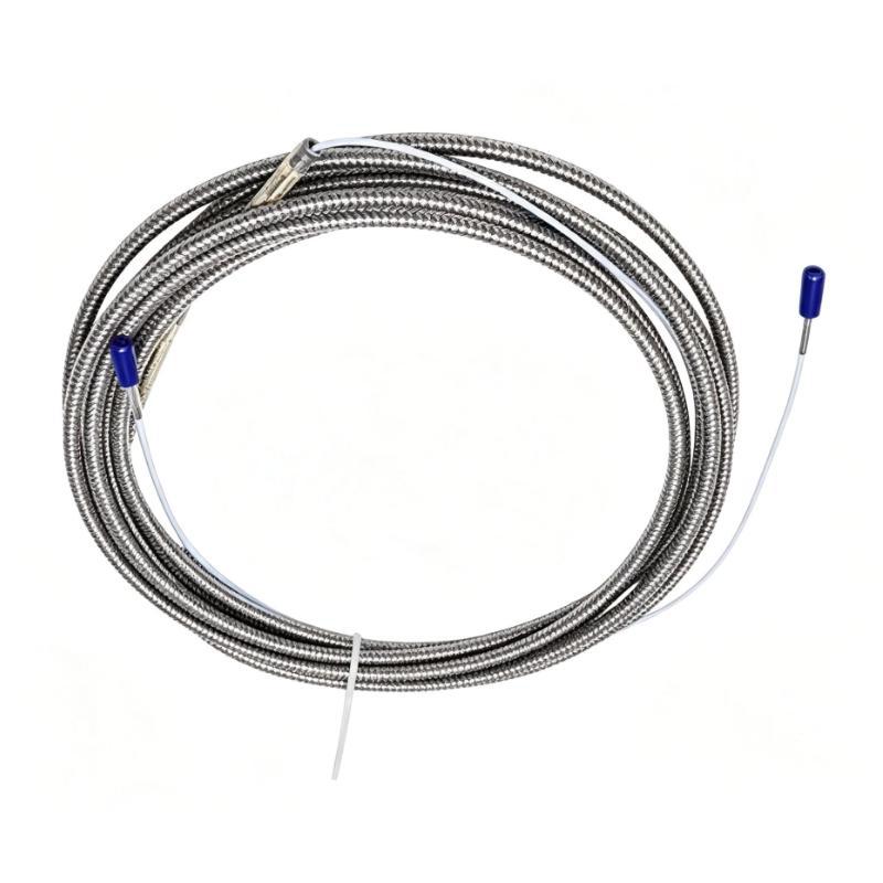
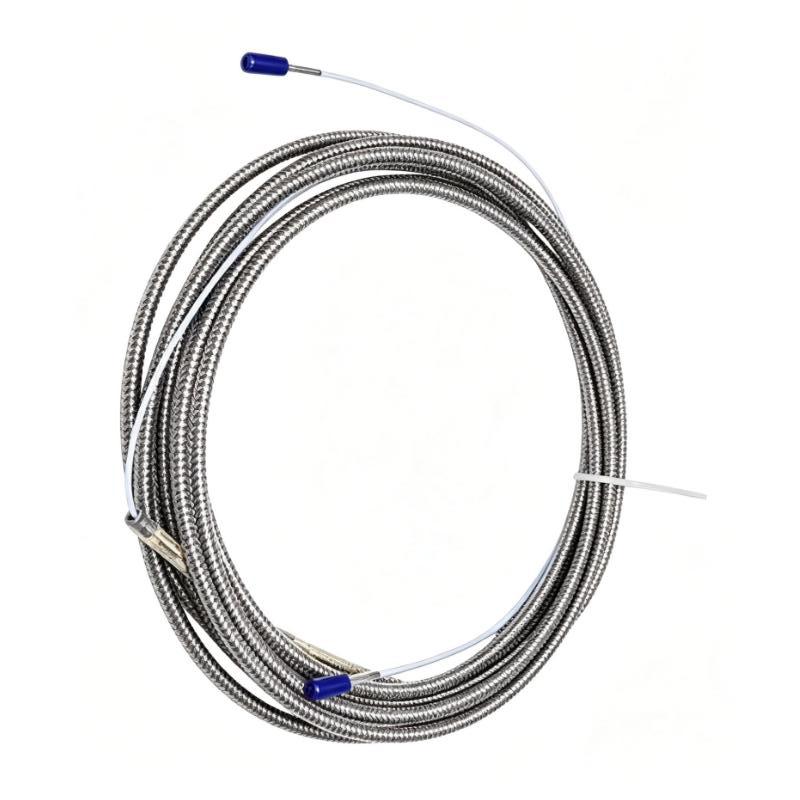
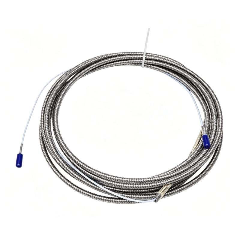
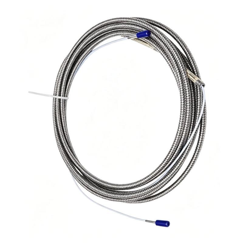
- Bently Nevada
- 84510-65
- Standard or Armored 22 AWG Cable
- USA
- 65 feet
- 3 kg
- Xiamen, China
- New & In Stock
- T/T, PayPal, Western Union
- 1 Year
- 1-3 Working Days
- DHL, UPS, TNT, FedEx and EMS.
- 24-Hour Service
- COO
- 9
Our advantage

Global Logistics
We have a 10-year logistics and express cooperation agreement, so our products can be shipped to any place in the world.

Brand new and original
Our products are imported in bulk from the place of origin. Because of the cooperative relationship, our products are all original and 100% new.

24-hour service
We provide 7*24 hours service to our customers. We will be there whenever you need us.

Price advantage
All our products are priced very favorably because we have our own warehouse and supply.
| Company Information | |||
| [email protected] | |||
| Mobile | +8615980777398 | ||
| +8615980777398 | |||
| 15980777398 |
Product Overview
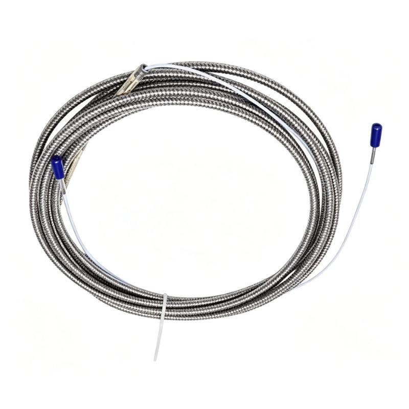
The Bently Nevada 84510-65 is a 65-foot armored instrumentation cable from the 84510 cable family, used with Bently Nevada Seismoprobe velocity transducers. Its construction consists of two shielded 22 AWG conductors, a two-socket female connector at one end, and terminal lugs at the other. This arrangement connects a compatible transducer to the associated monitoring equipment without requiring the same connector style at both ends.
The cable is relevant to machinery condition monitoring applications where vibration is measured at a bearing housing, machine casing, or structural mounting point. Bently Nevada 9200 Seismoprobe transducers measure absolute casing vibration, while the 74712 is the high-temperature version of the 9200. The cable provides the electrical connection needed to carry the transducer output into the monitoring circuit.
The armored construction is particularly relevant when the cable route needs additional mechanical protection. On a compressor skid, pump assembly, or other rotating-machine installation, the cable may pass between a field-mounted transducer and a monitoring cabinet. Its 65-foot length gives the installer a defined cable run, while the connector and terminal-lug arrangement determines how it interfaces with the connected equipment.
When replacing an existing cable, the important details are the 84510 cable family, the 22 AWG shielded two-conductor construction, the armored jacket, and the connection arrangement at each end. Matching these details helps preserve the intended signal path between the transducer and monitoring system.
Technical Specifications
| Parameter | Specification |
|---|---|
| Manufacturer | Bently Nevada |
| Model | 84510-65 |
| Product Type | Standard or Armored 22 AWG Cable |
| Cable Construction | Two-conductor, shielded, armored cable |
| Conductor Gauge | 22 AWG (0.5 mm²) |
| Cable Length | 65 feet |
| Transducer-End Connection | Two-socket female connector |
| Equipment-End Connection | Terminal lugs |
| Minimum Cable Length | 3 feet |
| Maximum Cable Length | 70 feet |
| Typical Compatible Transducers | Bently Nevada 9200 and 74712 Seismoprobe Velocity Transducers |
| Shipping Weight | 3 kg |
Product Features
- Shielded two-conductor construction: Carries the electrical output from a compatible two-wire velocity transducer.
- 22 AWG conductors: Uses the specified 22 AWG (0.5 mm²) conductor size for this cable family.
- Armored cable construction: Adds a mechanical protection layer around the shielded cable.
- Different connection styles at each end: A two-socket female connector mates with the designated transducer connection, while terminal lugs connect at the equipment end.
- 65-foot cable length: Supports installations requiring a longer cable run between the field transducer and the monitoring equipment.
- Seismoprobe system application: Associated with Bently Nevada 9200 and 74712 velocity transducers.
- Defined length range: The 84510 cable family is specified for lengths from 3 to 70 feet.
Working Principle
The 84510-65 carries the electrical output of a compatible Seismoprobe velocity transducer to the connected monitoring circuit. The transducer uses moving-coil technology to generate a voltage proportional to vibration velocity. The cable forms the electrical path between the transducer connector and the terminal-lug connection at the other end.
The signal path can be represented as:
9200 or 74712 Seismoprobe Transducer → 84510-65 Cable → Monitoring Equipment
When the transducer is mounted on a machine casing or bearing housing, mechanical vibration produces an electrical output. The shielded cable carries that output toward the monitoring equipment, where the signal can be used for vibration measurement and condition assessment. The cable itself does not measure vibration or process the signal; those functions belong to the transducer and monitoring equipment.
The armor serves a different purpose from the electrical shield. The shield helps reduce the effect of electrical interference on the signal path, while the armor adds mechanical protection to the cable assembly. Correct termination, appropriate routing, and compatibility with the installed transducer and monitor remain necessary for proper operation.
Role in a Bently Nevada Seismoprobe Vibration Monitoring System
The 84510-65 acts as the interconnecting cable between a compatible Seismoprobe velocity transducer and the associated monitoring equipment. It links the field measurement point to the receiving circuit while accommodating the different connection arrangements at the transducer and equipment ends.
| System Component | Function |
|---|---|
| Bently Nevada 9200 Seismoprobe | Measures absolute casing or structural vibration using moving-coil technology |
| Bently Nevada 74712 Seismoprobe | High-temperature version of the 9200 velocity transducer |
| 84510-65 Cable | Carries the transducer output through a shielded, armored two-conductor cable |
| Monitoring Equipment | Receives the transducer signal for vibration measurement |
| Terminal Connection | Provides the cable termination at the monitoring-equipment end |
The cable selection must match the installed transducer connector and the receiving equipment’s wiring arrangement. The cable length and route should also be considered when installing or replacing a connection in an existing monitoring system.
Industrial Applications
| Application | Typical Use |
|---|---|
| Compressor Monitoring | Connecting a compatible Seismoprobe transducer to vibration monitoring equipment |
| Pump and Motor Monitoring | Carrying casing-vibration signals from a field measurement point |
| Turbomachinery Monitoring | Providing a cable connection between a compatible velocity transducer and its monitoring circuit |
| Industrial Rotating Equipment | Connecting vibration measurement points on machine casings or bearing housings |
| High-Temperature Machinery Areas | Supporting a 74712-based installation when the complete cable route and termination arrangement are suitable for the application |
| Maintenance and Replacement | Replacing an existing 84510 cable while retaining the specified connector arrangement and cable length |
Installation and Maintenance
- Verify the cable part number: Confirm that 84510-65 matches the cable required by the installed monitoring arrangement.
- Identify the transducer model: Check whether the connected instrument is a compatible 9200 or 74712 Seismoprobe velocity transducer.
- Inspect both cable ends: Confirm that the two-socket female connector and terminal-lug arrangement match the intended connection points.
- Check the cable length: Confirm that the 65-foot cable accommodates the complete route without excessive tension or improvised extensions.
- Inspect the armored jacket: Look for crushing, cuts, deformation, or damage that could compromise the cable’s physical protection.
- Route the cable carefully: Keep the cable clear of moving machinery, sharp edges, and locations where repeated contact could damage the assembly.
- Secure the cable run: Support the cable appropriately and prevent its weight from pulling on the transducer connector or equipment terminals.
- Check the connector interface: Ensure that the female connector matches the transducer’s designated connection and is properly seated.
- Verify terminal-lug connections: Check conductor identification and terminal placement against the applicable equipment wiring arrangement.
- Inspect the signal path: If the monitoring system shows an abnormal reading, examine the cable, connectors, terminations, and transducer before attributing the issue to the monitor.
- Compare the replacement specification: Confirm conductor gauge, shielding, armored construction, length, and connector arrangement before installing a substitute cable.
- Document the installed connection: Record the cable reference, transducer location, receiving equipment, and routing details for future troubleshooting.
Related Components
| Model / Component | Product Type | Function |
|---|---|---|
| Bently Nevada 9200 | Seismoprobe Velocity Transducer | Measures absolute casing or structural vibration |
| Bently Nevada 74712 | High-Temperature Seismoprobe Velocity Transducer | Measures vibration in applications requiring the high-temperature transducer version |
| Bently Nevada 3300 Monitoring System | Machinery Monitoring System | Part of the Bently Nevada monitoring product family used in machinery condition monitoring |
| Bently Nevada 3500 Monitoring System | Machinery Protection and Monitoring System | Receives monitoring inputs as configured for the installed system |
| Bently Nevada 00531061 | Mating Connector | Mating connector identified for the 9200 and 74712 Seismoprobe transducers |
Recommended Related Models
| Model | Product Type | Relationship to 84510-65 |
|---|---|---|
| Bently Nevada 84510-50 | Standard or Armored 22 AWG Cable | Same cable family with a shorter specified length |
| Bently Nevada 84509-65 | Armored 22 AWG Cable with Terminal Lugs at Both Ends | Related armored cable option with a different end-connection arrangement |
| Bently Nevada 84660-65 | Shielded 22 AWG Cable with Female Connector and Terminal Lugs | Related connector arrangement in the Seismoprobe interconnection cable family |
| Bently Nevada 9200 | Seismoprobe Velocity Transducer | Compatible transducer family identified for Seismoprobe cable connections |
| Bently Nevada 74712 | High-Temperature Seismoprobe Velocity Transducer | Related transducer for high-temperature vibration measurement applications |
Key Advantages
- Connects compatible Seismoprobe transducers to monitoring equipment through a defined connector arrangement.
- Uses shielded two-conductor 22 AWG cable construction.
- Armored construction adds mechanical protection along the cable route.
- The 65-foot length supports installations requiring a longer interconnection.
- The 84510 cable family has a specified length range of 3 to 70 feet.
Technical FAQs
Which Bently Nevada transducers are associated with the 84510-65 cable?
The 84510 cable family is listed for connections involving the 9200 and 74712 Seismoprobe velocity transducers. The specific connector arrangement must match the installed transducer.
Why does the 84510-65 have a female connector at one end and terminal lugs at the other?
The two ends serve different connection points. The two-socket female connector connects to the designated transducer interface, while the terminal lugs allow connection at the monitoring-equipment end according to the applicable wiring arrangement.
What is the difference between the 84510-65 and 84509-65?
Both belong to the armored 22 AWG cable family, but their end connections differ. The 84510 version has a two-socket female connector at one end and terminal lugs at the other; the 84509 version uses terminal lugs at both ends. They should not be treated as interchangeable without checking the connection requirements.
Why does cable length matter in a Seismoprobe monitoring installation?
Cable length determines whether the transducer can reach its designated monitoring connection while following the intended route. The Seismoprobe documentation also identifies lead-wire length as a factor in system frequency response at longer distances, so the installed cable length and monitoring arrangement should be considered together.