

ProductPRODUCT
Featured products
Contact Us
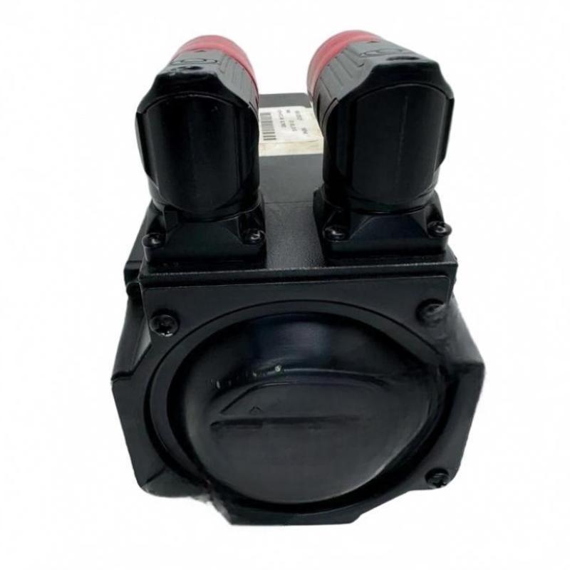
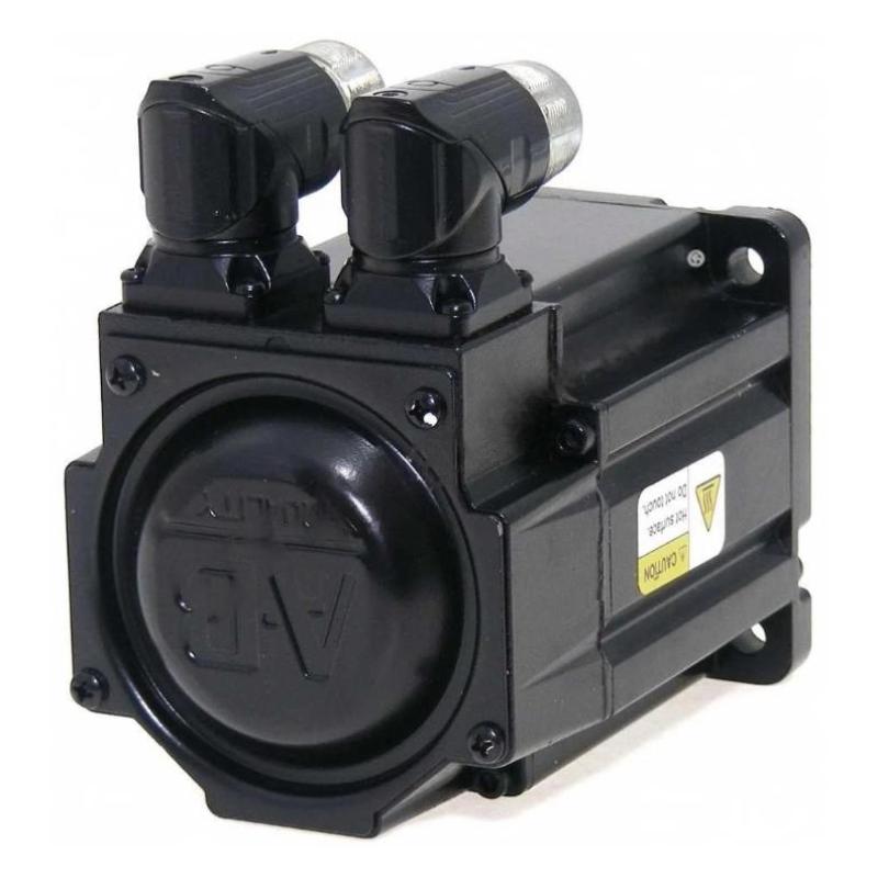
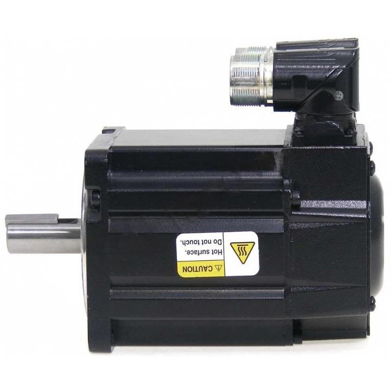
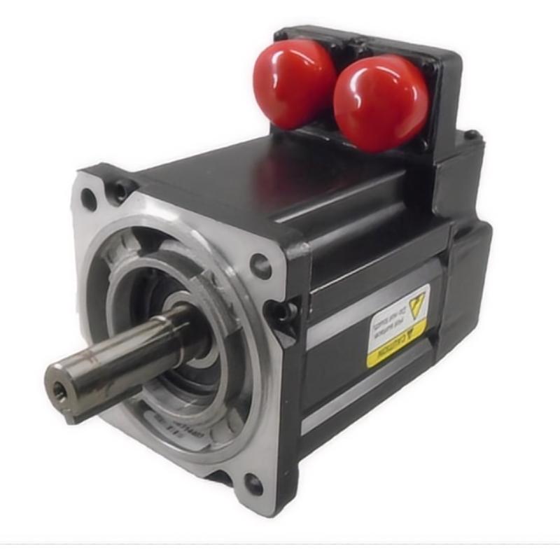
- Allen Bradley
- MPL-B310P-MJ72AH
- Servo Motor
- USA
- 100 mm
- 2.7 kg
- Xiamen, China
- New & In Stock
- T/T, PayPal, Western Union
- 1 Year
- 1-3 Working Days
- DHL, UPS, TNT, FedEx and EMS.
- 24-Hour Service
- COO
- 4
Our advantage

Global Logistics
We have a 10-year logistics and express cooperation agreement, so our products can be shipped to any place in the world.

Brand new and original
Our products are imported in bulk from the place of origin. Because of the cooperative relationship, our products are all original and 100% new.

24-hour service
We provide 7*24 hours service to our customers. We will be there whenever you need us.

Price advantage
All our products are priced very favorably because we have our own warehouse and supply.
| Company Information | |||
| [email protected] | |||
| Mobile | +8615980777398 | ||
| +8615980777398 | |||
| 15980777398 |
Product Overview
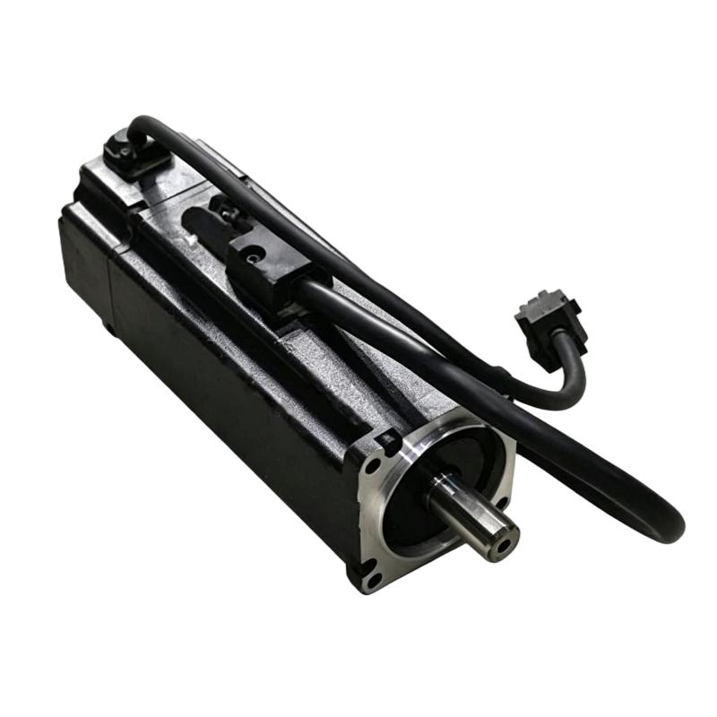
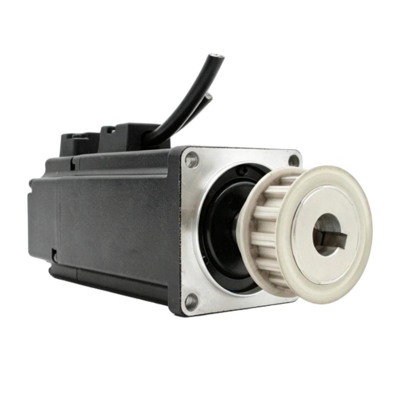
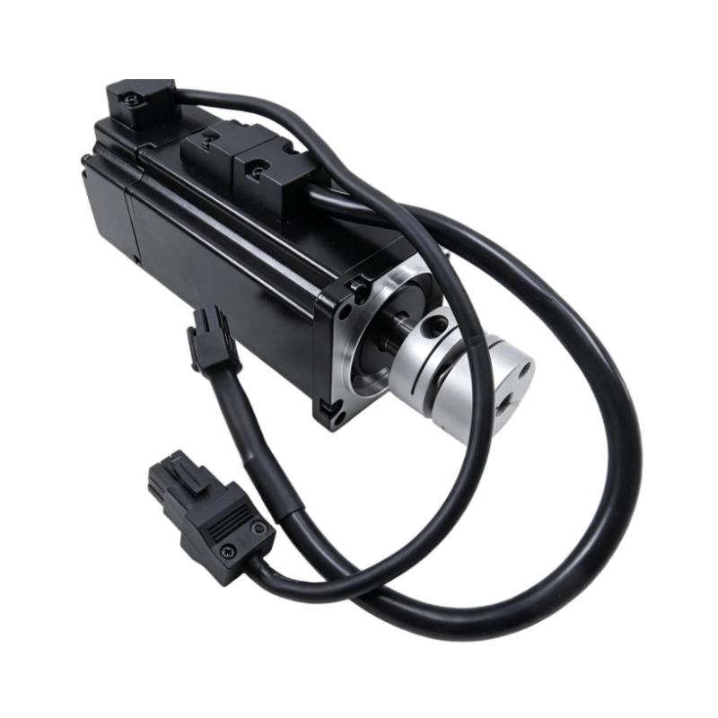
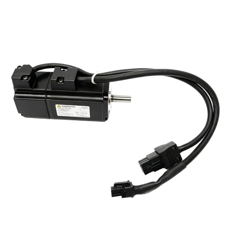
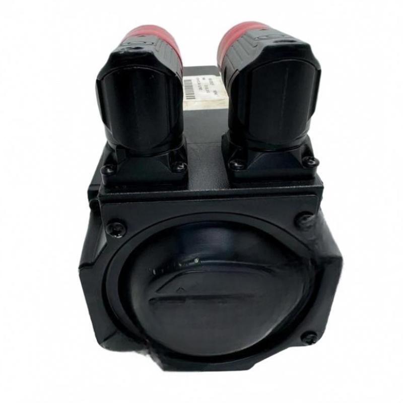
The Allen Bradley MPL-B310P-MJ72AH Servo Motor is an industrial motion-control component identified for applications requiring controlled rotary motion, accurate positioning, and coordinated operation with a compatible servo drive and automation controller. Servo motors are widely used in automated manufacturing because they enable machinery to regulate position, speed, and torque according to programmed motion commands.
In a servo system, the motor converts electrical energy into mechanical rotation. The servo drive regulates the electrical power supplied to the motor, while the motion controller generates commands based on the machine’s operating sequence. When supported by the configured feedback arrangement, the system can compare actual motion with commanded motion and make corrections to improve positioning performance.
The MPL-B310P-MJ72AH belongs to the Allen Bradley MPL servo motor model family identified in the supplied product description. Its specified frame size is 100 mm, and its listed weight is 2.7 kg. These physical characteristics are useful when planning machine layouts, checking mounting-space requirements, and arranging replacement inventory.
Selecting a servo motor requires more than matching its frame size. Motor winding, rated voltage, continuous and peak torque, speed range, feedback device, shaft configuration, connector arrangement, and drive compatibility must all be checked against the exact model documentation. The complete catalog number should therefore be confirmed before purchasing or installing a replacement.
Technical Specifications
| Parameter | Specification |
|---|---|
| Manufacturer | Allen Bradley |
| Model | MPL-B310P-MJ72AH |
| Product Type | Servo Motor |
| Product Family | MPL Servo Motor Series |
| Frame Size | 100 mm |
| Weight | 2.7 kg |
| Primary Function | Controlled rotary motion for industrial automation |
| Motion Functions | Position, speed, and torque control when used in a compatible servo system |
| Drive Requirement | Compatible servo drive selected according to motor specifications |
| Control Integration | Compatible motion controller and servo system |
| Typical Applications | Automated machinery, positioning systems, material handling, and manufacturing equipment |
| Mounting | Verify flange, shaft, and mechanical interface requirements for the exact model |
The table reflects the product identification and physical information supplied. Electrical ratings, rated torque, maximum speed, feedback type, brake configuration, shaft dimensions, and environmental ratings should be confirmed from the exact motor nameplate and technical documentation rather than inferred from the model number.
What Is the Allen Bradley MPL-B310P-MJ72AH Servo Motor?
A servo motor is designed to operate as part of a controlled motion system. Unlike a motor used only for continuous rotation, a servo motor works with a compatible drive and controller to achieve defined motion commands. These commands may specify a target position, rotational speed, acceleration profile, or torque limit.
The MPL-B310P-MJ72AH is identified as a servo motor within the Allen Bradley MPL family. In an appropriately configured machine, it can provide the mechanical movement required for positioning, indexing, synchronized motion, or other controlled rotary operations.
A typical servo system consists of several functional elements:
Motion Controller → Servo Drive → Servo Motor → Mechanical Load
A feedback device, where provided by the specific motor configuration, returns motion information to the drive or control system. The control system uses this information to regulate motor operation according to the application’s requirements.
The performance of the complete system depends on correct component selection, suitable mechanical design, accurate parameter configuration, and proper commissioning.
Function and Working Principle
1. Electrical Power Conversion
The servo drive receives electrical power from the designated supply and produces controlled motor output according to the requested motion command. The exact power arrangement and electrical ratings depend on the drive and motor combination.
The motor converts this electrical input into mechanical torque and rotation. Correct matching between the motor and drive is essential to ensure that the motor operates within its permitted electrical and thermal limits.
2. Controlled Rotary Motion
When the controller issues a motion command, the servo drive regulates motor operation to achieve the required movement. Depending on the application, the command may involve moving to a specific position, maintaining a speed, or producing a controlled amount of torque.
This capability is important in machines where movement must be coordinated with other axes, sensors, or process events.
3. Feedback and Motion Correction
Servo systems commonly use feedback to monitor motor position or speed. The feedback arrangement depends on the exact motor configuration and supported drive system.
When feedback is available, the drive can compare the measured motor state with the commanded state and adjust its output to reduce motion error. Correct feedback wiring and configuration are essential for reliable operation.
4. Acceleration and Deceleration
Industrial machines often require controlled acceleration and deceleration to prevent abrupt mechanical movement. A compatible servo drive can apply programmed motion profiles to help manage transitions between operating speeds and positions.
The achievable acceleration depends on the motor’s torque capability, the drive rating, the load inertia, mechanical transmission, and the configured motion limits.
5. Coordinated Machine Operation
In multi-axis machinery, servo motors can be coordinated by a motion controller to execute synchronized movements. This is useful for applications involving cutting, indexing, positioning, packaging, assembly, or product transfer.
The controller and drive must support the required motion architecture and communication arrangement. These capabilities should be confirmed for the specific equipment configuration.
Role in Industrial Automation Systems
The Allen Bradley MPL-B310P-MJ72AH can serve as the motor element in a compatible servo-motion installation. Its role is to produce the mechanical movement required by the machine while the associated control electronics manage the motion profile.
A typical automation architecture includes the following layers:
| System Element | Main Responsibility |
|---|---|
| PLC or Motion Controller | Executes machine logic and generates motion commands |
| Servo Drive | Regulates motor power and implements motion-control functions |
| Servo Motor | Converts electrical power into mechanical rotation |
| Feedback Device | Provides supported position or speed information when fitted |
| Mechanical Transmission | Transfers motor torque to the machine load |
| Sensors and Switches | Detect machine position, product presence, and operating conditions |
| HMI Panel | Provides operator commands, status, and diagnostic information |
| Industrial Network | Exchanges supported control and diagnostic data between devices |
The motor should be selected as part of the complete motion system rather than treated as an independent replacement component. Mechanical loading, inertia, operating duty, and required positioning performance all influence the suitability of the final configuration.
Industrial Applications
Automated Assembly Equipment
Servo motors can control rotary mechanisms used in assembly stations, indexing tables, fixtures, and automated tooling. Controlled movement helps coordinate mechanical actions with the machine’s operating sequence.
Packaging Machinery
Packaging systems often require accurate movement of feeding mechanisms, indexing units, sealing assemblies, and product-transfer equipment. Servo-based motion can help coordinate these operations when the motor and drive are correctly sized.
Material Handling
Positioning units, transfer mechanisms, and automated handling equipment may use servo motors when controlled acceleration, repeatable positioning, or coordinated motion is required.
Printing and Converting Equipment
Applications involving web handling, indexing, cutting, and synchronized rollers may use servo systems to regulate movement in accordance with process requirements. Suitability depends on torque, speed, inertia, and synchronization demands.
Industrial Robotics and Positioning Systems
Servo motors are commonly used in controlled rotary axes and positioning mechanisms. A particular motor’s suitability depends on the required dynamic performance, mechanical interface, feedback configuration, and drive compatibility.
General Manufacturing Automation
Servo systems can support machine functions that require more precise movement control than a basic motor starter or fixed-speed drive can provide. Typical examples include automated fixtures, inspection mechanisms, and programmable positioning equipment.
These are general applications of servo technology, not a guarantee that every application is suitable for the MPL-B310P-MJ72AH. Final selection should be based on verified performance data and system requirements.
Installation and Mechanical Integration
Proper installation helps protect the motor and connected machinery from misalignment, excessive vibration, and avoidable mechanical stress.
Confirm the Motor Identity
Before installation, check the complete catalog number on the motor label and compare it with the machine’s original bill of materials or maintenance records. Confirm the suffix and any revision or configuration information that applies to the installed unit.
Motors within the same family can have different electrical characteristics, feedback arrangements, shaft interfaces, and accessories. Similar appearance alone does not establish interchangeability.
Verify Frame and Mounting Dimensions
The specified frame size is 100 mm. Before fitting the motor, verify the actual mounting pattern, flange dimensions, shaft diameter, shaft length, and permitted mounting orientation.
Frame size alone does not establish that a motor will fit an existing machine. Check the mechanical drawings and the requirements of the connected gearbox, coupling, pulley, or driven mechanism.
Check Shaft Alignment
The motor shaft must be aligned correctly with the driven equipment. Misalignment can increase bearing loads, create vibration, and reduce service life.
Use the specified coupling and alignment procedure. Avoid applying excessive radial or axial force to the motor shaft during assembly.
Evaluate the Mechanical Load
Before commissioning, assess the driven load, acceleration requirements, stopping behavior, inertia, and duty cycle. The motor and drive must be suitable for both steady-state operation and transient demands.
An incorrectly sized servo system may experience excessive current, following errors, overheating, or repeated protective trips.
Electrical Installation and Drive Compatibility
Servo motors require a compatible drive and correctly configured wiring. The exact electrical arrangement for the MPL-B310P-MJ72AH must be established from its verified product specifications.
Confirm Motor and Drive Compatibility
Check that the selected servo drive supports the motor’s electrical ratings, feedback system, and required operating mode. Confirm the motor’s rated voltage, continuous current, peak current, torque characteristics, and speed limits.
Do not select a drive based solely on motor family or physical size.
Inspect Power and Feedback Connections
Before connecting the equipment, identify the designated motor power connections and any feedback, brake, or accessory connections that apply to the exact model.
Inspect connectors, cables, seals, and cable routing for damage. Incorrect wiring can cause drive faults, unstable motion, feedback errors, or hardware damage.
Apply Grounding and Noise-Control Practices
Follow the applicable installation instructions for protective grounding, cable shielding, bonding, and separation between motor power cables and sensitive signal cables.
Correct installation practices help reduce electrical interference and support stable feedback and communication performance.
Configure Motor Parameters
Enter the correct motor data in the compatible drive or motion-control environment. Parameter values must correspond to the actual motor configuration.
Where supported and required, follow the manufacturer’s prescribed motor-identification or commissioning procedure. Do not substitute estimated parameters for the motor’s documented values.
Verify Protective Measures
Confirm that emergency-stop arrangements, machine guarding, overtravel limits, and other required protective functions are implemented in the appropriate control and safety architecture.
A servo motor itself should not be assumed to provide a complete machine-safety function. Protective measures must be designed and validated for the full machine.
Commissioning Procedure
A structured commissioning process helps verify that the motor, drive, controller, and mechanical load work together correctly.
- Inspect the installation. Check mounting bolts, shaft alignment, coupling condition, cable routing, and connector security.
- Verify the configuration. Confirm the motor catalog number, drive selection, feedback arrangement, and configured motor parameters.
- Check the mechanical load. Ensure that the load can move freely within its intended operating range and that no obstruction is present.
- Review drive diagnostics. Resolve configuration, feedback, or wiring faults before enabling motion.
- Perform a controlled initial test. Follow the approved commissioning procedure and begin with conservative motion limits appropriate to the machine.
- Confirm direction of rotation. Verify that the commanded direction matches the machine design before normal operation.
- Test positioning and speed. Check motion response, repeatability, stopping behavior, and relevant operating limits.
- Monitor temperature and vibration. Observe the motor and mechanical assembly during the prescribed test period.
- Record the results. Document parameter settings, observed performance, and any corrective work completed.
Commissioning should be performed by qualified personnel using the procedures applicable to the installed drive and machine.
Troubleshooting the MPL-B310P-MJ72AH Servo Motor
When a servo system develops a fault, the investigation should cover the motor, drive, feedback circuit, mechanical load, and controller configuration.
Motor Does Not Rotate
Possible causes include a disabled drive, missing or incorrect power, an active protective fault, incorrect motor parameters, feedback problems, or a motion command that is not being executed.
Check the drive’s displayed status and diagnostic information first. Verify the control-enable conditions and confirm that the configured motor identity matches the installed unit.
Servo Drive Reports a Feedback Fault
A feedback-related fault may result from a damaged cable, loose connector, incorrect feedback configuration, electrical interference, or a fault in the feedback device.
Inspect the feedback connections and cable condition, then compare the drive configuration with the actual motor. Follow the prescribed diagnostic procedure before replacing components.
Positioning Is Inaccurate
Positioning errors may be associated with incorrect tuning, mechanical backlash, coupling slippage, load variation, feedback issues, or unsuitable motion parameters.
Review the drive diagnostics and controller command values. Inspect the mechanical transmission for looseness and verify that the load remains within the designed operating limits.
Excessive Vibration or Noise
Potential causes include shaft misalignment, loose mounting hardware, bearing wear, mechanical resonance, inappropriate tuning, or excessive load inertia.
Inspect the mechanical installation before making parameter changes. If abnormal noise persists, stop the equipment according to the maintenance procedure and investigate the source.
Motor Overheating
Motor overheating can result from excessive load, frequent acceleration, inadequate cooling, incorrect motor parameters, high ambient temperature, or operation outside the rated duty.
Compare actual operating conditions with the motor’s documented limits. Check the driven mechanism for binding and verify that the motor and drive are correctly sized for the application.
Intermittent Operation
Intermittent faults may be caused by loose electrical connections, damaged cables, unstable power, temperature-related problems, controller conditions, or mechanical disturbances.
Record the drive fault history and operating conditions when the issue occurs. A repeatable relationship between load, temperature, motion speed, and the fault can help narrow the investigation.
Maintenance Recommendations
Preventive maintenance should cover the motor and the complete servo installation.
Inspect mechanical mounting: Check mounting bolts, couplings, shaft alignment, and signs of abnormal vibration.
Examine cables and connectors: Look for damaged insulation, loose connections, contamination, and mechanical strain.
Monitor operating behavior: Record recurring faults, unusual noise, temperature changes, and deviations in positioning performance.
Maintain the surrounding environment: Keep the installation within its specified temperature and contamination limits, and maintain any required cooling arrangements.
Review drive diagnostics: Use available fault histories and operating information to identify recurring problems.
Protect the feedback system: Avoid unnecessary handling of feedback connectors and follow the prescribed procedures when servicing cables or replacing components.
Document maintenance work: Record the motor identity, drive configuration, parameter changes, and commissioning results after repairs or replacement.
Maintenance intervals should reflect the manufacturer’s instructions, machine duty cycle, environmental conditions, and the consequences of an unexpected stoppage.
Compatible System Components
The MPL-B310P-MJ72AH should be integrated with components selected for the exact motor configuration and machine requirements.
| Component | Function |
|---|---|
| Compatible Allen Bradley Servo Drive | Supplies and regulates motor power |
| PLC or Motion Controller | Generates motion commands and machine sequencing |
| Motor Power Cable | Connects the motor to the compatible drive |
| Feedback Cable | Carries supported feedback signals when applicable |
| Coupling or Mechanical Transmission | Transfers motor rotation to the load |
| Gearbox, if required | Adapts speed and torque to the driven mechanism |
| HMI Panel | Provides operating status and diagnostic displays |
| Industrial Network | Supports communication when required by the system architecture |
| Protective Devices | Provide the electrical and machine protection required by the design |
The exact drive, cable, feedback accessory, and controller part numbers must be selected only after confirming the motor’s complete specifications. A component that works with another MPL motor may not necessarily be suitable for this particular variant.
Replacement and Procurement Considerations
When sourcing a replacement Allen Bradley MPL-B310P-MJ72AH servo motor, compare the full model number and mechanical and electrical requirements with the original installed unit.
Key checks include:
- Exact catalog number and suffix
- Frame size and mounting arrangement
- Shaft dimensions and mechanical interface
- Rated and peak torque requirements
- Rated voltage and current
- Speed and duty-cycle requirements
- Feedback configuration
- Brake or accessory requirements, if applicable
- Compatibility with the existing servo drive
- Physical condition and applicable inspection records
The specified 100 mm frame size and 2.7 kg weight are useful for preliminary mechanical planning and shipping preparation. They are not sufficient on their own to confirm compatibility.
If the original motor is no longer available, an alternative should be selected by comparing verified torque-speed performance, mounting dimensions, feedback requirements, and drive support. Any proposed substitute should be validated before being placed into service.
Key Advantages of Servo Motor Technology
Controlled Motion
A compatible servo system can execute defined position, speed, and torque commands to support repeatable machine movement.
Integration with Automated Machinery
Servo motors can work with suitable drives and controllers to coordinate movement with sensors, process events, and other machine axes.
Flexible Motion Profiles
The drive and controller can implement application-specific acceleration, deceleration, and movement profiles within the system’s operating limits.
Support for Automated Positioning
Servo-based motion is suitable for mechanisms where controlled rotary movement and feedback-based correction are required.
Compact Physical Characteristics
The listed frame size of 100 mm and weight of 2.7 kg provide useful reference information for equipment layout, handling, and replacement planning.
Technical FAQs
What is the Allen Bradley MPL-B310P-MJ72AH?
It is identified as an Allen Bradley MPL-series servo motor designed for use in a compatible industrial motion-control system.
What is the frame size of this motor?
The supplied frame size is 100 mm.
How much does the MPL-B310P-MJ72AH weigh?
The supplied weight is 2.7 kg.
What does a servo motor do in an automation system?
A servo motor converts electrical energy into mechanical movement. When connected to a compatible drive and controller, it can support controlled position, speed, and torque operation.
Which servo drive should be used with this motor?
The drive must be selected according to the motor’s verified electrical ratings, feedback configuration, torque and speed requirements, and the supported controller architecture. Confirm the exact combination before installation.
Can this motor replace another MPL-series motor?
Not automatically. Motors in the same product family may differ in winding, feedback, shaft configuration, brake arrangement, and performance ratings. Confirm the complete model number and all relevant specifications before replacement.
What causes servo-motor positioning errors?
Potential causes include feedback faults, incorrect configuration, mechanical backlash, coupling slippage, unsuitable tuning, or a load that exceeds the system’s design requirements.
What should be checked before installing a replacement?
Verify the motor’s full catalog number, frame and shaft dimensions, electrical ratings, feedback arrangement, drive compatibility, and mechanical load requirements. Complete the required commissioning tests before returning the machine to normal operation.
Conclusion
The Allen Bradley MPL-B310P-MJ72AH Servo Motor is identified as an MPL-series motion-control component for compatible industrial automation applications. Used with an appropriately selected servo drive and controller, a servo motor can provide controlled rotary movement for positioning, machine sequencing, and coordinated manufacturing operations.
With a specified 100 mm frame size and a listed weight of 2.7 kg, the motor’s physical characteristics are useful for equipment planning and replacement logistics. Reliable performance depends on correct motor-drive matching, suitable mechanical installation, accurate parameter configuration, sound feedback connections, and systematic commissioning.
Before purchasing or installing the MPL-B310P-MJ72AH, verify the complete catalog number and the motor’s electrical and mechanical specifications. Careful component selection and documented testing help ensure that the servo system operates within its intended limits and delivers dependable motion control.