
NewsNEWCENTER
Featured products
Contact Us
Emerson VE6006 Media Converter Installation Guide
2026-10-10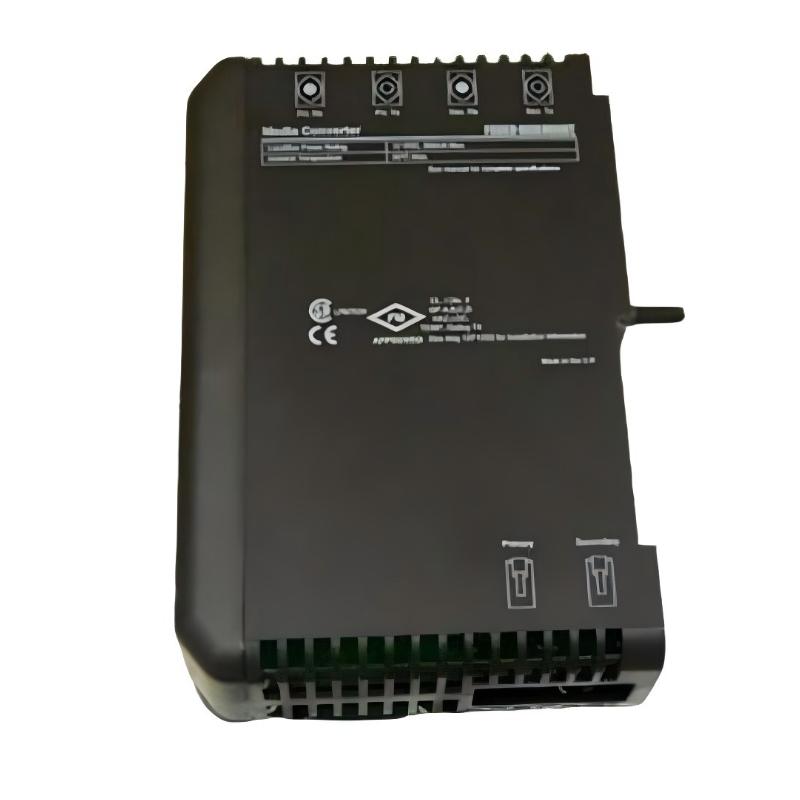
The Emerson VE6006 Media Converter installation process should focus on hardware identification, interface compatibility, communication wiring, network configuration, and system-level commissioning. In industrial automation environments, media conversion equipment helps connect communication interfaces that use different physical transmission media. Before installing the VE6006, verify its exact product identification and intended function within the installed Emerson control system, as interface types, port assignments, and supported communication standards must be confirmed from the applicable equipment documentation.
Emerson VE6006 Media Converter Overview
Industrial media conversion is used to maintain communication between automation devices when their physical communication interfaces or transmission media differ. Depending on the specific hardware design, a media converter may connect copper-based communication cabling with an optical fiber link or provide another form of physical-layer interface conversion.
In a typical industrial communication architecture, the connection path may resemble the following:
Industrial Controller
        ↓
Communication Interface
        ↓
Media Conversion Device
        ↓
Compatible Communication Medium
        ↓
Remote Controller / Network Device
        ↓
Supervisory System
This diagram illustrates a general media-conversion architecture, not a confirmed port diagram for the VE6006. Confirm the actual interface types and intended network role before connecting the device.
Installation Preparation for Emerson VE6006
Before installation, confirm that the VE6006 matches the communication requirements of the intended application. A physical connector that fits does not necessarily guarantee electrical or protocol compatibility.
- Verify the complete VE6006 model identification and hardware revision.
- Confirm the intended installation location and system role.
- Identify the communication interfaces on both sides of the connection.
- Check the required cable types, connectors, and transmission distance.
- Confirm power requirements if the device requires a separate supply.
- Review grounding and shielding requirements.
- Inspect the housing, ports, and connectors for damage.
- Record the existing network connections before making changes.
- Arrange an approved maintenance window if installation may interrupt control communications.
Emerson VE6006 Mechanical Installation
Install the device in its designated cabinet, rack, or mounting location according to the applicable installation instructions. Ensure that connectors remain accessible and that cables can be routed without excessive bending, tension, or mechanical stress.
Cabinet and Environmental Considerations
- Use a secure mounting arrangement appropriate to the device design.
- Keep communication cables organized and clearly labeled.
- Maintain adequate clearance for connector access and maintenance.
- Protect the device from moisture, conductive dust, and excessive vibration.
- Keep communication wiring away from strong electrical interference sources where practical.
- Follow the control cabinet’s grounding and environmental requirements.
VE6006 Communication Wiring and Interface Integration
Correct interface matching is essential for reliable communication. Before connecting the Emerson VE6006, confirm the physical layer, connector type, cable specification, and transmission requirements of each connected device.
Communication Cable Inspection
Inspect the cable for crushed sections, damaged insulation, contaminated connectors, and excessive bending. For optical fiber connections, where applicable, check connector cleanliness and use compatible fiber types and optical interfaces. Avoid looking directly into an optical transmitter or an energized fiber connector.
Connection Verification
- Match each cable to the intended interface.
- Verify transmit and receive orientation where the interface requires it.
- Confirm that connectors are fully seated and secured.
- Keep cable labels consistent with the system drawings.
- Check that the connected devices use compatible communication settings.
- Avoid making assumptions about port functions based on connector appearance alone.
Emerson VE6006 Setup and Configuration
Configuration requirements depend on the actual VE6006 hardware and the surrounding communication system. Some physical-layer media converters operate transparently without extensive software configuration, while other communication devices may require interface settings or network parameters. Confirm the applicable requirements for this specific model before commissioning.
- Confirm the device’s intended communication function.
- Verify power and interface requirements.
- Check the connected devices’ communication settings.
- Confirm that the selected cables and interfaces are compatible.
- Review the network topology and connection records.
- Check available status indicators or diagnostic information.
- Confirm that the control system recognizes the expected communication path.
Emerson VE6006 Commissioning Procedure
Commissioning should establish a reliable connection without introducing unnecessary changes to the existing control network.
Device Identification
        ↓
Physical Installation
        ↓
Cable and Interface Verification
        ↓
Power Verification
        ↓
Link / Status Inspection
        ↓
Communication Test
        ↓
Controller and Network Validation
        ↓
Operational Monitoring
Step 1: Verify the Physical Connections
Inspect all connected interfaces and confirm that the cable arrangement matches the approved drawings. Check that all connectors are secure and that the device is installed in the intended location.
Step 2: Check Power and Status
If the device requires power, verify that the supply meets its specified requirements. Inspect any available status indicators and compare them with the equipment documentation. Do not interpret an indicator as a specific fault code unless its meaning has been confirmed.
Step 3: Test Communication
Use approved network diagnostics or controller communication status information to determine whether the expected connection is operating. Where possible, compare communication performance before and after installation.
Step 4: Validate the Control Application
Confirm that connected controllers, operator stations, and supervisory systems can exchange the required data. A physical link indication alone does not prove that all application-level communications are functioning correctly.
VE6006 Installation Validation Checklist
- Correct device identification confirmed.
- Intended communication function verified.
- Mounting secure and environmental conditions acceptable.
- Power requirements checked where applicable.
- Interface and cable compatibility confirmed.
- Connectors securely installed.
- Communication status checked.
- Controller and network communication tested.
- Control-system operation validated.
- Final wiring and network records updated.
Representative Emerson VE6006 Commissioning Case
Consider a representative industrial network installation in which a remote control device cannot communicate after a media conversion component is installed. Initial inspection confirms that power is available, but the network connection remains inactive.
The technician verifies the interface types at both ends, inspects the cable connectors, and compares the physical connections with the system drawings. The inspection identifies an incompatible cable interface. After the correct cable arrangement is installed, the link becomes available and communication testing can continue.
This illustrative case shows why physical compatibility should be verified before investigating more complex controller or application faults.
Emerson VE6006 Installation FAQs
What should be checked before installing the VE6006?
Confirm the complete model identification, intended function, interface types, cable requirements, power requirements, and compatibility with the surrounding control network.
Does a media converter always require software configuration?
No. Configuration requirements depend on the device design. Some media converters work transparently, while other communication devices require additional settings. Verify the requirements for the exact VE6006 model.
Why is a physical link not enough to confirm successful commissioning?
A physical link indicates that an interface may be connected, but it does not necessarily confirm correct communication settings or successful data exchange with the control application.
Can any communication cable be used if the connector fits?
No. Cable type, interface characteristics, transmission requirements, and connector configuration must all be compatible.
Technical Summary
Reliable installation of the Emerson VE6006 Media Converter depends on accurate hardware identification, compatible communication interfaces, correct cable selection, secure installation, and systematic commissioning. Verifying the physical connection and then testing the complete communication path helps reduce network interruptions and improves confidence in industrial control system integration.