

ProductPRODUCT
Featured products
Contact Us
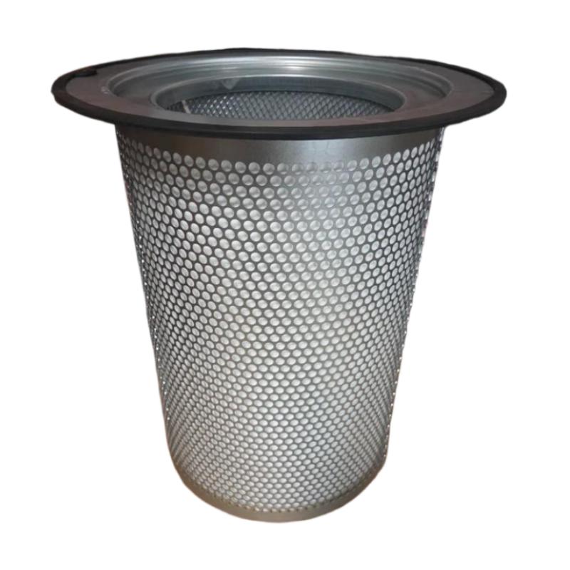
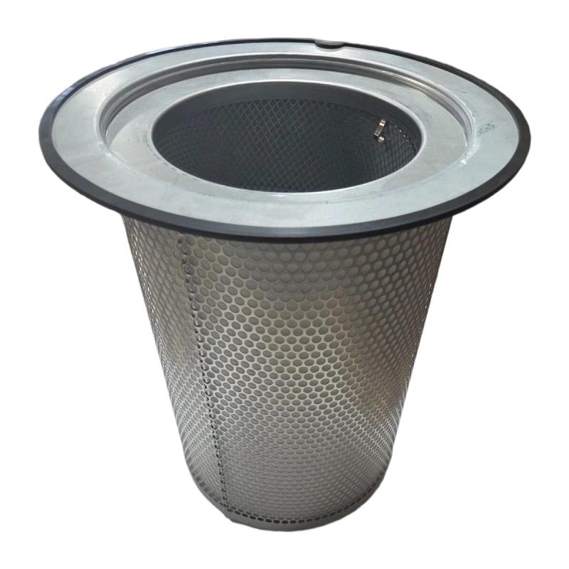
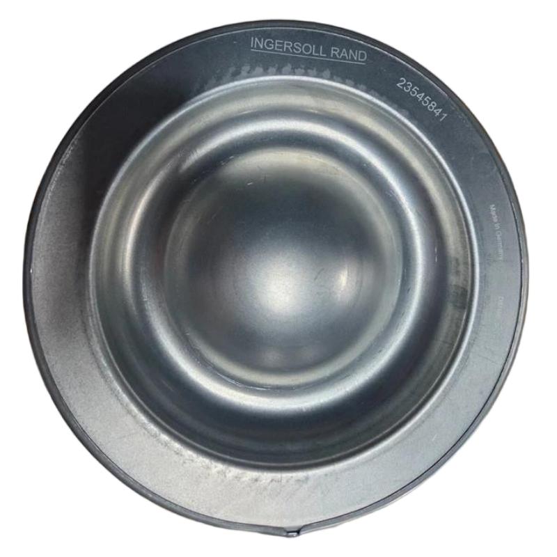
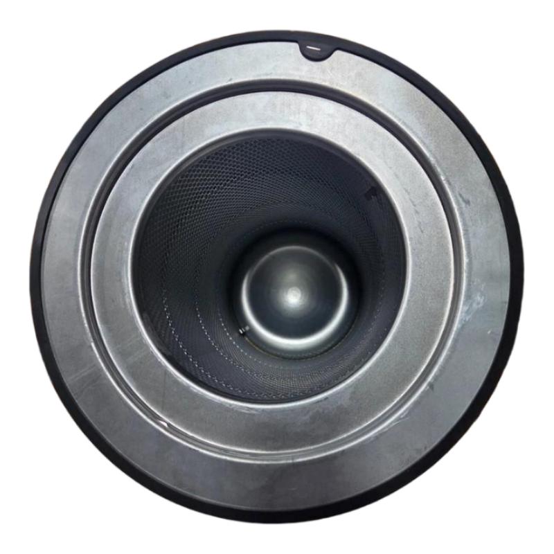
- Ingersoll Rand
- 47555208001 23545841
- Air Oil Separator
- USA
- 375 mm
- 7.5 kg
- Xiamen, China
- New & In Stock
- T/T, PayPal, Western Union
- 1 Year
- 1-3 Working Days
- DHL, UPS, TNT, FedEx and EMS.
- 24-Hour Service
- COO
- 6
Our advantage

Global Logistics
We have a 10-year logistics and express cooperation agreement, so our products can be shipped to any place in the world.

Brand new and original
Our products are imported in bulk from the place of origin. Because of the cooperative relationship, our products are all original and 100% new.

24-hour service
We provide 7*24 hours service to our customers. We will be there whenever you need us.

Price advantage
All our products are priced very favorably because we have our own warehouse and supply.
| Company Information | |||
| [email protected] | |||
| Mobile | +8615980777398 | ||
| +8615980777398 | |||
| 15980777398 |
Product Overview
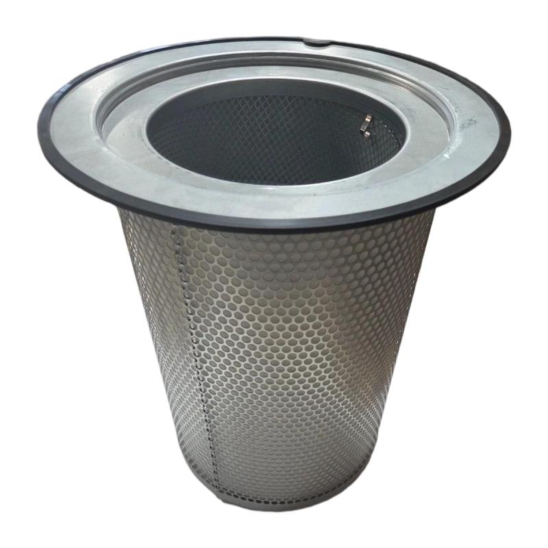
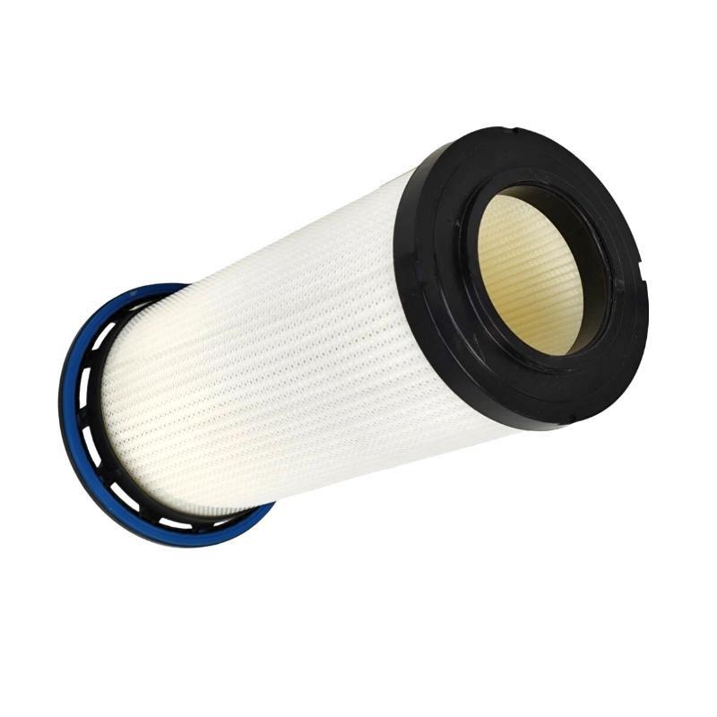
The Ingersoll Rand 47555208001 / 23545841 Air Oil Separator is an industrial compressor filtration component designed for use in compatible compressed-air systems. Air oil separators play an important role in oil-injected rotary screw compressors by separating entrained lubricant from compressed air before the air proceeds through the downstream system. Effective separation helps reduce oil carryover, maintain compressed-air quality, and support reliable compressor operation.
During compression, lubricating oil is commonly introduced into the compression chamber to assist with sealing, cooling, and lubrication. The resulting air-oil mixture must pass through a separation stage before compressed air can be delivered to the outlet. The separator removes most of the entrained oil droplets, allowing recovered lubricant to be returned to the compressor’s oil circuit where the system design permits.
The Ingersoll Rand 47555208001 / 23545841 is identified by the supplied product description as an air oil separator. Its stated diameter is 375 mm, and its stated weight is 7.5 kg. These physical details are useful when planning replacement work, checking available installation space, and managing maintenance inventory.
For compressor maintenance teams, selecting the correct separator is essential. An element that looks similar may have different sealing arrangements, separation characteristics, pressure ratings, or installation dimensions. Before ordering or installing this part, verify the full part number and the intended compressor model against the equipment’s parts documentation.
Technical Specifications
| Parameter | Specification |
|---|---|
| Manufacturer | Ingersoll Rand |
| Part Number | 47555208001 |
| Additional Part Number | 23545841 |
| Product Type | Air Oil Separator |
| Equipment Category | Industrial Air Compressor |
| Primary Function | Separation of entrained oil from compressed air |
| Stated Diameter | 375 mm |
| Weight | 7.5 kg |
| Application | Compatible oil-injected compressor systems |
| Installation Location | Compressor air-oil separation assembly; verify the specific configuration |
| Replacement Requirement | Confirm compressor model, part number, dimensions, and sealing arrangement |
The specifications above reflect the supplied product identification and physical information. The exact compressor models supported, operating pressure limits, filtration efficiency, connection configuration, and service interval should be confirmed from the applicable Ingersoll Rand parts information.
What Is an Air Oil Separator?
An air oil separator is a filtration component used in many oil-injected industrial air compressors. During normal compressor operation, the compression process produces a mixture of compressed air and lubricating oil. Before the air can be sent to the compressed-air distribution system, the oil must be separated from the air stream.
The separator typically uses a specialized separation medium that encourages entrained oil droplets to collect and combine. As the droplets become larger, they can drain toward a collection area and be recovered by the compressor’s oil-return arrangement, depending on the design.
The separation process serves two important purposes. First, it reduces the amount of lubricant carried out with the compressed air. Second, it helps retain compressor oil within the lubrication circuit, supporting appropriate oil levels and stable operating conditions.
The air oil separator is only one part of the compressor’s overall filtration and oil-management system. Its performance also depends on the condition of the lubricant, upstream air-oil mixture, oil-return components, seals, and other compressor assemblies.
Function and Working Principle
1. Receiving the Air-Oil Mixture
In an oil-injected screw compressor, the compression chamber produces compressed air mixed with lubricant. This mixture enters the separator assembly as part of the compressor’s internal flow path.
The exact route and separator arrangement vary by compressor model. The replacement element must match the intended housing and system design.
2. Primary Oil Separation
The compressor’s separation vessel or internal arrangement may remove larger oil droplets through changes in flow direction, reduced velocity, or other separation mechanisms before the mixture reaches the separator element.
The effectiveness of this stage depends on the compressor design and operating conditions. It should not be assumed that every compressor uses an identical separation arrangement.
3. Fine Oil Separation
The separator element provides a medium through which the compressed air passes while fine oil droplets are captured and combined. The resulting oil collects within the separation structure and drains toward the designated oil-return area.
A properly matched separator is designed to balance oil-removal performance with acceptable airflow resistance. An unsuitable element can result in excessive pressure drop, increased oil carryover, or improper sealing.
4. Oil Recovery
Separated lubricant may be returned to the compressor’s oil circuit through a dedicated oil-return line or another design-specific arrangement. This helps reduce lubricant loss during normal operation.
If the oil-return path becomes blocked or damaged, oil may accumulate in the separator assembly and cause symptoms similar to a worn separator. Troubleshooting should therefore include the surrounding oil-return components.
5. Delivery of Separated Compressed Air
After passing through the separation stage, the compressed air proceeds toward the compressor outlet and any downstream treatment equipment. The separator reduces oil carryover but should not be treated as a substitute for downstream filtration where a specific compressed-air purity level is required.
Role in Industrial Compressed-Air Systems
The Ingersoll Rand 47555208001 / 23545841 air oil separator is intended to perform a critical maintenance function within a compatible compressor system. Its condition can affect lubricant consumption, compressor operating efficiency, downstream air quality, and maintenance frequency.
A typical compressed-air system may include the following functional stages:
Air Intake → Compression with Lubricant Injection → Air-Oil Separation → Aftercooling → Moisture Separation → Air Treatment and Distribution
The actual sequence depends on the compressor model and installed equipment.
A separator in good condition helps reduce the transfer of compressor lubricant into downstream piping and equipment. This can be important in manufacturing operations where excess oil may contaminate pneumatic equipment, affect production processes, or increase the load on downstream filtration systems.
The separator also contributes to oil management within the compressor. When the element becomes restricted, damaged, or improperly sealed, the compressor may experience increased differential pressure, higher oil carryover, or other abnormal operating conditions.
Industrial Applications
Manufacturing Facilities
Manufacturing plants rely on compressed air for pneumatic tools, actuators, fixtures, and automated production equipment. An effective separator helps reduce lubricant carryover from oil-injected compressors, supporting the performance of downstream equipment.
Packaging and Assembly Lines
Packaging and assembly operations often use compressed air for clamping, movement, cleaning, and product handling. Separator maintenance helps control compressor oil carryover, although additional air treatment may be necessary where the process has strict air-quality requirements.
Material Handling Systems
Pneumatic conveying controls, lifting equipment, and other material-handling systems may depend on a stable compressed-air supply. Proper compressor maintenance, including separator replacement when required, helps support dependable operation.
Industrial Workshops
Workshops use compressed air for pneumatic tools, maintenance equipment, and general plant services. A correctly matched separator helps limit lubricant entering the air distribution system.
Process Industries
Chemical, pharmaceutical, food, and other process facilities may use compressed air for a range of equipment functions. The required air purity depends on the application, and a separator alone does not guarantee oil-free or process-grade compressed air.
Continuous-Duty Compressor Installations
Facilities operating compressors for extended periods need a planned maintenance program covering separator elements, filters, lubricant, cooling systems, and other service components. Replacing the separator at the appropriate interval helps reduce the risk of unexpected compressor interruption.
Signs of a Worn or Restricted Air Oil Separator
Separator condition should be assessed using the compressor manufacturer’s service criteria and operating data. Several symptoms may indicate that inspection or replacement is required.
Increased Differential Pressure
As the separator element accumulates contaminants or becomes restricted, the pressure difference across it may increase. Excessive differential pressure can reduce system efficiency and may trigger a compressor alarm if the equipment monitors this condition.
A pressure-drop problem should be evaluated alongside other possible causes, including unsuitable lubricant, incorrect operating conditions, or problems elsewhere in the airflow path.
Excessive Oil Carryover
An increase in oil downstream of the compressor may indicate separator deterioration, incorrect installation, damaged seals, or a problem with the oil-return system.
Before replacing the element, check the compressor’s oil level, operating conditions, and oil-return arrangement according to the service procedure.
Unusual Lubricant Consumption
If the compressor requires more lubricant than normal, oil carryover may be one possible cause. However, external leaks, internal leakage, incorrect oil level, and other system faults can produce similar symptoms.
Track lubricant consumption over time and investigate changes rather than assuming the separator is always responsible.
Abnormal Compressor Operating Conditions
A restricted separator or related airflow problem may contribute to abnormal pressure behavior, increased energy use, or maintenance alarms. Use the compressor’s monitoring information and service documentation to determine whether the separator is the likely cause.
Visible Damage or Seal Problems
During scheduled service, inspect the removed element and associated sealing surfaces for deformation, damage, contamination, or signs of improper installation. Do not reinstall an element that fails the applicable service requirements.
Installation and Replacement Guide
Air oil separator replacement should be carried out by qualified personnel using the procedure specified for the compressor model. The separator assembly may contain hot lubricant and pressurized air, creating significant hazards if the equipment is opened incorrectly.
1. Confirm the Replacement Part
Before beginning work, verify the part number 47555208001 and the associated number 23545841 against the compressor’s approved parts information.
Confirm the separator’s dimensions, housing arrangement, sealing surfaces, and other model-specific requirements. The stated diameter of 375 mm is a useful identification detail but does not by itself establish compatibility.
2. Shut Down and Isolate the Compressor
Stop the compressor according to the manufacturer’s shutdown procedure. Isolate the electrical supply and apply the site’s lockout/tagout procedure.
Allow hot components to cool, then verify that the relevant system sections have been fully depressurized. Never loosen a separator housing or pressure-containing connection while it may still contain trapped pressure.
3. Access the Separator Assembly
Remove the required covers and access components according to the equipment service procedure. Record the arrangement of hoses, pipes, fittings, and associated parts before disassembly.
Avoid introducing dust, fibers, or other contaminants into the open compressor system.
4. Remove the Used Element
Remove the separator using the specified method. Inspect the housing, cover, sealing surfaces, and oil-return components for contamination or damage.
Dispose of the used separator and any contaminated materials in accordance with site environmental and waste-management requirements.
5. Inspect the Housing and Seals
Clean the relevant contact surfaces using approved methods. Check the sealing arrangement and replace seals when required by the service instructions.
Do not use cleaning methods or materials that could damage the housing, sealing surfaces, or other compressor components.
6. Install the Replacement Separator
Confirm the replacement part number and orientation before fitting the new element. Install it according to the compressor manufacturer’s instructions.
Ensure that the separator seats correctly and that all seals are positioned as specified. Improper seating or damaged seals may allow oil carryover or leakage.
7. Reassemble the Compressor
Reconnect the removed components and tighten fasteners to the specified torque values. Restore hoses, pipes, covers, and fittings to their correct positions.
Do not estimate torque values or alter the oil-return configuration without the appropriate service information.
8. Conduct Post-Maintenance Checks
Before returning the compressor to normal service, verify that tools and loose materials have been removed from the work area and that all required covers are installed.
Restore power and operate the compressor in accordance with the manufacturer’s commissioning procedure. Monitor operating pressure, separator differential pressure where available, lubricant leakage, alarms, and other relevant indicators.
If abnormal oil carryover or pressure behavior persists, investigate the complete separation system rather than assuming that the new element is defective.
Troubleshooting the Ingersoll Rand Air Oil Separator
Excessive Oil in the Compressed Air
Possible causes include a worn or incorrectly installed separator, damaged seals, a blocked oil-return line, unsuitable lubricant, excessive oil level, or abnormal compressor operating conditions.
Check the separator’s part number and installation, inspect the oil-return path, and verify lubricant level and type according to the compressor service instructions.
High Separator Differential Pressure
A high differential-pressure reading may indicate a restricted element, contamination, unsuitable operating conditions, or an issue with the pressure-measurement arrangement.
Compare the reading with the compressor manufacturer’s limits. If replacement is required, use the specified separator and investigate any unusual contamination that may have shortened the previous element’s service life.
Oil Consumption Remains High After Replacement
If oil consumption remains excessive after a new separator is installed, inspect the installation and sealing surfaces. Check the oil-return system and look for other sources of lubricant loss.
Confirm that the replacement is correct for the compressor and that the system is operating within its intended conditions.
Leakage Around the Separator Housing
Leakage may be caused by damaged seals, incorrect seating, contaminated contact surfaces, loose fasteners, or damaged housing components.
Shut down and depressurize the system before inspecting the assembly. Replace damaged sealing components and follow the specified assembly procedure.
Separator Service Life Is Shorter Than Expected
Premature restriction or deterioration may be associated with contamination, lubricant condition, excessive operating temperature, abnormal compressor duty, or problems elsewhere in the system.
Review maintenance records and operating data to identify recurring patterns. Repeatedly replacing the separator without correcting the underlying cause may lead to unnecessary costs and further downtime.
Maintenance Recommendations
A consistent maintenance program helps protect compressor reliability and control lubricant carryover.
- Follow the specified service interval: Use the compressor manufacturer’s maintenance schedule and adjust service planning only where permitted by the applicable instructions.
- Monitor differential pressure: Where the compressor provides this measurement, record changes and compare them with the recommended service limits.
- Track lubricant consumption: Unexpected changes may indicate separator problems or another compressor-system fault.
- Inspect associated components: Check the oil-return line, seals, housing, and related filtration components during scheduled maintenance.
- Use the correct lubricant: Confirm lubricant type and condition according to the compressor model requirements.
- Maintain clean working conditions: Prevent dust and debris from entering the compressor during service.
- Record replacement details: Document the installed part number, date, operating hours, and any abnormal observations.
A separator should not be replaced solely on appearance or an arbitrary schedule when the compressor manufacturer specifies a different maintenance method. Use the approved service criteria for the equipment.
Compatible System Components
An air oil separator operates as part of a larger compressor assembly. The following components may be relevant during inspection or maintenance, depending on the compressor design.
| Component | Function |
|---|---|
| Compressor Air-Oil Separation Housing | Contains the separator assembly |
| Air Oil Separator Element | Removes entrained lubricant from compressed air |
| Separator Seals and Gaskets | Help maintain sealing at the specified interfaces |
| Oil-Return Line | Returns separated lubricant where the system design requires it |
| Compressor Lubricant | Supports sealing, cooling, and lubrication in oil-injected compressors |
| Air Intake Filter | Reduces intake contamination |
| Oil Filter | Removes contaminants from the lubricant circuit |
| Aftercooler | Reduces compressed-air temperature |
| Moisture Separator | Removes condensed liquid from the air stream |
| Downstream Air Filter | Provides additional filtration according to application requirements |
These are functional component categories, not a guarantee of compatibility with every Ingersoll Rand compressor. Confirm individual part numbers against the specific compressor model before ordering related components.
Replacement and Procurement Considerations
When purchasing the Ingersoll Rand 47555208001 / 23545841 air oil separator, accurate identification is essential to avoid installation problems and unnecessary downtime.
Before ordering, confirm the following details:
- Full part number and any associated number
- Compressor model and serial number
- Separator diameter and overall dimensions
- Housing and sealing configuration
- Required operating-pressure suitability
- Applicable service and replacement instructions
- Supplier documentation and product condition
The stated 375 mm diameter and 7.5 kg weight can help with preliminary physical identification, handling, and logistics planning. However, these measurements should be checked against the actual component and must not replace confirmation of the compressor-specific part number.
For critical compressor installations, it is also useful to retain maintenance records showing when the separator was replaced, the operating hours at replacement, and any observed differential-pressure or oil-carryover issues. This information helps maintenance teams plan future service and identify recurring faults.
Key Advantages of Correct Separator Maintenance
Reduced Oil Carryover
A correctly selected and properly installed separator helps limit the transfer of lubricant into the compressed-air outlet.
Support for Compressor Efficiency
Maintaining the separator in accordance with the manufacturer’s requirements helps avoid excessive restriction caused by a deteriorated or contaminated element.
Improved Equipment Reliability
Monitoring separator condition and related components can help identify problems before they cause extended compressor downtime.
Protection of Downstream Equipment
Reducing lubricant carryover helps control oil contamination in downstream piping and equipment. Additional treatment may still be necessary for applications with strict compressed-air purity requirements.
More Predictable Maintenance Planning
Recording operating hours, differential pressure, lubricant consumption, and replacement dates can improve maintenance scheduling and spare-parts management.
Technical FAQs
What is the Ingersoll Rand 47555208001 / 23545841?
It is identified by the supplied product description as an air oil separator for a compatible Ingersoll Rand compressor system.
What is the stated diameter of this separator?
The stated diameter is 375 mm. Confirm the actual dimensions and housing requirements before ordering a replacement.
How much does the separator weigh?
The supplied weight is 7.5 kg.
What does an air oil separator do?
It separates entrained lubricant from compressed air in compatible oil-injected compressor systems. The separated oil may be returned to the lubricant circuit, depending on the compressor design.
What are common signs that a separator needs attention?
Potential signs include increased differential pressure, excessive oil carryover, unusual lubricant consumption, leakage, or relevant compressor alarms. These symptoms can also have other causes and should be investigated systematically.
Can any 375 mm separator replace this part?
No. Diameter alone does not establish compatibility. The complete part number, housing configuration, sealing arrangement, operating requirements, and compressor model must be checked.
Does replacing the separator guarantee oil-free compressed air?
No. An air oil separator reduces oil carryover in the compressor’s output, but it does not necessarily provide oil-free or process-grade compressed air. Additional filtration and air-treatment equipment may be required.
What should be checked if oil carryover continues after replacement?
Verify the replacement part, installation, sealing surfaces, oil-return path, lubricant level and type, and compressor operating conditions. Consult the applicable service procedure if the problem persists.
Conclusion
The Ingersoll Rand 47555208001 / 23545841 Air Oil Separator is identified as a compressor separation component designed to reduce lubricant carryover from compressed air in a compatible oil-injected compressor system. Correct separator selection and maintenance help support compressed-air quality, lubricant management, and dependable compressor operation.
With a stated diameter of 375 mm and a weight of 7.5 kg, the component’s physical specifications are useful for maintenance planning and replacement logistics. Reliable performance nevertheless depends on matching the separator to the exact compressor model, maintaining the associated seals and oil-return components, and following the approved installation procedure.
Before replacement, confirm the full part number and compressor compatibility. Proper isolation, complete depressurization, careful installation, and post-maintenance checks are essential for safe servicing and reliable long-term operation.