

ProductPRODUCT
Featured products


Contact Us
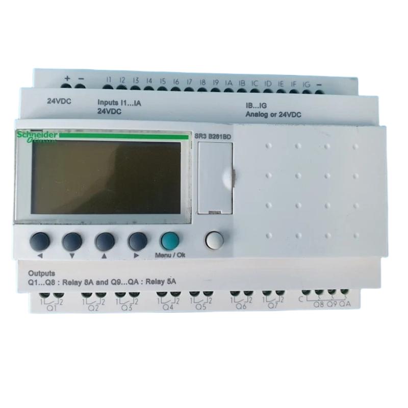
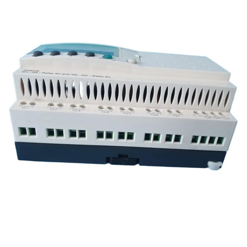
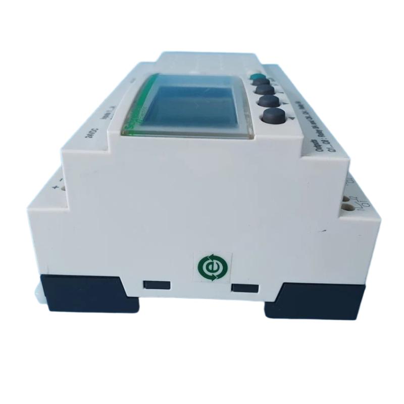
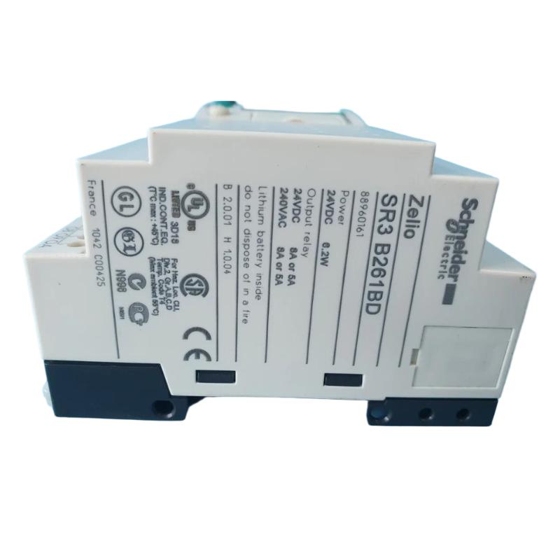
- Schneider
- SR3B261BD
- Modular Smart Relay
- France
- 124.6 x 107.6 x 59.5 mm
- 0.4 kg
- Xiamen, China
- New & In Stock
- T/T, PayPal, Western Union
- 1 Year
- 1-3 Working Days
- DHL, UPS, TNT, FedEx and EMS.
- 24-Hour Service
- COO
- 6
Our advantage

Global Logistics
We have a 10-year logistics and express cooperation agreement, so our products can be shipped to any place in the world.

Brand new and original
Our products are imported in bulk from the place of origin. Because of the cooperative relationship, our products are all original and 100% new.

24-hour service
We provide 7*24 hours service to our customers. We will be there whenever you need us.

Price advantage
All our products are priced very favorably because we have our own warehouse and supply.
| Company Information | |||
| [email protected] | |||
| Mobile | +8615980777398 | ||
| +8615980777398 | |||
| 15980777398 |
Product Overview
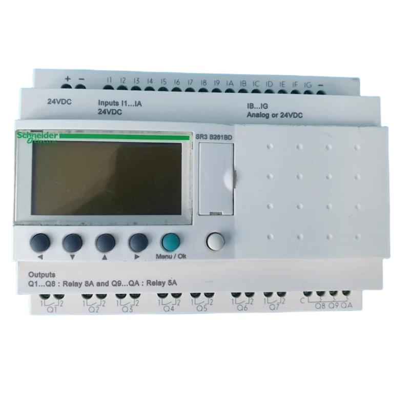
The Schneider Electric SR3B261BD Modular Smart Relay is a programmable control device designed for compact automation systems, machine-control applications, and electrical control panels. Belonging to the Schneider Electric Zelio Logic smart relay product family, it provides a practical way to implement basic control logic without requiring a larger programmable logic controller (PLC) for every application.
Smart relays combine programmable logic with input and output interfaces to coordinate electrical equipment according to predefined operating conditions. Depending on the installed configuration and application program, they can support functions such as switching, timing, counting, sequential operation, and equipment interlocking. These capabilities help simplify control circuits that would otherwise rely on multiple conventional relays and separate timing devices.
The SR3B261BD is identified as a modular smart relay. Its role in an automation system is to process connected input signals, execute the configured program, and update output states to control compatible external equipment. It can be considered for small machines, auxiliary control systems, building services, and other applications where the required control logic is relatively straightforward.
With listed dimensions of 124.6 × 107.6 × 59.5 mm and a weight of approximately 0.4 kg, the SR3B261BD is suitable for consideration in compact electrical enclosures where efficient use of panel space and clear control-system organization are important.
For installation and replacement, the complete model designation should be checked against the device label. Electrical supply requirements, input and output characteristics, programming compatibility, and supported accessories must be verified for the exact hardware version before the relay is integrated into an operating system.
Technical Specifications
| Parameter | Specification |
|---|---|
| Manufacturer | Schneider Electric |
| Model | SR3B261BD |
| Product Type | Modular Smart Relay |
| Product Family | Zelio Logic smart relay family |
| Main Function | Programmable logic control |
| Control Applications | Switching, timing, counting, sequencing, and interlocking |
| Operating Principle | Programmed processing of input conditions and control of outputs |
| Installation | Electrical control panel; confirm mounting requirements for the exact version |
| Programming | Verify the supported programming method and software compatibility |
| Expansion Support | Confirm supported expansion options for the installed model |
| Dimensions | 124.6 × 107.6 × 59.5 mm |
| Weight | 0.4 kg |
| Typical Applications | Small machines, auxiliary control, building services, and industrial automation |
| Supply Requirements | Verify from the product label and applicable technical documentation |
| Input and Output Details | Confirm the exact hardware configuration before wiring |
What Is the Schneider SR3B261BD Smart Relay?
The SR3B261BD is a modular smart relay designed to provide programmable control for applications that do not necessarily require a full PLC system. It can replace suitable portions of traditional relay logic by allowing control conditions to be defined in a program rather than implemented entirely through hardwired components.
In conventional electrical control systems, a machine sequence may require multiple auxiliary relays, timer relays, counters, and interconnections. As the number of conditions increases, the wiring can become difficult to modify and troubleshoot. A programmable smart relay can consolidate appropriate logic functions within one device, helping reduce wiring complexity and improve maintainability.
The smart relay receives signals from connected field devices and evaluates them according to its programmed logic. Based on the result, it changes its outputs to initiate or stop specific operations. The actual control functions available in a particular installation depend on the hardware configuration, program, external devices, and application requirements.
The SR3B261BD should be selected only after confirming that its electrical characteristics and functional capabilities meet the needs of the intended control system.
Function and Working Principle
1. Input Signal Monitoring
The smart relay receives signals from compatible field devices. Depending on the verified installation, these may include push buttons, selector switches, limit switches, equipment status contacts, or other suitable input devices.
These signals represent the operating conditions of the machine or process. Correct wiring and electrical compatibility are essential to ensure that the controller detects input changes reliably.
2. Programmed Logic Processing
The relay evaluates its input states according to the configured program. The program defines which conditions must be satisfied before a particular output is activated.
For example, an output may be enabled only when a start command is present and a required interlock is satisfied. A timer can introduce a delay, while a counter can track repeated events if the required function is supported by the installed version.
3. Output Switching
After processing the input conditions, the smart relay updates its output states. The outputs can be used to control compatible external devices, such as interface relays, contactors, indicator lamps, or other electrical loads within the permitted ratings.
Before connecting a load directly, verify the output type and rated switching capacity. Motors, solenoids, and other inductive loads may require appropriately rated external switching devices and protective components.
4. Timing and Counting Functions
Timing and counting functions are useful when equipment must operate according to a defined interval or number of events.
Examples include delayed startup, timed ventilation, cycle counting, and basic process sequencing. The exact functions, limits, and configuration methods should be checked against the applicable documentation for the SR3B261BD.
5. Automatic Sequence Execution
Once the program has been configured and the system commissioned, the smart relay can perform the specified sequence automatically. It continues to evaluate the input conditions and update outputs while the system is operating.
A simplified control sequence is:
Field Signals → Input Processing → Program Execution → Output Switching → Equipment Operation
The reliability of this sequence depends on correct programming, suitable field devices, proper electrical installation, and adequate protection of the controlled equipment.
Role in Industrial Control Systems
Within an industrial control panel, the SR3B261BD can serve as a local controller for small machines and auxiliary systems. It is particularly useful when a limited set of control functions must be automated without introducing the cost or complexity of a larger PLC platform.
Its potential roles include:
- Executing programmed start and stop sequences.
- Coordinating multiple operating conditions.
- Implementing basic timing and counting logic.
- Managing suitable equipment interlocks.
- Controlling compatible output circuits.
- Replacing appropriate portions of conventional relay logic.
- Reducing the amount of hardwired control circuitry.
- Supporting repeatable machine operation.
For example, a small machine may require an operator start command, a position switch, and a timed operating step. A smart relay can evaluate these signals and issue the appropriate output commands according to the configured sequence.
However, the smart relay should not automatically be treated as a safety-rated controller. Emergency stops, protective guarding, and other personnel-safety functions must be implemented using suitable safety devices and architectures that meet the requirements of the application.
Industrial Applications
Small Machine Control
The SR3B261BD can be evaluated for machines that require simple operating sequences, timed actions, counting, and interlocking. Programmable logic can reduce the need for numerous separate control relays.
Pump and Water-System Automation
Basic pump-control systems may use level switches, pressure switches, or other compatible signals to determine when equipment should operate. A smart relay can coordinate control commands when its configuration matches the required application.
Motor protection, dry-running protection, overload protection, and other necessary safeguards must be provided separately where required by the system design.
Ventilation and Building Services
Small ventilation systems and auxiliary building equipment may use scheduled switching, delayed operation, and simple interlocks. A smart relay can provide local control for these functions when the device’s capabilities and electrical ratings are appropriate.
Lighting Control
Basic lighting applications may require timed switching, manual control, or predefined operating sequences. The smart relay can be considered for such arrangements, provided that the connected loads and switching devices are compatible with its output specifications.
Conveyor and Material Handling Systems
Simple conveyor applications may require start/stop logic, cycle counting, sequence coordination, or interlocking between adjacent equipment. The SR3B261BD may be suitable when the number of required signals and the response requirements fall within its capabilities.
Packaging and Assembly Equipment
Small packaging machines and assembly stations can use programmable relay logic for repetitive operations, timed steps, and auxiliary machine functions. More complex systems involving high-speed processing, extensive I/O, advanced networking, or coordinated motion may require a more capable controller.
Electrical Control Panels
The device can help consolidate suitable control functions within a compact panel. Proper circuit protection, terminal organization, labeling, and wiring separation remain important for safe operation and maintainability.
Installation and System Integration
Correct installation is necessary to achieve reliable operation and avoid faults caused by incorrect wiring, unsuitable power, or environmental conditions.
Confirm the Model Number
Before installation, verify the complete part number SR3B261BD on the product label. Check the supply requirements, terminal assignments, input and output characteristics, mounting requirements, and supported programming tools for the exact version.
Do not rely on the appearance of the relay or the specifications of a similar model to determine its electrical connections.
Prepare the Control Enclosure
Select a mounting location that provides suitable environmental protection, adequate ventilation, and access to wiring terminals. The enclosure should protect the device from excessive heat, moisture, dust, vibration, and contamination.
Follow the specified mounting clearances and installation instructions for the unit.
Verify the Power Supply
Confirm the rated supply and connection method from the product label and applicable technical documentation. Incorrect power connections can damage the relay or create unsafe operating conditions.
Isolate the relevant electrical circuits before installation or maintenance and follow the site’s lockout and electrical safety procedures.
Connect Input Devices
Identify each field signal and connect it to the appropriate terminal according to the verified wiring diagram. Check that the signal type and electrical level are compatible with the relay input.
Use suitable conductors, secure terminal connections, and clear wire labels. Keep control wiring properly routed and separated from power conductors where required by the installation design.
Connect Output Circuits
Verify the output type and electrical ratings before connecting the controlled equipment. Where the load exceeds the relay’s direct switching capability, use an appropriately rated contactor or interface relay.
Provide suitable circuit protection and any required suppression components based on the characteristics of the connected load.
Configure the Program
Create or load the control program using a programming method confirmed to be compatible with the installed hardware. Define input conditions, output assignments, timers, counters, reset behavior, and interlocks as required by the application.
Maintain a backup of the approved program and document any changes made during commissioning.
Commission the System
Before normal operation, verify the wiring and test each input and output individually. Confirm that the program behaves as intended during startup, normal operation, stopping, resetting, and relevant fault conditions.
Test protective functions and equipment interlocks according to the applicable procedures. Do not place the machine into service until the complete control system has been checked.
Programming and Configuration Guidelines
Define the Operating Sequence
Prepare a written description of the intended machine behavior before programming. Identify the conditions required for startup, the actions that occur during operation, and the conditions that cause the system to stop or reset.
A clear sequence description helps prevent contradictory logic and simplifies troubleshooting.
Use Consistent Signal Names
Where supported by the programming environment, use meaningful names for input signals, outputs, timers, counters, and internal logic elements. Consistent naming makes the program easier to understand and maintain.
Apply Appropriate Interlocking
Interlocks help prevent incompatible commands or unintended transitions between operating steps. For example, a program may require confirmation that one operation has completed before another can begin.
Software interlocking is not a substitute for required safety-rated hardware.
Check Power-Loss Behavior
Determine how the application should respond when the power supply is interrupted and restored. Test startup conditions, retained states, reset requirements, and output behavior to prevent unexpected equipment movement or operation.
Maintain Program Records
Keep the approved program, I/O list, wiring diagrams, and commissioning notes together. Record revisions and ensure that maintenance staff can identify the version currently installed in the equipment.
Troubleshooting the Schneider SR3B261BD
Troubleshooting should begin with the complete control circuit rather than assuming that the smart relay itself is defective.
The Relay Does Not Start
Possible causes include an incorrect supply, loose power connections, an open protective device, or an internal hardware fault.
Recommended checks:
- Verify the supply against the product label.
- Inspect the power wiring and terminal connections.
- Check the associated circuit protection.
- Confirm that the supply remains stable during operation.
- Look for visible signs of overheating or physical damage.
Always isolate the equipment before touching exposed electrical connections.
Input Signals Are Not Detected
If a field device changes state but the control program does not respond, inspect the field device, signal wiring, terminal assignment, and input compatibility.
Where supported, use the appropriate diagnostic or programming interface to observe the input state. Confirm that the signal reaches the correct terminal before considering replacement of the relay.
Outputs Do Not Operate
An output may remain inactive because the programmed conditions have not been satisfied, the output assignment is incorrect, or the external load circuit is faulty.
Check the program logic, output status, connected interface relay or contactor, load supply, and associated protection devices. If the relay indicates an active output but the equipment does not operate, investigate the external switching circuit.
Unexpected Timing or Sequence
Incorrect timer settings, unsuitable logic conditions, unintended latching, or incomplete reset logic can cause sequence problems.
Review the program and compare the actual behavior with the documented sequence. Test individual conditions and timing stages before operating the complete machine cycle.
Intermittent Operation
Intermittent faults can result from loose terminals, damaged wiring, unstable supply voltage, electrical interference, vibration, or a faulty field device.
Inspect the installation and reproduce the problem under controlled conditions. Observe relevant input and output states, where possible, to determine whether the problem originates in the control program, field wiring, external equipment, or relay.
Programming or Connection Problems
If a programming tool cannot communicate with the device or transfer the intended program, confirm that the software version, interface, cable, and connection procedure are supported by the exact hardware.
Check the physical connection and follow the applicable programming instructions. Do not assume that accessories compatible with another smart relay are also suitable for the SR3B261BD.
Maintenance Recommendations
Regular maintenance helps preserve the reliability of the SR3B261BD and the surrounding control system.
Inspect electrical connections. Check for loose terminals, damaged insulation, corrosion, or signs of excessive heating during scheduled maintenance.
Maintain a clean enclosure. Keep the control cabinet free from excessive dust and contamination. Use cleaning methods suitable for electrical equipment and prevent moisture from entering the device.
Check operating conditions. Verify that the enclosure temperature, ventilation, and environmental conditions remain within the permitted limits.
Back up the program. Keep an approved copy of the control program and record changes with clear revision information.
Inspect connected devices. Check switches, sensors, contactors, interface relays, and other external equipment. Faulty field devices can produce symptoms that resemble controller failure.
Test operating and interlock logic. Verify normal start/stop behavior, reset conditions, and required protective functions according to the site’s maintenance plan.
Investigate abnormal behavior. Unexpected switching, repeated resets, or inconsistent sequences should be diagnosed promptly to prevent production interruptions.
Compatible System Components
The SR3B261BD may form part of a control system containing several categories of electrical and automation equipment. Actual compatibility depends on the relay’s electrical configuration and the requirements of the application.
| Component Category | Function |
|---|---|
| Push Buttons and Selector Switches | Provide manual operating commands |
| Limit Switches | Detect equipment position or travel limits |
| Compatible Sensors | Provide process or machine-status signals |
| Interface Relays | Adapt or isolate control circuits where required |
| Contactors | Switch suitable power loads |
| Circuit Protection Devices | Protect electrical circuits and wiring |
| Control Power Supply | Provides the required operating power |
| Terminal Blocks | Organize field wiring |
| Indicator Lamps | Display operating states and alarms |
| Programming Interface | Supports configuration when compatible |
| Electrical Enclosure | Provides mounting and environmental protection |
Before adding expansion modules or programming accessories, verify that the specific component is supported by the SR3B261BD hardware version. Similar product-family names do not guarantee mechanical or electrical interchangeability.
Replacement and Procurement Considerations
When purchasing or replacing the Schneider Electric SR3B261BD, verify the complete model designation and the configuration of the existing installation.
Key checks include:
- Full model number and hardware identification.
- Supply voltage and terminal configuration.
- Input and output types and ratings.
- Mounting space and physical dimensions.
- Programming and software compatibility.
- Supported accessories or expansion options.
- Existing wiring condition.
- Availability of the original control program.
The listed dimensions are 124.6 × 107.6 × 59.5 mm, and the listed weight is 0.4 kg. These values support panel-layout planning and inventory management, but physical dimensions alone cannot establish electrical compatibility.
If an alternative model is being considered, compare its electrical requirements, I/O configuration, programming behavior, and supported accessories before installation. A similar-looking smart relay may have different terminal assignments or operating characteristics.
Key Advantages
Programmable Control in a Compact Device
A smart relay combines suitable logic functions in one programmable device, reducing the need for multiple conventional control components.
Flexible Operating Sequences
The control program can be adapted to supported application requirements without redesigning every part of a hardwired circuit.
Reduced Wiring Complexity
Consolidating control logic can simplify wiring and make electrical drawings easier to manage.
Support for Timing and Counting
Programmable timing and counting functions can support repetitive processes and basic machine sequences when available on the installed version.
Suitable for Small Automation Applications
A smart relay offers a practical control option for applications that do not require the broader capabilities of a full PLC.
Improved Maintainability
Clear program documentation, labeled wiring, and organized control logic can help technicians identify faults and implement approved changes.
Technical FAQs
What is the Schneider Electric SR3B261BD?
The SR3B261BD is identified as a modular smart relay for programmable control in compact automation systems and electrical control applications.
What are the dimensions of the SR3B261BD?
The listed dimensions are 124.6 × 107.6 × 59.5 mm.
What is the weight of the SR3B261BD?
The listed weight is approximately 0.4 kg.
What functions can a smart relay perform?
Depending on the exact hardware and program, a smart relay can support logic processing, switching, timing, counting, sequencing, and basic interlocking.
Can the SR3B261BD replace conventional relays?
It may replace suitable portions of a conventional relay circuit. External contactors, interface relays, protective devices, or safety components may still be required depending on the application.
Can the SR3B261BD replace a full PLC?
Not in every application. A smart relay is generally intended for more limited control tasks. Systems requiring extensive I/O, advanced communications, high-speed processing, coordinated motion, or specialized safety functions may need a more capable controller.
What should be verified before installation?
Confirm the complete model number, supply requirements, terminal assignments, input and output characteristics, wiring diagram, mounting requirements, and supported programming tools.
What causes a smart relay to malfunction?
Possible causes include supply problems, incorrect wiring, faulty field devices, unsuitable program logic, overloaded outputs, electrical interference, or internal hardware damage.
Is the SR3B261BD suitable for emergency-stop control?
It should not be assumed to provide safety-rated emergency-stop functionality. Safety functions must use appropriate safety devices and system designs validated for the application.
Conclusion
The Schneider Electric SR3B261BD Modular Smart Relay is intended for compact programmable control applications in which basic logic, timing, counting, switching, and sequencing can simplify machine operation. By consolidating suitable control functions into a programmable device, it can reduce hardwired relay complexity and make control logic easier to maintain.
With listed dimensions of 124.6 × 107.6 × 59.5 mm and a weight of 0.4 kg, the SR3B261BD can be considered for space-conscious electrical panels and small automation systems.
Reliable performance depends on correct product identification, suitable electrical connections, a well-documented control program, and thorough commissioning. Before installing or replacing the relay, verify its exact hardware characteristics and ensure that the complete control system meets the operational and safety requirements of the intended application.